 Контактор,автоматический выключатель,датчик,Кодер,ПЛК,Конвертер


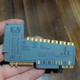
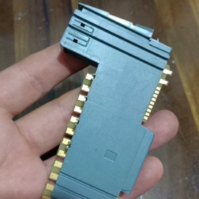
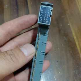
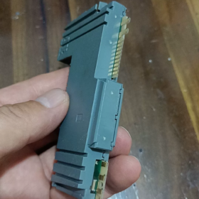
Пояснение кода модели
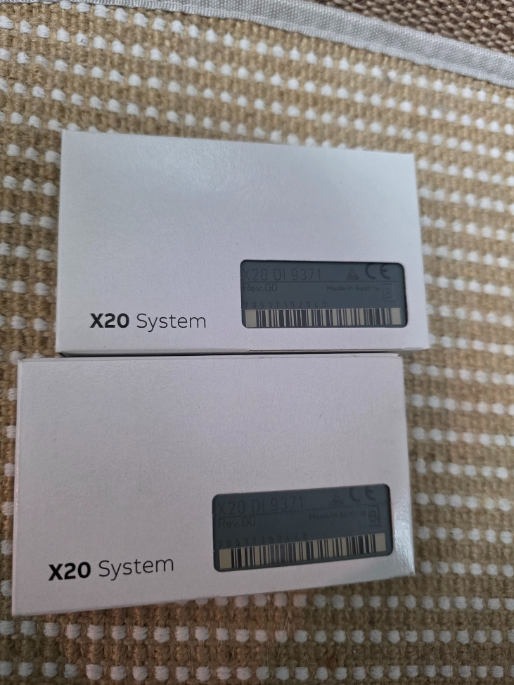
X20DI9371
X20: X20 distributed I/O system platform
ОТ: Цифровой вход
9371: Module specification code
- Main Electrical & Hardware Specifications
| Элемент | Спецификация |
| Number of Channels | 16 цифровые входы |
| Тип входа | 24 VDC sinking / sourcing compatible, МЭК 61131-2 Тип 3 |
| Номинальное входное напряжение | 24 В постоянного тока (operating range: 18~30 VDC) |
| Входное сопротивление | Приблизительно. 3.9 кОм |
| Logic ON (1) Порог | ≥11 VDC |
| Logic OFF (0) Порог | ≤5 VDC |
| Input Current per Channel | ≈6 mA @24 VDC |
| Response Delay | Typical 0.1 РС; configurable hardware filter: 0.1 / 0.5 / 3 / 15 РС (parameter setting via software) |
| Метод изоляции | Group isolation: 4 каналы на группу, общий 4 isolated groups |
| Isolation voltage between groups: 500 ВАК | |
| Шинный интерфейс | X20 Link internal system bus |
| Индикация состояния | Independent LED for each channel; module power LED |
| Потребляемая мощность | Typ. 1.8 Вт |
- Механический & Экологические характеристики
Монтаж: Стандартный 35 мм DIN-рейка, горизонтальная установка
Размеры: Вт 40 мм × В 100 мм × Г 76.5 мм
Рабочая температура: -20 ℃ ~ +60 ℃ (inside control cabinet)
Хранилище / Температура транспортировки: -40 ℃ ~ +85 ℃
Класс защиты: IP20 (только для установки в шкаф)
Сертификаты: CE, UL 508, GL marine certification, соответствует EN 61000 EMC industrial standards
- Внутренняя структура & Определение терминала
16 каналы разделены на 4 isolated groups:
Group1: CH0~CH3
Group2: CH4~CH7
Group3: CH8~CH11
Group4: CH12~CH15
⚠️ Important Wiring Rule: The common terminal of one isolated group must share the same 24 V polarity; Do NOT connect separate, non-referenced 24 V power supplies to different isolated groups, otherwise potential difference may damage the isolation circuit.
Wiring Configurations
- Sourcing Input (ПНП Датчик)
Sensor output connects to module DI terminal; module common terminals connect to 0V(Земля)
- Sinking Input (NPN Sensor)
Sensor power terminal connects to 24V+, sensor output to DI terminal; module common terminals connect to +24V
- Принцип работы
External digital sensor signal → Front-end RC hardware filter circuit → Optocoupler isolation group → Signal shaping circuit → X20 bus communication chip
The controller cyclically reads channel status via X2X/X20 CPU. Filter time parameters can be configured in Automation Studio to suppress contact bounce and interference pulses generated by inverters.
- Информация о программном обеспечении
Программное обеспечение: Automation Studio 4.0 and all later versions supported
Hardware Identification: Standard X20 device description built-in library, no extra GSD file required
Process Image: Automatic channel address mapping; support signal forcing & online signal monitoring
Supported Functions: Channel diagnosis (no wire break detection, X20DI9371 does not support wire break diagnosis)
- Сравнение моделей & Compatible Replacement
Comparison with similar models in X20 series
| Модель | Каналы | Функция изоляции | Характеристики |
| X20DI9371 | 16ОТ | 4 channels per isolated group | Standard general-purpose module, widely used in projects |
| X20DI9372 | 16ОТ | Full channel individual galvanic isolation | For high-interference environments, multi-signals with different potentials |
| X20DI4371 | 4ОТ | 4 channels per isolated group | Compact module for limited I/O points |
✅ Direct Replacement Conditions
If X20DI9371 is used in existing projects:
Upgrade for higher anti-interference performance: X20DI9372 (pin assignment compatible, модификация программы не требуется, wiring fully interchangeable; only difference is enhanced isolation performance)
❌ Not directly interchangeable: X20DI4371 has different channel quantity and terminal layout of base unit
- Типичные сценарии применения
Станки, упаковочное оборудование, material handling conveyors, резина & plastic equipment, очистка воды, general automation production lines
Signal acquisition: Бесконтактные переключатели, фотоэлектрические датчики, концевые выключатели, кнопки, passive relay contacts
- Рекомендации по установке & Поиск неисправностей
Strict Prohibitions
- Never apply voltage higher than 30 В постоянного тока, will permanently damage input circuits
- Do not connect two non-common-ground 24 V power supplies to different isolated groups
- Avoid parallel routing of signal cables and power cables (strong electrical interference leads to flickering signals)
Распространенные неисправности
- Channel LED always ON: Signal wire short-circuited to ground; abnormal power supply for PNP sensor
- Signal intermittent fluctuation: Severe electromagnetic interference → increase hardware filter time; check shielding & заземление
- All channels in one group no signal: Loss of power supply to the corresponding group common terminal
- Compatible Base Units
Стандартная база: X20BM01 (screw terminal base)
Optional base: X20BM11 (spring-cage quick connect terminal)
Base must be ordered separately; terminal base is NOT included with the module!
X20DI9371 Terminal Pin Assignment
Совместимая база: X20BM01 (винт) / X20BM11 (пружинный терминал)
16 channels split into 4 galvanically isolated groups (4 channels each)
Group1: CH0~CH3|Group2: CH4~CH7|Group3: CH8~CH11|Group4: CH12~CH15
Terminal Sequence (Top to bottom on base)
Group 1 (CH0~CH3)
1: DI0
2: DI1
3: DI2
4: DI3
5: COM0 (Common terminal for Group1)
Group 2 (CH4~CH7)
6: DI4
7: DI5
8: DI6
9: DI7
10: COM1 (Common terminal for Group2)
Group 3 (CH8~CH11)
11: DI8
12: DI9
13: DI10
14: DI11
15: COM2 (Common terminal for Group3)
Group 4 (CH12~CH15)
16: DI12
17: DI13
18: DI14
19: DI15
20: COM3 (Common terminal for Group4)
Wiring Specifications Recap
- PNP Sensor (Sourcing Input, Industry Standard)
All COM0/COM1/COM2/COM3 → connect to 24 VDC 0V(Земля)
Sensor signal wire to DIx, sensor positive terminal to 24V+
- NPN Sensor (Sinking Input)
All COM0/COM1/COM2/COM3 → connect to +24 В постоянного тока
Sensor signal wire to DIx, sensor negative terminal to 0V
⚠️ Важно: COM0/COM1/COM2/COM3 are galvanically isolated from each other.
Do not connect different COM terminals to power supplies with non-shared ground potential!
Steps to Configure Input Filter in Automation Studio
- Locate X20DI9371 in project tree and double-click to open configuration window
- Имя параметра: Input filter time
Selectable options:
0.1 РС (быстрый ответ, for high-speed signals)
0.5 РС
3 РС (recommended for normal pushbuttons & proximity switches)
15 РС (heavy interference environment, suppress contact bounce)
- Download project; parameters take effect immediately without power cycle



NH42-63-318x560.png "Автоматические переключатели резерва типа PC CHINT (АТС)НХ42-63/4СЗ")



