 Контактор,автоматический выключатель,датчик,Кодер,ПЛК,Конвертер

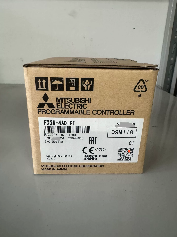
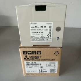
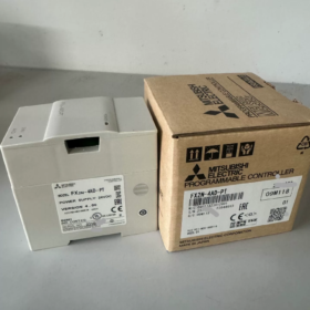
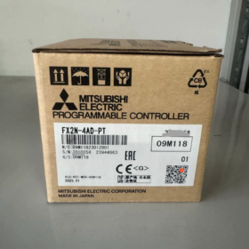
Специальный модуль расширения для ПЛК серии FX, предназначен для 4-канального 3-проводного измерения температуры PT100 с платиновым сопротивлением. Устаревший (прекращено). Связь осуществляется с помощью инструкций регистра буферной памяти FROM/TO.. 2— проводные датчики PT100 не поддерживаются..
- Декомпозиция кода модели
| Сегмент | Описание |
| FX2N | Серия ПЛК, Модуль расширения FX2N |
| 4ОБЪЯВЛЕНИЕ | 4—канальный аналоговый вход |
| ‑PT | Специальный модуль RTD для платинового сопротивления PT100; не универсальный модуль AD по напряжению/току |
- Электрическое ядро & Технические характеристики
| Элемент | Спецификация |
| Поддерживаемый датчик | 3— провод PT100 (100 Ой); модуль подает на датчик возбуждение постоянного тока 1 мА |
| Температурный диапазон | -100℃ ~ +600℃; Фаренгейт: -148℉ ~ +1112℉ |
| Формат цифрового вывода | режим ℃: значение = температура ×10 (например. 25.0 ℃ → 250); режим ℉: значение = ℉ ×10 |
| Разрешение | 0.2~0,3℃ / 0.36~0,54℉ |
| Точность | ±1% от полной шкалы |
| Время конвертации | 15 мс для всех 4 каналы |
| Разрешение AD | 12-кусочек (включая знаковый бит) |
| Источник питания на стороне ПЛК | 5 В постоянного тока, получаемое от шины расширения ПЛК, потребление 30мА; внешний 24 В постоянного тока для аналоговой схемы модуля |
| Занятые точки ввода-вывода | 8 очки (ввод или вывод, никакие физические терминалы не заняты) |
| Изоляция | Оптронная изоляция между аналоговыми и цифровыми цепями; нет изоляции между каналами |
| Масса | Приблизительно. 0.3 кг; Монтаж на DIN-рейку |
| Идентификационный код BFM#30 | К2040; читается программой для проверки наличия модуля |
| Совместимые процессоры ПЛК | FX0N/FX1N/FX2N/FX2NC/FX3G/FX3U/FX3UC; Не совместим с FX5U. |
⚠️ Жесткое ограничение: 2—провод PT100 не поддерживается. Принудительное подключение 2-проводных датчиков приведет к серьезному температурному дрейфу и неточным измерениям.. Допускается только 3-проводной RTD..
- Ключевая буферная память (БФМ) Список (ОТ = Чтение / ТО = Написать)
| БФМ | Ч/З | Описание функции |
| #0 | Вт | Стандарт ПТ100: K0 = JIS C1604-1997 (DIN3850); K1 = устаревший стандарт JIS C1604-1981. |
| #1~#4 | Вт | Усреднение количества проб для CH1‑CH4, диапазон 1-4096, по умолчанию = 8; более высокое значение = более сильная фильтрация, более медленный ответ |
| #5~#8 | Р | Средняя температура в ℃ для CH1‑CH4 (×10); обычно используется в технике |
| #9~#12 | Р | Мгновенная текущая температура в ℃ для CH1‑CH4 (×10) |
| #13~#16 | Р | Средняя температура в ℉ для CH1‑CH4 (×10) |
| #17~#20 | Р | Мгновенная текущая температура в ℉ для CH1‑CH4 (×10) |
| #21 | Вт | Напишите K1, чтобы восстановить заводскую калибровку.; регистрация автоматически очищается после этого |
| #28 | Р | Фиксация ошибки канала (обрыв провода, защелка выхода за пределы диапазона) |
| #29 | Р | Регистр состояния ошибок (критический); битовые флаги тревог |
| #30 | Р | Идентификационный код модуля K2040 для проверки модуля на стороне программы. |
Определение битов BFM29 для устранения неполадок
| Кусочек | Описание неисправности | Средство |
| б0 | Неправильная настройка параметров в BFM#0. | Установите BFM#0 на K0 или K1. |
| б1 | Счетчик усреднения № 1-#4 из диапазона 1-4096 | Изменить среднее значение выборки |
| б2 | Аппаратная неисправность, неисправность модуля | Заменить модуль |
| б10 | Цифровое значение вне диапазона (обрыв провода датчика / температура выходит за пределы диапазона) | Проверьте проводку PT100.; проверить сгоревший датчик |
- Рекомендации по подключению проводов
- 3‑провод PT100 обязателен. Три проводника должны иметь максимально одинаковое сопротивление и поперечное сечение..
- Для проводки сигнала RTD используйте экранированную витую пару.; прокладывайте отдельно от мощных кабелей, чтобы уменьшить помехи.
- Модуль питания 24 В постоянного тока; надежно заземлите клемму FG.
- Никогда не подавайте сигналы напряжения на клеммы PT., в противном случае произойдет необратимое повреждение модуля..
- Назначение номера модуля: Первый специальный модуль, расположенный рядом с ЦП, — это модуль №.0, считая вправо как номер 1, №2, №3. Первый операнд FROM/TO — это номер модуля..
Простой пример лестничной логики (Номер модуля.0, прочитать усредненное значение ℃ канала CH1 в D0)
ОТ К0 К5 Д0 К1
D0 = средняя температура CH1 ×10; например. D0=250 соответствует фактической температуре 25,0 ℃..
- Замена продукта, снятого с производства & Варианты обновления
FX2N‑4AD‑PT устарел.. Решения, сгруппированные по платформе ПЛК.
1) Сохранение платформы FX3U/FX3UC семейства FX.
- FX3U‑4AD‑PT: Прямая замена оборудования, 4—канал PT100, функциональная совместимость, Связь ОТ-ТО без изменений; требуется незначительная адаптация программы.
Примечание: FX3U‑4AD‑PT также постепенно выводится из эксплуатации..
2) Обновление до платформы FX5U
FX5‑4AD‑PT: Модуль температуры RTD, предназначенный для ЦП FX5U.
Альтернативная схема: Общий аналоговый входной модуль плюс внешний преобразователь RTD.
Совместимая замена стороннего производителя
Совместимый блок для домашнего использования: TX2N‑4AD‑PT. Совместимость по выводам с шиной расширения FX2N; отображение регистров идентично, позволяет прямую замену оборудования.
- Подводные камни выбора & Неприменимые условия
- ❌ Нельзя использовать 2-проводные датчики PT100..
- ❌ Не для входов термопар. (используйте FX2N‑4AD‑TC для термопар типа K/J.; Модули PT и TC невзаимозаменяемы.).
- ❌ Отсутствие межканальной изоляции. Синфазная разность потенциалов между несколькими точками измерения создает помехи.; требуется внешняя изоляция.
- ✅ Типичные применения: Духовки, системы очистки воды, стволы машин для литья под давлением, Холодильное хранение и другие промышленные измерения температуры в пределах -100~600℃.
- Среды с высокими помехами: Увеличьте количество усредняющих выборок в BFM1‑4. (установлен на 16‑32) для цифровой фильтрации.
- Диагностика общих неисправностей
- Исправлено чтение на уровне -1000. (-100℃) или 6000 (600 ℃): Скорее всего, обрыв провода PT100 или неправильное 3-проводное подключение.. Проверьте, включен ли BFM29 b10..
- Сильный температурный дрейф: Проверьте одинаковое сопротивление трех проводов датчика.; проверить заземление экрана; держитесь подальше от силовых кабелей.
- Все значения считываются с нуля с помощью инструкции FROM.: Неверный номер модуля; недостаточное питание шины 5 В. Считайте идентификационный код BFM30 для подтверждения связи..
- Сильные колебания чтения: Увеличьте количество усредняющих выборок в BFM1‑4..
Напоминание о различении модулей: FX2N‑4AD‑PT для термометра сопротивления PT100 и FX2N‑4AD‑TC для термопар K/J. Аппаратное обеспечение не может быть заменено.
Случаи применения FX2N‑4AD‑PT в промышленной сфере
Характеристики модуля: 4‑канальный 3-проводной сбор данных с термометра сопротивления PT100, прекращено. Обмен данными посредством инструкций FROM‑TO BFM. Подходит для многоточечного контроля температуры., обработка аварийных сигналов и ПИД-регулирование температуры с обратной связью для оборудования малого и среднего размера. Четыре практических промышленных случая ниже, включая конфигурацию оборудования, назначение точки измерения, логика процесса, ключевые фрагменты программы, указания по вводу в эксплуатацию и предупреждения о рисках на месте.
Случай 1: Многоточечный мониторинг температуры для небольших холодильных хранилищ / Чиллер (Холодильная промышленность)
Системное оборудование
ПЛК: FX2N‑32MR; Специальный модуль: FX2N‑4AD‑PT (Номер модуля.0)
Датчики: 4 кусочки 3-проводного PT100 класса A
Назначение точки измерения
CH1: Температура окружающей среды холодильного склада
CH2: Температура возвратного газа испарителя
CH3: Температура воды на выходе конденсатора
CH4: Температура охлажденной воды на выходе
Приводы: 2 компрессоры, вентилятор конденсатора, звуково-визуальная сигнализация; отображение температуры через сенсорный экран HMI
Требования к процессу
- При температуре хранения> 10 ℃: Компрессор 1 начинается; температура>12℃: Компрессор 1 + 2 работать одновременно.
- Когда температура упадет до 6℃: Остановить компрессор 1; температура падает до 3℃: Остановите оба компрессора.
- Тревога сработала при температуре<‑2℃ (сверхнизкая температура); обрыв провода датчика запускает блокировку неисправности, запрещающую запуск компрессора.
- Все значения температуры загружены в HMI; включена регистрация событий превышения лимита.
Ключевая конфигурация
- БФМ0 = К0 (Стандарт DIN PT100); БФМ1‑4 = К16 (16-усреднение выборки для подавления полевых помех внутри холодного хранилища).
- Считать среднюю температуру 4 каналы от BFM5~8 (исходное значение = температура × 10).
- Прочтите BFM29 для обнаружения обрыва провода и аппаратных неисправностей.; блокировка отключения компрессора в случае неисправности для обеспечения защиты оборудования.
Ключевой фрагмент (Лестница GX-разработчиков)
М8002 // Импульс инициализации
ОТ К0 К30 Д10 К1 // Считайте идентификационный код модуля
КМП К2040 Д10 М0 // Сравнить для проверки FX2N‑4AD‑PT
М8000
ОТ К0 К5 Д0 К4 // Считайте среднюю температуру CH1‑CH4 в D0‑D3.
ИЗ К0 К29 К4М10 К1 // Сопоставьте биты состояния ошибки с M10‑M25.
Разделите D0 на 10 чтобы получить фактическую температуру хранения; используйте инструкцию сравнения зон ZCP для логики порогового значения запуска и остановки компрессора.
Риски на месте
В холодильной камере влажность; держите клеммные колодки PT100 влагонепроницаемыми. 2‑проволока PT100 строго запрещена из-за сильного сноса. Нет межканальной изоляции; применять одноточечное заземление экрана, если несколько щупов имеют общую опорную землю.
Случай 2: Контроль температуры для резервуара для пастеризации пищевых продуктов (Пищевая промышленность)
Конфигурация оборудования
ПЛК FX2N‑64MR; FX2N‑4AD‑PT (Номер модуля.0); Модуль аналогового вывода FX2N‑4DA
3 кусочки 3‑проводного PT100:
CH1: Температура материала внутри резервуара (Обратная связь основного управления ПИД-регулятора)
CH2: Температура воды на входе в теплообменник
CH3: Температура выпускного отверстия
CH4: Запасной канал
Приводы: Твердотельное реле SSR для электрообогрева; циркуляционный насос; выпускной перепускной клапан; ПИД-регулятор с обратной связью через инструкцию FNC88.
Требования к процессу
- Нагрейте материал до 92℃ и удерживайте 15 секунд.. Открыть выпускной клапан при достижении заданного значения.; отводить неквалифицированный материал на рециркуляцию.
- Разряд запрещен при температуре <85℃.. Немедленно отключить теплоотдачу, включить систему сигнализации и остановки при обрыве провода PT100, чтобы предотвратить опасность сухого ожога.
- HMI отображает три значения температуры; регистрация данных процесса для удовлетворения требований соответствия HACCP.
Основные моменты программы
- Д0 (Чтение канала 1) служит в качестве PID PV (переменная процесса, исходное значение ×10); уставка SV = 920 представляет 92,0 ℃.
- Выходной сигнал ПИД отправляется на FX2N‑4DA, генерирование аналогового сигнала 0–10 В для регулирования мощности твердотельного реле.
- Когда БФМ29 b10 (флаг обрыва провода) включен: сброс выхода ПИД-регулятора и принудительное отключение выхода нагрева Y0.
Замечания по вводу в эксплуатацию
Нагревательный контур имеет большую тепловую инерцию. & отставать; итеративно настраивать параметры P/I/D PID. Увеличьте счетчик усреднения BFM1, чтобы снизить шум поля, вызванный двигателем..
Случай 3: Многоточечное измерение температуры в сушильной печи в упаковке & Печатное оборудование
Аппаратное обеспечение
FX2N‑48MR + FX2N‑4AD‑PT
CH1: Температура на входе в печь
CH2: Средняя часть духовки (главный пункт управления технологическим процессом)
CH3: Температура на выходе из духовки
CH4: Температура выхлопного воздуха
Приводы: Нагревательные элементы с контакторным управлением; блокировка вентилятора; отключение отопления при перегреве.
Логика процесса
- Постоянный контроль температуры с регулируемой уставкой 80‑130℃, использование температуры в середине духовки CH2 в качестве основной обратной связи.
- Включите блокировку перегрева и отключите всю мощность нагрева, если температура на выходе > 150 ℃.; включение обогрева запрещено, если вентилятор неисправен.
- Загрузите четыре температурные точки в HMI и зарегистрируйте события перегрева..
Инженерные примечания
Высокая температура окружающей среды вокруг духовки; использовать экранированные кабели, рассчитанные на высокие температуры, для датчиков PT100. Отделите сигнальные кабели от силовых кабелей с минимальным зазором ≥20 см.. Установите фильтр на блок питания 24В модуля..
>⚠️ Не применимо при температуре выше 600 ℃. (верхний предел диапазона измерения модуля). Вместо этого используйте модуль термопары FX2N‑4AD‑TC для применений с более высокими температурами..
Случай 4: Мониторинг температуры для небольшого химического реактора с перемешиванием (Тонкая химическая промышленность)
Конфигурация оборудования
FX2N‑48MR, FX2N‑4AD‑PT; 4‑канальный 3-проводной PT100
CH1: Температура материала внутри реактора (главный контроль)
CH2: Рубашка температуры нагревательной среды
CH3: Температура охлаждающей воды на выходе
CH4: Температура внешней стенки реактора
Выходы: Электромагнитный клапан отопления, Электромагнитный клапан охлаждающей воды, двигатель мешалки, выход тревоги.
Логика процесса
- Открыть отопительный клапан во время фазы нагрева; закрытие нагрева при достижении заданной температуры; автоматически открывающийся клапан охлаждающей воды для защиты от перегрева.
- Система переходит в безопасное состояние при обрыве любого провода датчика.: закрыть кран отопления, открытая охлаждающая вода, активировать звуково-визуальную сигнализацию.
- Многоканальное сравнение температур для сигнализации о чрезмерной разнице температур между внутренней частью реактора и рубашкой, во избежание локального перегрева.
Соображения риска
Коррозионная атмосфера внутри химического завода; использовать антикоррозионные защитные втулки для датчиков PT100. Нет межканальной изоляции; потенциальное колебание показаний, вызванное смещением потенциала земли между точками измерения; реализовать одностороннее заземление на стороне датчика.
Общие правила инженерной реализации (Общее в четырех случаях)
- Проверка номера модуля: Первый специальный модуль, соседний с CPU = K0, увеличить до K1/K2 вправо. Первый операнд FROM/TO должен соответствовать номеру физического модуля.. Считайте BFM30 = K2040 для проверки конфигурации оборудования..
- Электромонтажная дисциплина: Используйте только 3-проводные датчики PT100.. Соответствие трехпроводному сопротивлению; одноточечное заземление для экрана; строго запрещать подачу напряжения на клеммы датчика.
- Шаблон обработки ошибок: Чтение BFM29 в каждом цикле сканирования.. b10 ON указывает на обрыв провода канала.. Программа должна реализовывать защитную блокировку, а не только сигнализацию.; сократить подачу тепла во избежание несчастных случаев.
- Преобразование чтения: Необработанное значение регистра = фактическая температура × 10; например. `D0=250 →25,0℃`.
- Руководство по обновлению прекращено: Для существующей системы FX2N при переходе на FX3U: выберите FX3U‑4AD‑PT. Для миграции FX5U: принять FX5‑4AD‑PT.



NH42-63-318x560.png "Автоматические переключатели резерва типа PC CHINT (АТС)НХ42-63/4СЗ")



