 Контактор,автоматический выключатель,солнечный инвертор,электрический счетчик,солнечные батареи

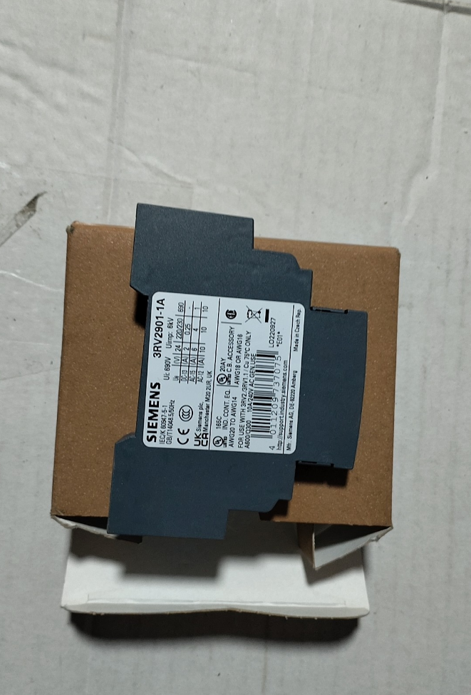

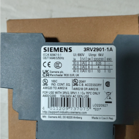
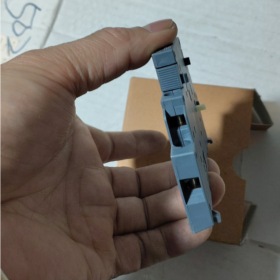
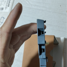

The 3RV2901-1A is a side-mounted passive auxiliary contact module под Сименс SIRIUS modular system, serving as a standard extension accessory for 3RV2 series motor protection circuit breakers. Equipped with a built-in combination of 1 Нормально открытый (НЕТ) + 1 Нормально закрытый (Северная Каролина) contacts and screw-clamp terminals, this module enables functions including circuit breaker open/closed status feedback, fault trip signal output, electrical interlocking of control circuits, and remote signal acquisition by PLC. It is widely applied in industrial power distribution scenarios such as motor starting protection, signal indication in power distribution cabinets, and safety interlock circuits.
- Model Coding Breakdown
| Сегмент кода | Описание |
| 3RV2 | Main product line code for Siemens SIRIUS series motor protection circuit breakers, identifying the product system it belongs to |
| 901 | Product family code for side-mounted auxiliary contacts, differentiated from other circuit breaker accessories such as front-mounted contacts, fault signal contacts and undervoltage releases |
| 1А | Specification version identifier: “1” stands for 1NO+1NC contact configuration; “А” denotes screw-clamp wiring terminals |
III. Основные технические характеристики
| Параметр Элемент | Спецификация Значение |
| Тип продукта | Side-mounted auxiliary contact module for circuit breakers |
| Конфигурация контактов | 1 Нормально открытый (НЕТ) + 1 Нормально закрытый (Северная Каролина), passive dry contacts |
| Compatible Products | 3RV2 series motor protection circuit breakers (all frame sizes S00 ~ S3) |
| Номинальное напряжение изоляции Ui | 690 В и |
| Номинальное импульсное выдерживаемое напряжение Uimp | 6 кВ |
| Conventional Thermal Current Ie | 10 A AC |
| Rated Current for Utilization Category AC-15 | 6 A @ 24 В и; 4 A @ 230 В и; 3 A @ 400 В и; 1 A @ 690 В и |
| Rated Current for Utilization Category DC-13 | 2 A @ 24 В Вашингтоне; 0.5 A @ 110 В Вашингтоне; 0.25 A @ 250 В Вашингтоне |
| Способ подключения | Винтовые зажимы |
| Класс защиты | IP20 (finger-safe protection) |
| Ambient Operating Temperature | -20℃ ~ +60 ℃ |
| Способ монтажа | Snap-on mounting on the side of circuit breaker |
| Net Weight per Unit | 0.045 кг |
| Сертификаты соответствия | МЭК 60529; supports marine, railway, KC and other industry certifications |
- Terminal Pin Definition
The module has 4 клеммы проводки всего. Contact numbers comply with the standard naming rules of Siemens industrial control components. Passive contacts have no distinction between input and output, and the definitions are as follows:
| Терминал №. | Contact Belonged To | Описание функции |
| 33 | Нормально открытый (НЕТ) | First terminal of NO contact; conducts with terminal 34 when the circuit breaker is closed |
| 34 | Нормально открытый (НЕТ) | Second terminal of NO contact; disconnects from terminal 33 when the circuit breaker is open |
| 41 | Нормально закрытый (Северная Каролина) | First terminal of NC contact; conducts with terminal 42 when the circuit breaker is open |
| 42 | Нормально закрытый (Северная Каролина) | Second terminal of NC contact; disconnects from terminal 41 when the circuit breaker is closed |
- Compatible Product Range
Full-series compatibility: 3RV2 series motor protection circuit breakers covering four standard frame sizes S00, S0, С2, S3
Corresponding circuit breaker model series: 3RV20 (S00 frame), 3RV21 (S0 frame), 3RV23 (S2 frame), 3RV24 (S3 frame)
Maximum 2 modules can be installed laterally on one circuit breaker (1 piece on left and 1 on right side), поддержка до 2 groups of extended contacts
- Installation and Operation Specifications
- Hardware Installation Steps
- Ensure the main circuit and control circuit of the circuit breaker are fully powered off without residual voltage.
- Align the auxiliary contact module with the mounting guide groove on the side of the circuit breaker, push it vertically until the buckle locks tightly, and confirm the transmission lever is fully engaged with the circuit breaker mechanism.
- Strip 5~7 mm insulation layer of control cables, connect wires to corresponding terminals by number, and the recommended tightening torque for screws is 0.8~1.2 N·m.
- После установки, manually open and close the circuit breaker, and verify contact action logic and continuity with the continuity test range of a multimeter.
- Меры предосторожности при эксплуатации
The module adopts passive dry contacts. Do not connect power circuits directly; it is only applicable to control and signal circuits.
When driving inductive loads (contactor coils, intermediate relays), it is recommended to connect surge suppression components (RC circuits or diodes) in parallel to suppress back EMF and extend contact service life.
The actual load current shall not exceed the rated operating current under the corresponding voltage level to avoid contact overheating, ablation and adhesion failure.
VII. Матрица поиска и устранения распространенных неисправностей
| Явление неисправности | Анализ первопричин | Пошаговые решения |
| No signal output from contacts; status does not switch with circuit breaker operation | 1. Module not fully snapped in, transmission lever disengaged from breaker mechanism | 1. Выключить питание, reinsert the module, confirm full buckle locking and normal transmission stroke |
| 2. Poor contact caused by loose wiring or oxidized terminals | 2. Затяните клеммы проводки, polish oxidized contacts and re-test cable continuity | |
| 3. Contact ablation and adhesion due to overload | 3. Replace the contact module and check whether the load power exceeds rated value | |
| False signal triggering, frequent status fluctuation | 1. Severe electromagnetic interference from power cables on control wires | 1. Separate wiring of control cables and power cables, reliably ground the shield at one end only |
| 2. Electric leakage caused by damaged cable insulation or dust accumulation between terminals | 2. Replace damaged cables, clean terminal dust and measure insulation resistance | |
| 3. Poor contact induced by cabinet vibration | 3. Fasten mounting fasteners of circuit breaker and module; add shock absorption measures if necessary | |
| NC contacts fail to open after circuit breaker closing | 1. Offset module mounting leading to insufficient actuation stroke of transmission lever | 1. Recalibrate module mounting position to ensure full mechanical engagement |
| 2. Mechanical jamming of contacts or failure of internal reset spring | 2. Replace the entire auxiliary contact module; disassembly and maintenance of internal structure by users are prohibited |
VIII. Model Comparison of Auxiliary Contacts in the Same Series
| Модель | Конфигурация контактов | Способ подключения | Основные различия |
| 3RV2901-1A | 1НЕТ + 1Северная Каролина | Винтовые клеммы | Universal side-mounted type, the most widely used standard specification |
| 3RV2901-2A | 2НЕТ | Винтовые клеммы | Side-mounted with dual NO contacts, suitable for multi-channel signal feedback applications |
| 3RV2901-3A | 2Северная Каролина | Винтовые клеммы | Side-mounted with dual NC contacts, suitable for safety interlock circuits |
| 3RV2901-1D | 1НЕТ + 1Северная Каролина | Spring terminals | Side-mounted, tool-free quick connection, suitable for high-frequency maintenance scenarios |
Operating Principle of 3RV2901-1A
The 3RV2901-1A is a pure mechanical linkage passive dry contact auxiliary contact module. Its core operating principle relies on rigid mechanical coupling with the operating mechanism of the 3RV2 circuit breaker main body, converting the physical open/closed position of the breaker main contacts into on/off signals of electrical contacts. No additional operating power supply is required throughout operation, making it a passive status feedback component.
- Mechanical Linkage Transmission Principle
This is the core driving mechanism of the module, fully driven by mechanical movement of the circuit breaker without participation of electronic components:
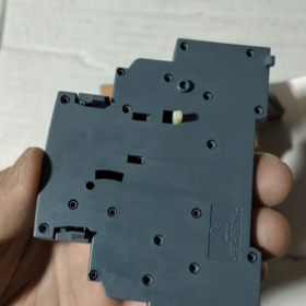
- Rigid Coupling Structure: After the module is snap-mounted on the breaker side, its internal transmission driving lever is precisely embedded into the linkage slot of the breaker operating spindle, forming synchronous rigid linkage with the main contact mechanism of the circuit breaker, delivering delay-free and deviation-free action.
- Power Source for Action: When the circuit breaker is closed, opened or tripped by fault, the angular displacement of the main contact rotating shaft directly pushes the module’s transmission lever and drives the internal moving contact bracket to displace, realizing switching of contact status. Under open state, the built-in reset spring inside the module maintains the initial contact status.
- Essence of Passive Feature: The module itself has no power supply circuit or signal processing circuit. Contacts are only driven by mechanical force, so it boasts strong anti-electromagnetic interference performance and high reliability, and can operate stably in industrial environments with heavy electromagnetic disturbance.
- Electrical Operating Logic of Contacts
The module is equipped with one set of passive dry contacts (1НЕТ + 1Северная Каролина). Contact status strictly corresponds to the position of the circuit breaker main contacts, irrelevant to the trigger cause of opening (manual opening / overload trip / short-circuit trip). The specific status correspondence is as follows:
| Circuit Breaker Status | Нормально открытый контакт (НЕТ, Терминалы 33-34) | Нормально закрытый контакт (Северная Каролина, Терминалы 41-42) |
| Open state (initial normal state, including after manual opening or fault trip) | Открыть | Closed |
| Closed state (normal closing, maintained engagement) | Closed | Открыть |
Key Electrical Feature Description
The contacts are passive dry contacts with no built-in power. Во время использования, a control power supply and load shall be connected in series to the external circuit, compatible with various AC and DC control circuits.
The breaking capacity of contacts is only applicable to control-level loads (utilization category AC-15/DC-13). Direct connection to main power circuits is forbidden; в противном случае, insufficient arc extinguishing capacity will lead to contact ablation and adhesion failure.
III. Realization Principle of Typical Functions
- Remote Feedback of Circuit Breaker Status
Connect PLC input points and status indicator lamps in series to the NO contact circuit: when the circuit breaker is closed, the NO contact closes and the circuit conducts, the PLC collects level signals and the indicator lamp lights up to intuitively feedback the running status “circuit breaker closed”; when the breaker opens or trips by fault, the NO contact opens and signals disappear, which can trigger upper computer shutdown alarms.
- Electrical Safety Interlock
Connect NC contacts in series to the closing control circuit of adjacent circuits to realize hard electrical interlock between two motors or two power supplies: when this circuit breaker is closed, the NC contact opens and forcibly cuts off the closing control path of the other circuit, avoiding faults such as short circuit and mechanical interference caused by simultaneous closing of two circuits, with much higher reliability than software logic interlock.
- Linked Shutdown upon Fault
When the circuit breaker trips due to overload or short circuit faults, the main contacts separate and the auxiliary contacts reset synchronously. The NO contacts open to directly cut off the enable circuits of contactors and inverters, realizing rapid shutdown protection under fault conditions without extra detection components.
- Core Principle Difference from Fault Signal Contacts
Ordinary position auxiliary contacts and fault signal contacts are easily confused, and there are essential differences in their operating mechanisms:
This product (3RV2901-1A, position auxiliary contact): Only acts following the physical position of main contacts. It cannot distinguish manual opening and fault tripping. Once the main contacts separate, the contacts return to the initial state.
Fault signal contacts (например. 3RV2901-2E): Equipped with an internal trip memory mechanism. They only act when the circuit breaker trips due to overload or short-circuit faults, and will not be triggered by normal manual opening, specially used for fault alarm identification.


 Импульсный термосварочный регулятор температуры")


")


NH42-63-318x560.png "Автоматические переключатели резерва типа PC CHINT (АТС)НХ42-63/4СЗ")


