 คอนแทคเตอร์,เบรกเกอร์,เซ็นเซอร์,ตัวเข้ารหัส,บมจ,ตัวแปลง

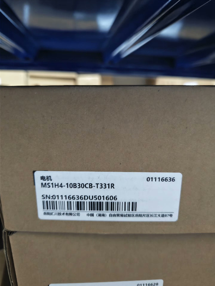

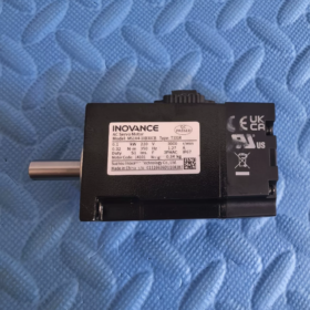
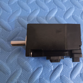
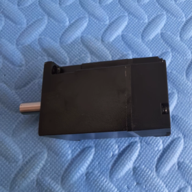
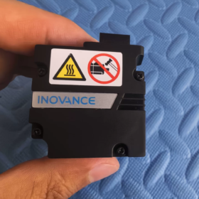
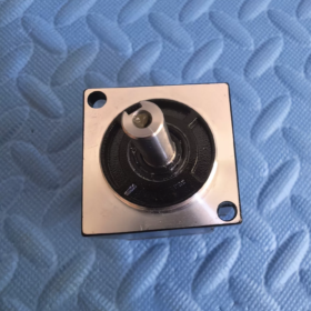
MS1H4-10B30CB-T331R
| เซ็กเมนต์ | คำนิยาม |
| MS1 | MS1 Series General เซอร์โวมอเตอร์ |
| H4 | Medium Inertia, Small Capacity |
| 10บี | ระดับพลังงาน: 10×10 = 100W (0.1กิโลวัตต์) |
| 30ค | ความเร็วสูงสุด: 30×100 = 3000 รอบต่อนาที |
| บี | ระดับแรงดันไฟฟ้า: Single/Three-phase AC220V |
| T3 | 18-bit Multi-turn Absolute ตัวเข้ารหัส |
| 3 | Shaft Configuration: With Keyway + Internal Thread at Shaft End |
| 1 | อุปกรณ์เสริม: With Oil Seal, Without Electromagnetic Holding Brake |
| ร | Standard Flange Version |
Distinction Note: A3 = 23-bit multi-turn absolute encoder; T3 = 18-bit multi-turn absolute encoder. The cables are mechanically interchangeable, but resolution differs; parameters must not be used without reconfiguration.
- ข้อมูลจำเพาะทางไฟฟ้าหลัก
| รายการ | ค่า |
| กำลังไฟพิกัด | 100ว / 0.1กิโลวัตต์ |
| แรงบิดสูงสุด | 0.32 น.ม |
| แรงบิดสูงสุด | 1.12 น.ม (350% โอเวอร์โหลด) |
| ความเร็วสูงสุด | 3000 รอบต่อนาที |
| ความเร็วสูงสุด | 7000 รอบต่อนาที |
| จัดอันดับปัจจุบัน | 1.27 ก |
| กระแสสูงสุด | 4.78 ก |
| โมเมนต์ความเฉื่อยของโรเตอร์ | 0.072 ×10⁻⁴ กก.·ตร.ม |
| Frame Flange Size | 40 มม |
| ตัวเข้ารหัส | 18bit Multi-turn Absolute Encoder |
| Holding Brake | Not Equipped |
| ระดับการป้องกัน | IP67 (Excluding Shaft Seal Area) |
| Duty Type | S1 Continuous Operation |
- Compatible Servo Drives
✅ Recommended Matches:
SV660PS Series (กระแสหลัก)
SV670PS Series
Not directly compatible with legacy IS620 drives. Encoder adapter cable is mandatory if IS620 is used.
- การใช้งานทั่วไป
Small positioning equipment, 3C automation equipment, miniature conveying mechanisms, fine-tuning platforms, linear modules, dispensing machines, inspection slides, small indexing units.
- Derivative Model Comparison (For Procurement & การทดแทน)
MS1H4-10B30CB-A331R: 23-ตัวเข้ารหัสสัมบูรณ์แบบหลายเลี้ยวบิต (High Precision Version)
MS1H4-10B30CB-T32R: With holding brake and oil seal
MS1H4-10B30CB-T30R: Without oil seal and holding brake
- การคัดเลือก & ข้อควรระวังในการเปลี่ยน
- This model has no holding brake. Do not use it for vertical axis loads; select T32R brake-equipped variant for vertical applications.
- T3 (18-นิดหน่อย) and A3 (23-นิดหน่อย) encoders share identical connector interfaces. Encoder type must be reconfigured in drive parameters after motor replacement.
- ความเร็วสูงสุด 7000 รอบต่อนาที; sustained operating speed ≤6000 rpm is recommended to avoid excessive temperature rise.
- Shaft design: Keyway + internal shaft-end thread. Check coupling dimensions during replacement.
INOVANCE MS1H4-10B30CB-T331R (40 กรอบ, 100ว, ไม่มีเบรก) ขนาดเค้าร่าง
หน่วย: มม, This model = Non-brake version; dimensions inside brackets represent total length of T32R brake-equipped variant.
- ขนาดการติดตั้งโดยรวม
| เครื่องหมาย | คำอธิบาย | ค่า | ความอดทน |
| ลค | Square Flange Mount Base Width | 40 | มาตรฐาน 40 กรอบ |
| ที่ | Flange Outer Diameter | 46 | — |
| LL | Overall Motor Length (Flange Surface to Rear End) | 91 | Brake version: 121.5 |
| แอล.อาร์ | Shaft Protrusion Length (Flange face to shaft end) | 25 | ±0.3 |
| ปอนด์ | Output Shaft Diameter | Φ30 h7 | 0/-0.021 |
| แอลจี | Keyway Depth | 5 | — |
| ที่ | Keyway Width | 2.5 | ±0.5 |
| LJ | Shaft End Chamfer | 0.5 | ±0.35 |
| LZ | Mounting Through Hole | 2×Φ4.5 | Diagonally Arranged |
| แอล.เอช | Mounting Hole Center Distance | 34.3 | — |
- Output Shaft Details (Keyway + Shaft Internal Thread, คำต่อท้าย “3” Shaft Specification)
- เส้นผ่านศูนย์กลางเพลา: Φ30h7
- Parallel Key Size: Width 2.5mm, Depth 5mm
- ปลายเพลา: Internal threaded hole (for coupling retaining ring/positioning)
- Shaft Extension Length: 25มม
- Allowable Shaft Loads
Allowable Radial Load: 120 เอ็น (at shaft end)
Allowable Axial Load: 40 เอ็น
⚠️ Overload will accelerate bearing wear and shorten service life.
- น้ำหนัก
MS1H4-10B30CB-T331R (ไม่มีเบรก): 0.75 กก
Derivative T32R (พร้อมระบบเบรก): 0.98 กก
- Key Assembly Notes
- Protection Class IP67: Shaft oil seal region and electrical connectors are excluded from IP67 rating. Avoid permanent water immersion.
- การติดตั้ง: การติดตั้งหน้าแปลนด้านหน้า; recommended fastener M4, tightening torque 1.2~1.5 N·m
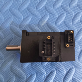
- ขั้วต่อ: Power and encoder connectors are laterally arranged at motor rear. Reserve clearance in equipment design.
- Mechanical Interchange Warning: Brake-equipped variant T32R overall length 121.5mm; cannot be directly interchanged without modifying mechanical frame.
- Matching Cable Part Numbers (การจัดหาชิ้นส่วนอะไหล่)
สายไฟ: S6-L-M04-xxx (40-frame power cable)
Encoder Cable for 18-bit Multi-turn Absolute: S6-E-T3-xxx
Not directly compatible with cables defined for A3 encoder.
INOVANCE MS1H4-10B30CB-T331R (40 กรอบ, 100ว, ไม่มีเบรก) Complete Installation Specification
- Basic Mounting Type
Standard Mounting: Front Flange Mount (IEC B3 Flange)
Only flange-face mounting is supported; no foot-mount structure. Square flange dimension 40mm.
Suffix R = Standard flange version; Solid shaft with parallel key and internal thread on shaft end.
- Fastener Specification (วิกฤต)
- รูยึด: 2 diagonally distributed Φ4.5 through holes
- Recommended bolt: M4 Hex Socket Head Cap Screw (Grade ≥8.8)
- แรงบิดขันมาตรฐาน: 2.4 น.ม
✅ Operation Rule: Tighten diagonally in multiple passes. Avoid one-sided full tightening to prevent flange distortion.
- Mounting Reference Plane: Motor front flange surface; flatness ≤0.02mm.
- Allowable Mounting Orientations
| การวางแนวการติดตั้ง | Permissibility | ข้อกำหนดบังคับ |
| Horizontal Mount (Shaft Horizontal) | ✅แนะนำ | Optimal heat dissipation; no extra constraints |
| Vertical Mount Shaft Downward (Load Hanging Down) | ✅ Permitted | Reserve clearance for cable connectors; No holding brake – Do NOT suspend loads when power is off. |
| Vertical Mount Shaft Upward (Load Facing Up) | ⚠️ Not recommended for long-term operation | Accelerated front oil seal aging; only applicable for short-cycle equipment. |
| Inclined Mount (Any Angle) | ✅ Permitted | Arrange connectors downward to avoid condensed water ingress. |
Important Warning: No electromagnetic holding brake fitted. Strictly forbidden for vertical lifting loads. Select T32R brake-equipped model for vertical axes!
- Motor Shaft to Load Connection Specification
4.1 Shaft Parameter Recap
Shaft diameter Φ30 h7; shaft extension 25mm; parallel key width 2.5mm; internal thread at shaft end.
4.2 Coupling Installation Rule
❌ Never strike motor shaft end directly with hammer!
Impact will damage encoder magnetic ring and permanently disable the motor.
✅ Correct practice: Use hydraulic fitting tools, thermal assembly (temperature ≤80℃), or screw jack method to press-fit coupling.
4.3 Coaxiality Tolerance
Max allowable radial offset: ≤0.03 mm
Max angular misalignment: ≤0.5°
Recommended Coupling: Jaw flexible coupling / Diaphragm coupling
Excessive misalignment causes vibration, premature bearing wear and high-speed noise.
4.4 Continuous Allowable External Load
Allowable radial load at shaft end: 120 เอ็น
Allowable axial load at shaft end: 40 เอ็น
Belt drive and gear drive generate continuous radial forces; load calculation is mandatory to avoid exceeding limits.
- การกระจายความร้อน & Installation Clearance
- วิธีการทำความเย็น: Natural Convection Cooling. Reserve ≥30mm free space around cooling fins.
- Do not attach motor rear end directly to sheet metal or closed cover.
- Derate motor output when ambient temperature continuously exceeds 40°C; derate power for altitude >1000ม.
- Maximum permissible housing surface temperature during operation: ≤120°C.
- ตัวเชื่อมต่อ & Cable Routing Rules
- Power and encoder connectors are located on the side of motor rear. Reserve cable movement space in mechanical design.
- Cable Strain Relief: Install cable clamp adjacent to connectors to prevent tension from cable weight pulling connectors.
- การแยกสายไฟ: Separate power cables and shielded encoder cables; maintain ≥30cm parallel distance. Cross cables at 90° where possible.
- Waterproof for Connectors: Ensure plugs are fully locked. Avoid upward-facing connectors inside equipment to prevent water accumulation. IP67 rating applies only to motor housing; connectors are not IP67 sealed.
- Grounding Specification
- Reliably connect motor housing PE terminal to protective earth.
- Shield layers of power cable and encoder cable shall be grounded at both ends to cabinet ground busbar per Inovance standard.
- Ground resistance <100Ω to prevent encoder position drift and communication faults caused by electromagnetic interference.
- ข้อห้ามในการติดตั้ง (Mandatory Rules)
- Welding or spot welding on motor housing is prohibited; high temperature will destroy internal encoder.
- Grinding or machining on motor flange and shaft is forbidden.
- Avoid prolonged motor stall operation.
- Prevent continuous flushing of shaft oil seal with cutting fluid or oil contamination.
- Do not lift/move motor by cables or connectors during handling; grip only the flange housing.
- Standard Installation Procedure
- Clean mounting base, remove burrs and metal chips.
- Attach motor flange to mounting surface, insert M4 bolts and apply diagonal pre-tightening.
- Secure motor temporarily and assemble coupling.
- Adjust motor position and verify coaxiality with dial indicator.
- Tighten bolts to specified torque of 2.4 N·m in diagonal sequence.
- Install cable brackets, connect power cable and encoder cable.
- Check for mechanical interference and cable tension risks before power-on commissioning.





NH42-63-318x560.png "สวิตช์ถ่ายโอนอัตโนมัติชนิด CHINT PC (เอทีเอส)NH42-63/4SZ")



