 คอนแทคเตอร์,เบรกเกอร์,เซ็นเซอร์,ตัวเข้ารหัส,บมจ,ตัวแปลง

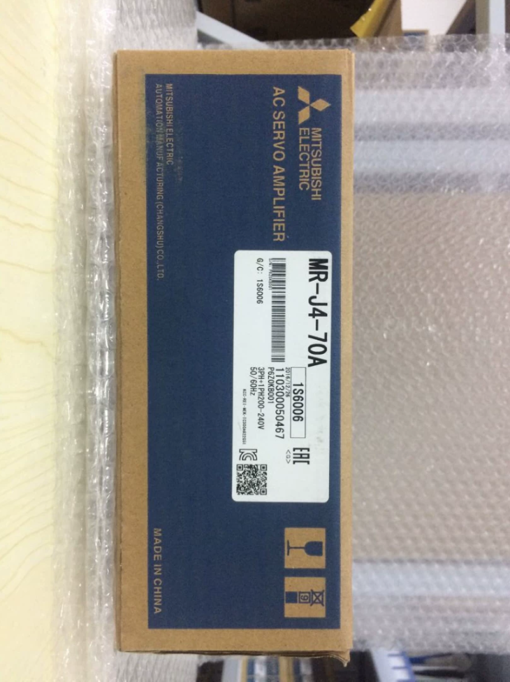

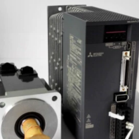
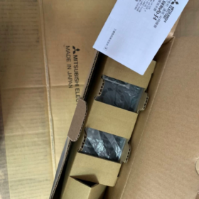
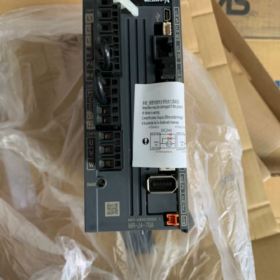
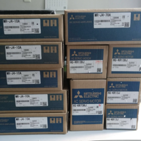
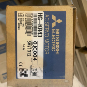
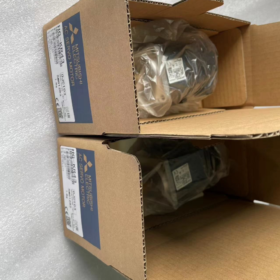
ซีรี่ส์ MELSERVO-J4, 750ว (0.75 กิโลวัตต์), 200-อินพุตพัลส์อเนกประสงค์คลาส V เซอร์โวแอมพลิฟายเออร์
คำจำกัดความของโมเดล
MR-J4: มิตซูบิชิ 4เซอร์โวซีรีส์ยุคใหม่
70: กำลังมอเตอร์ที่ตรงกัน: 750 ว
ก: อินเตอร์เฟซวัตถุประสงค์ทั่วไป (ชีพจร + อินพุตแบบอะนาล็อก). ไม่ใช่ประเภทไฟเบอร์บัส SSCNET. ยอมรับคำสั่งพัลส์จาก บมจ. รุ่น -B ติดตั้งอินเทอร์เฟซบัสไฟเบอร์ออปติก SSCNET III/H.
ข้อมูลจำเพาะทางไฟฟ้าหลัก
| รายการ | ข้อมูลจำเพาะ |
| อินพุตกำลังไฟของวงจรหลัก | เฟสเดียว / สามเฟส AC200‑240V, 50/60 เฮิรตซ์ |
| ช่วงอินพุตที่อนุญาต | ไฟฟ้ากระแสสลับ170‑264V |
| จัดอันดับกระแสไฟขาออก | 4.0 ก; กระแสสูงสุด: 12 ก (1 ส) |
| ควบคุมแหล่งจ่ายไฟ | DC24V ± 10%, ประมาณ. 0.5 ก |
| โหมดการควบคุม | ตำแหน่ง (สูงสุด. ชีพจรอินพุต: 4 MPS), ความเร็ว, แรงบิด |
| ฟังก์ชั่นความปลอดภัย | สทีโอ (ปิดแรงบิดที่ปลอดภัย) |
| ส่วนประกอบออนบอร์ด | ตัวต้านทานแบบรีเจนเนอเรชั่นในตัว, เบรกแบบไดนามิก |
| ซอฟต์แวร์กำหนดค่า | MR-ตัวกำหนดค่า2, พอร์ตดีบัก USB |
ข้อมูลจำเพาะทางกล
ขนาด: ก60×ส168×ล185มม
น้ำหนัก: 1.4 กก
การติดตั้ง: การติดตั้งราง DIN แนวตั้งภายในตู้, IP20
อุณหภูมิในการทำงาน: 0-55 องศาเซลเซียส, ไม่มีการควบแน่น
มอเตอร์ที่ใช้ร่วมกันได้ (ชุดค่าผสมมาตรฐาน)
HG-KR73: 750 ว, ความเฉื่อยต่ำ, ไม่มีเบรก
HG-KR73B: 750 ว, ความเฉื่อยต่ำ, พร้อมเบรกแม่เหล็กไฟฟ้า
HG-SR73: 750 ว, ความเฉื่อยปานกลาง
บันทึก: ต้องจับคู่แอมพลิฟายเออร์และตัวเข้ารหัสมอเตอร์. ไดรฟ์ MR-J4 ไม่สามารถใช้งานมอเตอร์ซีรีส์ MR-J3 ได้โดยตรง.
ภาพรวมตัวเชื่อมต่อ
- ซีเอ็น1: สัญญาณ I/O ดิจิตอล, อินพุตความปลอดภัย STO
- ซีเอ็น2: อินเทอร์เฟซตัวเข้ารหัสเซอร์โวมอเตอร์
- ซีเอ็น3: ชีพจร / อินพุตคำสั่งแบบอะนาล็อก (สำหรับโฮสต์ PLC)
- ซีเอ็น4: พอร์ตดีบัก USB สำหรับการตั้งค่าพารามิเตอร์พีซี
- CN5: เอาต์พุตมอนิเตอร์แบบอะนาล็อก
- U/วี/วัตต์: กำลังส่งออกไปยังเซอร์โวมอเตอร์
ความเข้ากันได้ทดแทน
- อัปเกรดภายในกลุ่มผลิตภัณฑ์เดียวกัน
MR-J4-70A → MR-J5-70A (เซอร์โวชนิดพัลส์เจเนอเรชั่นใหม่). ฮาร์ดแวร์ pin-out เข้ากันไม่ได้; จำเป็นต้องปรับโปรแกรมใหม่.
- ทดแทนหน่วยเดิม
ชุดติดตั้งเพิ่ม MR-J3-70A: MR-J4-70A มีความเข้ากันได้ในการใช้งาน, แต่ขนาดการติดตั้งและสายไฟไม่สามารถใช้แทนกันได้ทั้งหมด; จะต้องเปลี่ยนสายเคเบิล.
- การเปรียบเทียบประเภทรถบัส
MR-J4-70A: ชีพจร / อินเตอร์เฟซแบบอะนาล็อก; MR-J4-70B: ไฟเบอร์บัส SSCNET. ไม่ใช่การเปลี่ยนพินต่อพินโดยตรง.
การใช้งานทั่วไป
เครื่องแกะสลัก, ผู้ติดฉลาก, กลไกการขนถ่ายวัสดุ, อุปกรณ์บรรจุภัณฑ์, แกนป้อนเครื่องมือกล. เหมาะสำหรับระบบ PLC ที่มีความสามารถในการเอาต์พุตพัลส์.
การแก้ไขปัญหา & หมายเหตุการบำรุงรักษา
- ALM32: กระแสเกิน. ตรวจสอบการลัดวงจรของมอเตอร์ U/V-W หรือการรั่วไหลของกราวด์.
- ALM50: โอเวอร์โหลด. ตรวจสอบการติดขัดของกลไกหรือการจับคู่ความเฉื่อยที่ไม่ดี.
- อลา.E6: การสื่อสารตัวเข้ารหัสล้มเหลว. ตรวจสอบสายเคเบิลตัวเข้ารหัส CN2.
- โอเวอร์โหลดการปฏิรูป: การเร่งความเร็ว/การลดความเร็วอย่างรวดเร็วบ่อยครั้งต้องใช้ตัวต้านทานที่สร้างใหม่จากภายนอก.
รหัส HS ศุลกากร: 8501520000
คู่มือการติดตั้งฉบับสมบูรณ์สำหรับ Mitsubishi MR-J4-70A
⚠️คำเตือนด้านความปลอดภัย: การเดินสายและการถอดชิ้นส่วนทั้งหมดจะต้องดำเนินการโดยถอดกำลังไฟออกจนสุด. รออย่างน้อย 15 นาทีจนกระทั่งไฟชาร์จดับลง. ตรวจสอบว่าไม่มีไฟฟ้าแรงสูงตกค้างระหว่าง P+-N- ขั้วต่อด้วยมัลติมิเตอร์เพื่อหลีกเลี่ยงไฟฟ้าช็อต. งานจะต้องดำเนินการโดยช่างไฟฟ้าที่มีคุณสมบัติเหมาะสม.
MR-J4-70A: 750 ว, 200-เครื่องขยายสัญญาณเซอร์โวอินพุตพัลส์ V, รองรับไฟ AC200-240V เฟสเดียวหรือสามเฟส.
- การติดตั้งเครื่องกลของตู้
1.1 สภาพแวดล้อมการติดตั้ง
ติดตั้งในแนวตั้งภายในตู้ควบคุม. ห้ามวางราบหรือติดตั้งกลับหัว.
อุณหภูมิแวดล้อม: 0-55 องศาเซลเซียส, ไม่มีการควบแน่น; ระดับความสูง ≤1,000ม; ปราศจากฝุ่น, หมอกน้ำมันและก๊าซที่มีฤทธิ์กัดกร่อน.
วิธีการติดตั้ง: การขันสกรูหรือการติดตั้งราง DIN.
1.2 ช่องว่างการระบายความร้อน (วิกฤต)
ระยะห่างด้านบน ≥50มม; ระยะห่างด้านล่าง ≥50มม; ระยะห่างด้านข้าง ≥10มม
เมื่อติดตั้งแอมพลิฟายเออร์หลายตัวไว้ข้างกัน, สำรองพื้นที่ทำความเย็นให้เพียงพอ. เก็บให้ห่างจากส่วนประกอบที่ก่อให้เกิดความร้อน เช่น คอนแทคเตอร์และตัวต้านทาน.
อย่าปิดกั้นช่องระบายอากาศไอดีและไอเสียด้วยสายเคเบิลหรือรางสายไฟ.
1.3 ขั้นตอนการยึด
- ตรวจสอบให้แน่ใจว่าแผ่นรองหลังตู้เรียบและไม่มีเสี้ยน.
- ติดตั้งเครื่องขยายเสียงเข้ากับแผ่นด้านหลัง และขันสกรูยึดสี่ตัวให้แน่น.
- หลีกเลี่ยงการกระแทกตัวเครื่องอย่างรุนแรงเพื่อป้องกันส่วนประกอบภายในเสียหาย.
- การเดินสายไฟทีละขั้นตอน
คำจำกัดความของขั้วต่อสำหรับ MR-J4-70A
L1, L2, L3: กำลังไฟฟ้าเข้าวงจรหลัก. สำหรับการใช้งานไฟ 220V เฟสเดียว: เชื่อมต่อ L1 & L2; ปล่อยให้ L3 ไม่ได้เชื่อมต่อ.
L11, L21: วงจรควบคุมไฟ AC200-240V
U/วี/วัตต์: กำลังส่งออกไปยังเซอร์โวมอเตอร์
พี+, น-: ขั้วต่อตัวต้านทานแบบรีเจนเนอเรชั่น; จัมเปอร์ลัดวงจรจากโรงงานที่ติดตั้งไว้สำหรับตัวต้านทานในตัว
วิชาพลศึกษา: ดินป้องกัน
ซีเอ็น1: สัญญาณความปลอดภัย Digital I/O และ STO
ซีเอ็น2: ปลั๊กตัวเข้ารหัสสำหรับ HG-KR73 / มอเตอร์ HG-SR73
ซีเอ็น3: คำสั่งพัลส์ I/O เชื่อมต่อกับเอาต์พุตพัลส์ PLC
ซีเอ็น4: พอร์ตดีบัก Mini-USB สำหรับซอฟต์แวร์พีซี MR-Configurator2
ขั้นตอนที่ 1: ป้องกันโลก (วิชาพลศึกษา)
เชื่อมต่อขั้วต่อ PE ของเครื่องขยายเสียงและมอเตอร์ PE เข้ากับบัสบาร์สายดินป้องกันของตู้. ความต้านทานโลก ≤10Ω. ทำการต่อสายดินก่อน.
ขั้นตอนที่ 2: การเดินสายไฟวงจรไฟฟ้า
- กำลังไฟวงจรหลัก L1/L2/L3
สามเฟส AC200-240V: ลวด L1, L2 และ L3.
เฟสเดียว AC200-240V: เชื่อมต่อ L1 และ L2; L3 จะต้องยังคงเปิดอยู่.
ติดตั้งเซอร์กิตเบรกเกอร์และคอนแทคเตอร์ต้นทาง. ห้ามป้อนแรงดันไฟฟ้าหลักเข้าไปในขั้วต่อเอาต์พุต U/V-W.
- กำลังวงจรควบคุม L11, L21: ไฟฟ้ากระแสสลับ200-240V. อาจแบ่งปันแหล่งจ่ายไฟกับวงจรหลัก.
บันทึก: สามารถจ่ายวงจรหลักและวงจรควบคุมแยกกันได้. สำหรับการดีบักสัญญาณเท่านั้น, จ่ายไฟเฉพาะ L11/L21; เครื่องขยายเสียงจะเปิดเครื่องโดยไม่มีแรงดันไฟฟ้าของมอเตอร์หลัก.
- การกำหนดค่าตัวต้านทานแบบรีเจนเนอเรชั่น:
หน้าที่สตาร์ท-สต็อปปกติ: เก็บจัมเปอร์ลัดวงจรจากโรงงานไว้ระหว่าง P+-D เพื่อใช้ตัวต้านทานที่สร้างใหม่ภายใน.
การเร่งความเร็ว/ลดความเร็วอย่างรวดเร็วบ่อยครั้ง: ถอดจัมเปอร์ออกและใส่ตัวต้านทานรีเจนเนอเรชั่นภายนอกระหว่าง P+ และ N-, เลือกความต้านทานและอัตรากำลังที่ถูกต้อง.
ขั้นตอนที่ 3: สายไฟมอเตอร์ U/V/W
เชื่อมต่อเครื่องขยายเสียง U-motor U; วี-เอ็นจิ้น วี; W-มอเตอร์ W แบบตัวต่อตัว. ห้ามสลับเฟส. ห้ามใส่คอนแทคเตอร์, ตัวเก็บประจุหรือตัวป้องกันไฟกระชากระหว่างเครื่องขยายเสียงและมอเตอร์.
มอเตอร์พร้อมเบรกแม่เหล็กไฟฟ้า: คอยล์เบรกต้องใช้แหล่งจ่ายไฟ 24VDC อิสระ. ลอจิกการปลดเบรกจะต้องถูกควบคุมผ่านรีเลย์ภายนอก. อย่าจ่ายไฟเบรกจากเซอร์โวไดรฟ์.
ขั้นตอนที่ 4: สายเอ็นโค้ดเดอร์ CN2
ใช้สายเข้ารหัส MR-J4 เฉพาะด้าน. เสียบขั้วต่อ CN2 และสลักล็อคจนสุด. เดินสายเข้ารหัสให้ห่างจากสายไฟ. หลีกเลี่ยงการดัดหรือดึงของมีคม. สายเข้ารหัส MR-J3 เข้ากันไม่ได้กับไดรฟ์ MR-J4.
ขั้นตอนที่ 5: ดิจิตอล I/O CN1 & อินเทอร์เฟซพัลส์ CN3 (การควบคุมตำแหน่งพัลส์)
- EM2 (บังคับให้หยุด / หยุดฉุกเฉิน): สัญญาณความปลอดภัยของฮาร์ดแวร์. ระบบหยุดฉุกเฉินแบบสายไฟแข็งสำหรับเครื่องจักรที่ปฏิบัติงาน. การลัดวงจรสำหรับการทดสอบบัลลังก์ชั่วคราวเท่านั้น.
- ลูกชาย (เซอร์โวออน), เรส (รีเซ็ตการปลุก), แอลเอสพี (ขีด จำกัด จังหวะไปข้างหน้า), แอลเอสเอ็น (ขีด จำกัด จังหวะย้อนกลับ).
- คำสั่งพัลส์ CN3: เลือกรูปแบบ PULSE+SIGN เพื่อให้ตรงกับการกำหนดค่าเอาต์พุต PLC.
แยกสายสัญญาณออกจากสายไฟประมาณ ≥10 ซม. เพื่อลดสัญญาณรบกวน. ใช้สายสัญญาณแบบชีลด์ที่มีการต่อกราวด์แบบชีลด์ปลายด้านเดียว.
ขั้นตอนที่ 6: อินเทอร์เฟซการตรวจแก้จุดบกพร่อง CN4-USB
เชื่อมต่อสายเคเบิล Mini-USB ระหว่างพีซีและ CN4. ติดตั้งซอฟต์แวร์ MR-Configurator2 สำหรับการสำรองพารามิเตอร์, การทำงานของ JOG และการวินิจฉัยสัญญาณเตือน.
- รายการตรวจสอบก่อนเปิดเครื่องบังคับ (ดำเนินการโดยปิดเครื่อง)
- การวัดมัลติมิเตอร์:
ไม่มีการลัดวงจรระหว่าง L1-L2-L3 และ L11-L21.
ฉนวนกันความร้อนที่ดี; ไม่มีการลัดวงจรระหว่างเฟสต่อเฟสหรือเฟสต่อกราวด์บนเอาต์พุตมอเตอร์ U/V-W.
ไม่มีการลัดวงจรระหว่าง P+ และ N- ขั้ว.
- การตรวจสอบสายไฟ:
ยืนยันว่าแหล่งจ่ายไฟหลักไม่ได้เชื่อมต่อกับขั้วต่อเอาต์พุต U/V-W.
จับคู่เฟส U/V-W อย่างถูกต้อง; ขั้วต่อตัวเข้ารหัสถูกล็อค; สายดิน PE แข็ง.
จัมเปอร์ตัวต้านทานแบบรีเจนเนอเรชั่น / ติดตั้งตัวต้านทานภายนอกอย่างถูกต้อง; ตรวจสอบสายเบรกแล้ว.
- การตรวจสอบทางกล:
ข้อต่อกระชับแน่นหนา; ไม่มีผลผูกพันทางกล; ไม่มีความเสี่ยงต่อการชนทางกล. ใช้ระบบป้องกันการตกสำหรับแกนแนวตั้ง.
- ห่วงความปลอดภัย: วงจรหยุดฉุกเฉินยืนยันว่าทำงานได้.
- ลำดับการเพิ่มพลัง
- รักษาบุคลากรให้ห่างจากกลไกการเคลื่อนที่; วางตำแหน่งเครื่องในตำแหน่งที่ปลอดภัย.
- เพิ่มกำลังควบคุม L11/L21 ก่อน. ยืนยันการเปิดเครื่องขยายสัญญาณโดยไม่มีสัญญาณเตือน.
- ปิดแหล่งจ่ายไฟวงจรหลัก L1/L2/L3.
- หากสัญญาณเตือนปรากฏขึ้น: แก้ไขปัญหาตามรหัสสัญญาณเตือน (AL32 กระแสเกิน, ข้อผิดพลาดตัวเข้ารหัส AL.E6, AL50 โอเวอร์โหลด).
- เชื่อมต่อซอฟต์แวร์พีซีและชุดพารามิเตอร์สำรองจากโรงงาน.
- เวิร์กโฟลว์การแก้ไขข้อบกพร่อง:
- เรียกใช้ JOG ความเร็วต่ำผ่านซอฟต์แวร์, ตรวจสอบทิศทางการหมุนของมอเตอร์.
- ตรวจสอบไปข้างหน้า / สัญญาณจำกัดย้อนกลับ.
- กำหนดค่ารูปแบบพัลส์และอัตราทดเกียร์อิเล็กทรอนิกส์เพื่อให้ตรงกับ PLC.
- ทดสอบตำแหน่งด้วยคำสั่งพัลส์ปริมาณน้อย; ค่อยๆเพิ่มการเดินทาง.
- เรียกใช้การเคลื่อนไหวเต็มรอบและดำเนินการ One-Touch-Tuning เพื่อเพิ่มประสิทธิภาพการรับเซอร์โว.
- ข้อผิดพลาดในการติดตั้งทั่วไป
- การจ่ายไฟแบบเฟสเดียว: อย่าเชื่อมต่อแรงดันไฟฟ้าเข้ากับขั้ว L3.
- การใช้ไฟ AC220V กับ U/V-W จะทำลายแอมพลิฟายเออร์อย่างถาวร.
- ขั้วต่อตัวเข้ารหัส CN2 ที่หลวมทำให้เกิดข้อผิดพลาดตัวเข้ารหัส AL.E6 เป็นระยะๆ.
- การจ่ายไฟให้กับเบรกมอเตอร์โดยตรงจากเซอร์โวไดรฟ์ส่งผลให้การปลดเบรกล้มเหลว.
- ระยะห่างในการระบายความร้อนไม่เพียงพอทำให้เกิดสัญญาณเตือนความร้อน AL51 ภายใต้การทำงานอย่างต่อเนื่อง.
- EM2 หยุดฉุกเฉินโดยไม่ได้ต่อสายไว้เพื่อป้องกันการทำงานของเซอร์โว.
- การเดินสายไฟและสายสัญญาณแบบขนานทำให้เกิดเสียงพัลส์และการสูญเสียตำแหน่ง.
- การซ่อมบำรุง
ขันสกรูขั้วต่อให้แน่นใหม่เป็นระยะ; เก็บตู้ให้ปราศจากฝุ่น. ส่งออกและบันทึกไฟล์พารามิเตอร์เซอร์โวทุกปี.
สภาพการเก็บรักษา: -20 ~+65°ซ, ไม่มีการควบแน่น.
ขั้นตอนการปรับพารามิเตอร์ให้สมบูรณ์สำหรับ Mitsubishi MR-J4-70A
MR-J4-70A เครื่องขยายสัญญาณเซอร์โวอินพุตพัลส์. เครื่องมือปรับแต่ง: MR-Configurator2 (สาย Mini-USB เชื่อมต่อกับ CN4).
⚠️ก่อนจูน.: ยืนยันว่าเครื่องปราศจากการติดขัดทางกลไก; รักษาบุคลากรให้ห่างจากชิ้นส่วนที่เคลื่อนไหว. หลังจากแก้ไขพารามิเตอร์แล้ว, เขียนพารามิเตอร์ไปยัง EEPROM สำหรับการจัดเก็บแบบไม่ลบเลือน. กลุ่มพารามิเตอร์: PA-พารามิเตอร์พื้นฐาน, PB-กำไร & กรอง, พารามิเตอร์ขยาย PC, พารามิเตอร์การกำหนด PD-I/O.
- การเชื่อมต่อซอฟต์แวร์ & การเตรียมการ
- เชื่อมต่อพีซี Mini-USB เข้ากับ CN4. เปิดไดรฟ์. เรียกใช้ MR-Configurator2, ออนไลน์, อ่านพารามิเตอร์ทั้งหมดและบันทึกไฟล์สำรองพารามิเตอร์.
- รีเซ็ตเป็นค่าจากโรงงาน (ไม่จำเป็น): ปลดล็อคการป้องกันการเขียนผ่าน PA19, ทำการรีเซ็ตพารามิเตอร์, วงจรพลังงานเพื่อให้การเปลี่ยนแปลงมีผล.
- ยืนยันการระบุมอเตอร์: ตรวจสอบมอเตอร์ที่เชื่อมต่อ HG-KR73 / รู้จัก HG-SR73 อย่างถูกต้องในหน้าจอมอนิเตอร์ซอฟต์แวร์; ไม่มีสัญญาณเตือนมอเตอร์ไม่ตรงกัน.
- พารามิเตอร์การควบคุมพื้นฐาน (ตำแหน่งโหมดพัลส์ที่ใช้มากที่สุด)
PA-กลุ่ม (พารามิเตอร์การตั้งค่าพื้นฐาน)
| หมายเลขพารามิเตอร์. | ชื่อ | คำอธิบาย | การตั้งค่าทั่วไป |
| PA01 | การเลือกโหมดการทำงาน | 1000 = การควบคุมตำแหน่งพัลส์; 0001 = ความเร็ว; 0002 = แรงบิด | 1000 (การวางตำแหน่งพัลส์) |
| PA13 | รูปแบบอินพุตพัลส์คำสั่ง PLSS | จับคู่รูปแบบเอาต์พุตพัลส์ PLC | ต้องตรงกับการกำหนดค่า PLC |
| 0100: พัลส์+สัญญาณ (ชีพจร + เข้าสู่ระบบ, ที่พบบ่อยที่สุด) | |||
| 0001: CW/CCW พัลส์คู่ | |||
| 0002: พัลส์การสร้างพื้นที่สี่เหลี่ยมจัตุรัสเฟส A/B | |||
| PA06 ซีเอ็มเอ็กซ์ | ตัวนับเกียร์อิเล็กทรอนิกส์ | CDVCMX=จำนวนพัลส์ PLC ต่อมอเตอร์ การปฏิวัติความละเอียดของตัวเข้ารหัสมอเตอร์(4194304) | คำนวณตามการตั้งค่ากลไก |
| PA07 ซีดีวี | ตัวส่วนเกียร์อิเล็กทรอนิกส์ | ||
| PA10 | INP ช่วงตำแหน่ง | หน้าต่างเอาต์พุตตำแหน่งสมบูรณ์, หน่วย: พัลส์คำสั่ง | 50−200, ปรับตามความต้องการความถูกต้อง |
| PA11 | คำสั่งตัวกรองพัลส์ | 0 สำหรับอินพุตไดรเวอร์สายดิฟเฟอเรนเชียล; ตั้งค่าเป็น 1 สำหรับอินพุต open-collector | 0 (สัญญาณดิฟเฟอเรนเชียล) |
| PA19 | ยับยั้งการเขียนพารามิเตอร์ | 0000: อนุญาตให้แก้ไขพารามิเตอร์แบบเต็มได้; เปิดใช้งานการล็อคการเขียนหลังจากการทดสอบการใช้งาน | 0000 ระหว่างการดีบัก |
✅ตัวอย่างเกียร์ไฟฟ้า: บอลสกรูตะกั่ว10มม, ข้อต่อมอเตอร์โดยตรง. จำเป็นต้อง 10000 พัลส์ PLC ต่อการหมุนมอเตอร์เต็มจำนวน.
ความละเอียดของตัวเข้ารหัส: 4194304 (22-นิดหน่อย)
CMX/CDV = 4194304 / 10000 → CMX=4194304, ซีดีวี=10,000
หมายเหตุเกี่ยวกับฮาร์ดแวร์: อินพุตส่วนต่างสูงสุด 4Mpps; open-collector สูงสุด 200kpps. ใช้การส่งสัญญาณดิฟเฟอเรนเชียลเพื่อการทำงานที่ความเร็วสูง.
- พารามิเตอร์ I/O ดิจิตอลกลุ่ม PD
- PD01-PD14: การกำหนดขั้วต่ออินพุต (ซีเอ็น1)
ลูกชาย (เซอร์โวออน), แอลเอสพี (ขีด จำกัด จังหวะไปข้างหน้า), แอลเอสเอ็น (ขีด จำกัด จังหวะย้อนกลับ), เรส (รีเซ็ต), EM2 (หยุดฉุกเฉิน).
การหยุดฉุกเฉินด้วยฮาร์ดแวร์ EM2 จะต้องต่อสายแบบถาวร. อนุญาตให้เชื่อมต่อไฟฟ้าลัดวงจรสำหรับการทดสอบม้านั่งชั่วคราวเท่านั้น; ไม่เคยสำหรับอุปกรณ์การผลิต.
- PD20-PD27: การกำหนดขั้วต่อเอาต์พุต: เอแอลเอ็ม (เตือน), ถ (เซอร์โวพร้อม), ไอเอ็นพี (ในตำแหน่งเสร็จสมบูรณ์).
- เปิดเครื่อง & กฎหมายร่างกาย (ไม่จำเป็นต้องเชื่อมต่อ PLC, การตรวจสอบมอเตอร์ก่อน)
- ซอฟต์แวร์ → การทดสอบการทำงาน → การดำเนินการ JOG.
- ตั้งความเร็วต่ำ 50-200r/min, เขย่าเบา ๆ ไปข้างหน้าและย้อนกลับ.
- ยืนยันทิศทางการหมุน. หากทิศทางกลับกัน: การตั้งค่ากลับด้านของการเลือกทิศทางการหมุน PA14.
- ตรวจสอบเสียงผิดปกติ, การสั่นสะเทือนและการยึดเกาะทางกล.
ทำการตรวจสอบ JOG ให้เสร็จสิ้นก่อนเชื่อมต่อคำสั่งพัลส์ PLC.
- การปรับจูนเซอร์โว (สำคัญต่อการสั่นสะเทือน, เกินเวลาและตำแหน่ง)
วิธีการปรับแต่งสามวิธีสำหรับ MR-J4: การปรับแต่งแบบสัมผัสเดียว (แนะนำตัวเลือกแรก), การปรับอัตโนมัติแบบเรียลไทม์, การปรับพารามิเตอร์ PB แบบแมนนวล.
วิธีที่ 1: การปรับแต่งแบบสัมผัสเดียว (แนะนำสำหรับการว่าจ้าง)
- การประกอบเชิงกลที่สมบูรณ์พร้อมการรับน้ำหนักในโลกแห่งความเป็นจริง.
- การปรับเมนูซอฟต์แวร์ → การปรับแบบสัมผัสเดียว.
- กำหนดระดับการตอบสนองเป้าหมาย: 1-15
เครื่องโหลดน้ำหนักเบาที่มีความแข็งแกร่งสูง: 8-12
สายพานไทม์มิ่ง / กลไกความแข็งแกร่งต่ำ: 3-7
- ดำเนินการตามขั้นตอน; เซอร์โวทำการทดสอบการเคลื่อนที่แบบลูกสูบเพื่อประเมินความเฉื่อยของโหลด รวมถึงค่าเกนและตัวกรองที่ตั้งค่าอัตโนมัติ.
- เขียนผลลัพธ์ลง EEPROM หลังจากเสร็จสิ้น.
- เรียกใช้รอบการกำหนดตำแหน่ง; ประเมินการสั่นสะเทือน, โอเวอร์ช็อตและเสียงรบกวน.
วิธีที่ 2: การปรับอัตโนมัติแบบเรียลไทม์
ตั้งค่าโหมดการปรับแต่ง PA08 เป็น `_ _ _1`. เซอร์โวประเมินความเฉื่อยของโหลดอย่างต่อเนื่องและปรับเกนแบบไดนามิกระหว่างการทำงานของเครื่องจักรจริง. เหมาะสำหรับสภาวะโหลดแบบแปรผัน.
วิธีที่3: การปรับพารามิเตอร์ PB ด้วยตนเอง (ปรับแต่งเมื่อผลลัพธ์แบบ One-Touch ไม่เป็นที่น่าพอใจ)
| พารามิเตอร์ | ชื่อ | การทำงาน |
| PB06 | อัตราส่วนความเฉื่อยของโหลดต่อมอเตอร์ | โหลดความเฉื่อย / มอเตอร์เฉื่อย. คำนวณอัตโนมัติโดยการปรับ One-Touch; สามารถป้อนด้วยตนเองได้. |
| PB07 | ลูปตำแหน่งได้รับ PG1 | การวางตำแหน่งความเร็วค่าที่สูงขึ้น; กำไรที่มากเกินไปทำให้เกิดการสั่น |
| PB08 | วงความเร็วได้รับ VG1 | กำหนดการตอบสนองแบบไดนามิก; สูงขึ้นช่วยเพิ่มประสิทธิภาพในการติดตาม |
| PB09 | วงจรความเร็วอินทิกรัลเวลา VI | ค่าที่น้อยลงจะเสริมความแข็งแกร่งให้กับการดำเนินการเชิงบูรณาการ, เพิ่มแนวโน้มที่จะแกว่ง |
| PB13 | ตัวกรองความถี่ต่ำผ่าน | ลดเสียงสะท้อนเชิงกลความถี่สูง |
| PB01 | ตัวกรองลดการสั่นสะเทือนแบบปรับได้ | ตั้งค่า 1 เพื่อเปิดใช้งานการลดเสียงสะท้อนอัตโนมัติ |
ลำดับการปรับจูนด้วยตนเอง: ปรับพารามิเตอร์วงความเร็วก่อน, จากนั้นวนตำแหน่ง. หากเกิดการสั่นไหว, ลดค่าเกนทันที; อย่าเพิ่มกำไรแบบสุ่มสี่สุ่มห้า.
ตารางการแก้ไขตามอาการ
- การสั่นสะเทือนที่หึ่งเมื่อหยุดนิ่ง: ลดอัตราขยายของตำแหน่งลูป PB07; เปิดใช้งานตัวกรองแบบปรับได้ PB01, กำหนดค่าตัวกรองรอยบาก.
- ตำแหน่งโอเวอร์ช็อต: อัตราขยายของตำแหน่งลูปที่ต่ำกว่า; เพิ่มเวลาอินทิกรัลของวงความเร็ว.
- การตอบสนองช้าและเวลาในการปักหลักนาน: เพิ่ม PG1 และ VG1 ในระดับปานกลาง.
- เสียงผิดปกติความถี่คงที่: ใช้ซอฟต์แวร์ฟังก์ชัน Machine Analyzer เพื่อสแกนความถี่เรโซแนนซ์และกำหนดค่าตัวกรองรอยบาก.
- ขีดจำกัด, กลับบ้าน-กลับ & พารามิเตอร์ขีดจำกัดแรงบิด
- PA12 ขีดจำกัดแรงบิด: ช่วง0-100%. ตั้งค่าเป็น 50% ระหว่างการทดสอบการใช้งานเพื่อป้องกันความเสียหายจากการชนกันของกลไก.
- PC01-PC06: พารามิเตอร์การกลับบ้าน; โหมดกลับบ้าน, ความเร็วกลับบ้าน, ความเร็วคืบคลาน, ค่าชดเชยบ้าน.
- พีซี13, พีซี14: เกณฑ์ตำแหน่งจำกัดซอฟต์ (หน่วย: พัลส์คำสั่ง).
- การอัปโหลดพารามิเตอร์ / ดาวน์โหลด & ประหยัด
- หลังจากมีการปรับเปลี่ยน, ดำเนินการเขียนไปยัง EEPROM ในซอฟต์แวร์. การเปลี่ยนแปลงที่จัดเก็บไว้ใน RAM เท่านั้นจะหายไปเมื่อเปิดเครื่อง.
- อัปโหลด: อ่านพารามิเตอร์เซอร์โวและบันทึกไฟล์โครงการ. สำหรับการเปลี่ยนเครื่องขยายเสียง, ดาวน์โหลดไฟล์พารามิเตอร์ที่บันทึกไว้เพื่อการใช้งานที่รวดเร็ว.
- ลำดับการทดสอบการว่าจ้างมาตรฐาน
- ร่างกฎหมาย JOG; ยืนยันทิศทางการหมุนและไม่มีการจับยึดทางกล.
- ส่งคำสั่งพัลส์ปริมาณน้อยจาก PLC, ตรวจสอบระยะการเดินทางด้วยการคำนวณอัตราทดเกียร์อิเล็กทรอนิกส์.
- การเคลื่อนที่แบบลูกสูบความเร็วต่ำ; ตรวจสอบเสียงและการสั่นสะเทือน.
- ดำเนินการปรับแต่งด้วยสัมผัสเดียว.
- รอบการกำหนดตำแหน่งความเร็วปานกลางและเต็มความเร็ว; ตรวจสอบสถานะในตำแหน่ง, การสั่นสะเทือนเกินและการสั่นสะเทือนที่ตกค้าง.
- การทดสอบการทำงานของขีดจำกัดการเดินทาง, หยุดฉุกเฉินและรีเซ็ตสัญญาณเตือน.
- หลังจากตรวจสอบความถูกต้องครบถ้วนแล้ว, บันทึกการสำรองพารามิเตอร์ที่สมบูรณ์.
- ข้อผิดพลาดในการว่าจ้างทั่วไป
- มอเตอร์ไม่หมุน, ถ (เซอร์โวพร้อม) เอาท์พุทเปิด: ตรวจสอบ SON (เซอร์โวออน) สัญญาณ, วงจรหยุดฉุกเฉิน EM2 และการตั้งค่าโหมดการทำงาน PA01.
- มอเตอร์หมุนแต่ระยะการเคลื่อนที่ไม่ถูกต้อง: ตรวจสอบรูปแบบอินพุตพัลส์ PA13 และการคำนวณอัตราส่วนเกียร์อิเล็กทรอนิกส์ CMX/CDV.
- การสั่นสะเทือนและเสียงผิดปกติระหว่างการทำงาน: การตั้งค่าอัตราส่วนความเฉื่อยไม่ถูกต้อง, กำไรมากเกินไป, เสียงสะท้อนทางกล. จัดลำดับความสำคัญของเครื่องมือ One-Touch-Tuning บวกกับ Machine-Analyzer.
- AL50 สัญญาณเตือนโอเวอร์โหลด: อัตราส่วนแรงเฉื่อยโหลดมากเกินไป, แรงเสียดทานทางกลสูง, ได้รับค่าสูงเกินไป.
- AL.E6 สัญญาณเตือนตัวเข้ารหัส: สายเคเบิลเข้ารหัส CN2 ที่เสียหายหรือติดตั้งไม่ดี.
รหัส HS สำหรับศุลกากร: 8501520000





NH42-63-318x560.png "สวิตช์ถ่ายโอนอัตโนมัติชนิด CHINT PC (เอทีเอส)NH42-63/4SZ")



