 คอนแทคเตอร์,เบรกเกอร์,เซ็นเซอร์,ตัวเข้ารหัส,บมจ,ตัวแปลง

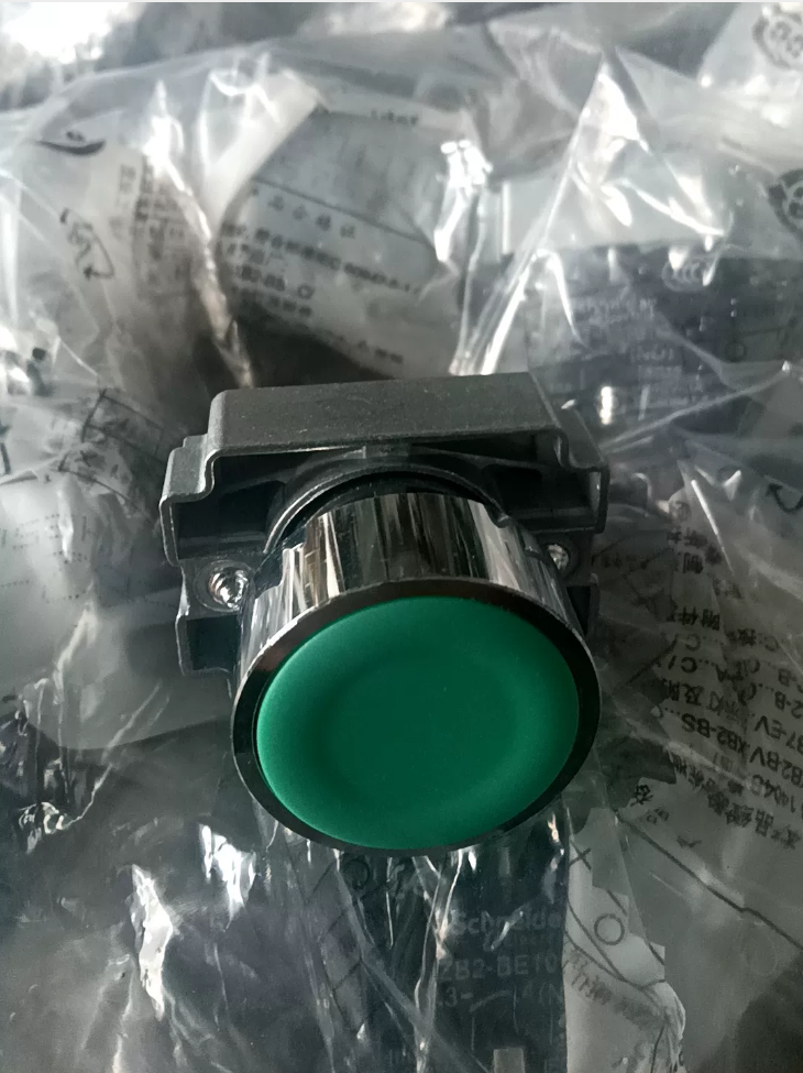

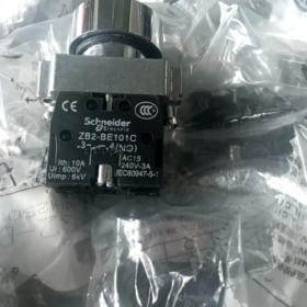
คำอธิบายโมเดล
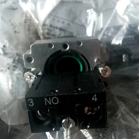
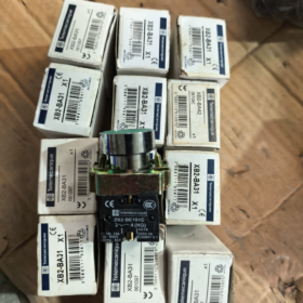
XB2-BA31C (รูปแบบการสั่งซื้อที่สมบูรณ์; คำต่อท้าย “ค” ไม่สามารถละเว้นได้)
XB2: ฮาร์โมนี่ XB2, 22 มม ชุดปุ่มกดโลหะ
ปริญญาตรี: ล้างหัว, ปุ่มกดสปริงกลับ
3: สีเขียว
1: 1 ปกติเปิดการติดต่อ (1เลขที่)
การแยกส่วนประกอบ: ZB2BA3C (หัวปุ่มกด) + ZB2BZ101C (1ไม่มีการบล็อกการติดต่อ)
- ข้อมูลจำเพาะทางเทคนิคหลัก
| รายการ | พารามิเตอร์ |
| เส้นผ่านศูนย์กลางของคัตเอาท์สำหรับติดตั้ง | คัตเอาท์แผงมาตรฐาน Φ22 มม |
| ประเภทการดำเนินงาน | ฤดูใบไม้ผลิกลับมา (ชั่วขณะ, รีบาวด์โดยอัตโนมัติเมื่อปล่อย) |
| สีของปุ่มกด | สีเขียว (ปุ่มกดสตาร์ทมาตรฐาน) |
| การกำหนดค่าการติดต่อ | 1เลขที่ (เปิดตามปกติ, ขั้ว 3-4) |
| วัสดุกรอบ | โลหะชุบโครเมียม, ทนต่อแรงกระแทก |
| ระดับการป้องกัน | IP65 (แผงด้านหน้า) |
| จัดอันดับกระแสความร้อน | 10 ก, แรงดันไฟฟ้าฉนวนที่กำหนด Ui = 600 วี |
| ความอดทนทางกล | ≥ 3 ล้านการดำเนินงาน |
| อุณหภูมิในการทำงาน | -25 ℃~ +55 ℃ |
| ประเภทสายไฟ | การเชื่อมต่อขั้วต่อสกรู |
- การใช้งานทั่วไป
ปุ่มกดสตาร์ทสำหรับตู้ควบคุมอุตสาหกรรม: สตาร์ทมอเตอร์, การกระตุ้นการทำงานของอุปกรณ์, วงจรควบคุมการเขย่าเบา ๆ.
การอ้างอิงที่ตรงกัน: ปุ่มกดหยุดสีแดง XB2-BA42C (1เอ็นซี)
- ปุ่มกดฟลัชทั่วไปของซีรีย์เดียวกัน
XB2-BA11C: สีขาว, 1เลขที่
XB2-BA21C: สีดำ, 1เลขที่
XB2-BA31C: สีเขียว, 1เลขที่ (รุ่นนี้)
XB2-BA41C: สีแดง, 1เลขที่; XB2-BA42C: สีแดง, 1เอ็นซี
XB2-BA51C: สีเหลือง, 1เลขที่
XB2-BA61C: สีฟ้า, 1เลขที่
- หมายเหตุการติดตั้ง
- ความหนาของแผงที่ใช้บังคับ: 1~6 มม
- แรงบิดในการขันที่แนะนำสำหรับน็อตยึด: 0.8 น.ม
- สำหรับการติดต่อเพิ่มเติม, สแต็ค ZB2-BE101 (เลขที่) / ZB2-BE102 (เอ็นซี) โมดูลการติดต่อ
- รุ่นนี้ไม่มีไฟแสดงสถานะในตัว; สำหรับปุ่มกดสตาร์ทสีเขียวเรืองแสง, เลือกซีรีส์ XB2BW33C
ขั้นตอนการติดตั้งเสร็จสมบูรณ์สำหรับ ชไนเดอร์ XB2-BA31C (XB2-BA31)
องค์ประกอบส่วนประกอบ: ZB2BA3C (หัวปุ่มกดแบบฟลัชสีเขียว) + ZB2BZ101C (1ไม่มีการบล็อกการติดต่อ)
เงื่อนไขเบื้องต้น & เครื่องมือ
- ข้อกำหนดของแผง
คัตเอาท์มาตรฐาน: Φ22 มม, คัตเอาท์ลบคมโดยไม่มีขอบคม
ความหนาของแผงที่ใช้บังคับ: 1~6 มม
ระยะห่างกึ่งกลางขั้นต่ำระหว่างปุ่มกดที่อยู่ติดกัน: ≥ 30 มม
- เครื่องมือที่จำเป็น
ไขควงปากแบน (พีเอช1), เครื่องปอกสายไฟ; แนะนำให้ใช้ไขควงทอร์ค
- ค่าแรงบิดมาตรฐานอย่างเป็นทางการ
น็อตยึดปุ่มกด: 0.8 น.ม (อย่าขันให้แน่นเกินไป)
สกรูขั้วต่อ: 0.5~0.8 นิวตันเมตร
- ข้อมูลจำเพาะของสายเคเบิล
แนะนำสายเคเบิลควบคุมทองแดงตีเกลียว 0.5~1.5 มม.², ความยาวปอก 7~10 มม
ลำดับการติดตั้งมาตรฐานทีละขั้นตอน
⚠️ก้าวแรกทุกงานไฟฟ้า: ตัดแหล่งจ่ายไฟหลักของตู้ควบคุม, ดำเนินการล็อค & แท็กเอาท์!
ขั้นตอน 1: สินค้าคงคลังชิ้นส่วน & การตรวจสอบด้วยสายตา
ตรวจสอบชุดที่สมบูรณ์หลังจากแกะกล่องออก:
- หัวปฏิบัติการปุ่มกดสีเขียว ZB2BA3C (พร้อมกับปะเก็นซีลเพื่อให้แน่ใจว่าการป้องกัน IP65)
- น็อตล็อคโลหะ
- บล็อกหน้าสัมผัส ZB2BZ101C (1เลขที่)
ตรวจสอบปะเก็นซีลว่ายังอยู่ในสภาพสมบูรณ์และสลักพลาสติกไม่มีรอยแตกร้าว.
ขั้นตอน 2: ใส่หัวปุ่มกดเข้าไปในแผงควบคุม (ติดตั้งจากด้านหน้าของแผง)
- ติดตั้งปะเก็นซีลเข้ากับไหล่ด้านหลังของหัวปุ่มกดอย่างถูกต้อง (ปะเก็นไม่สามารถละเว้นหรือบิดได้)
- ใส่หัวปุ่มกดเข้าไปในช่องเจาะ Φ22 มม. จากด้านนอก (ด้านหน้า) ด้านข้างของแผง
- ก้านเกลียวยื่นออกมาจากแผงด้านหลัง; ให้หัวปุ่มกดแนบสนิทกับพื้นผิวแผงโดยไม่เอียง
ขั้นตอน 3: ติดตั้งน็อตล็อคเพื่อยึดหัวปุ่มกด
- ขันน็อตล็อคโลหะเข้ากับก้านเกลียวจากด้านหลัง, แน่นด้วยมือจนกระทั่งแผงสัมผัส
- ขันให้แน่นด้วยเครื่องมือ, รักษาแรงบิดไว้ที่ 0.8 น.ม
✅เกณฑ์การยอมรับ: ปุ่มกดไม่มีการโยกเยก, กดเรียบไม่ติดขัด
❌อย่าออกแรงมากเกินไป! การขันแน่นเกินไปจะทำให้ปะเก็นซีลแตก, ทำให้เกิดการยึดปุ่มกดและทำให้การป้องกัน IP65 เป็นโมฆะ.
ขั้นตอน 4: บล็อกหน้าสัมผัสแบบ Snap-fit (จุดข้อผิดพลาดในการประกอบที่พบบ่อยที่สุด)
- สลักยางยืดสองตัวที่ด้านหน้าของบล็อกหน้าสัมผัสอยู่ในแนวเดียวกับช่องที่ด้านหลังของหัวปุ่มกด
- ดันบล็อกหน้าสัมผัสในแนวนอนและแนวตรง; สองเสียง “คลิก” เสียงยืนยันการมีส่วนร่วมของสลักทั้งสองอย่างเต็มรูปแบบ
❗ห้ามงัดทแยงมุมหรือออกแรงกดแรงๆ; สลักที่หักต้องเปลี่ยนบล็อกหน้าสัมผัส
✅วิธีกำจัด: งัดสลักทั้งสองด้านเบาๆ ด้วยไขควงปากแบน แล้วดึงบล็อกหน้าสัมผัสไปด้านหลัง
ขั้นตอน 5: การดำเนินการเดินสายไฟ (XB2-BA31, 1ไม่มีการติดต่อ)
เครื่องหมายขั้วต่อพิมพ์บนบล็อกหน้าสัมผัส:
เทอร์มินัล 3, 4 = เปิดตามปกติ (เลขที่): เปิดวงจรที่เหลือ, ปิดเมื่อกด
- ปอกฉนวนสายเคเบิล, ป้องกันเส้นทองแดงและเสี้ยนหลวม
- ใส่ตัวนำเข้าไปในรูขั้วต่อ; ตรวจสอบให้แน่ใจว่าฉนวนไม่ได้ถูกยึดไว้ใต้สกรู
- ขันสกรูขั้วต่อตามเข็มนาฬิกาให้แน่น (แรงบิด 0.5~0.8 นิวตันเมตร)
- การทดสอบแรงฉุดเล็กน้อยบนสายเคเบิลเพื่อยืนยันว่าไม่มีการหลวม; เกลียวทองแดงที่หลุดออกอาจทำให้เกิดความเสี่ยงในการลัดวงจรได้
ขั้นตอน 6: การทดสอบทางกลก่อนเปิดเครื่อง (ขั้นตอนบังคับ)
- กดปุ่มซ้ำๆ: การดำเนินงานราบรื่น, เด้งกลับอัตโนมัติทันทีหลังจากปล่อย, ไม่ติดหรือมีเสียงรบกวนผิดปกติ
- ตรวจสอบสลักบล็อกหน้าสัมผัสที่ล็อคจนสุดด้วยสายตา เพื่อหลีกเลี่ยงการหลุดออกภายใต้การสั่นสะเทือน
- ตรวจสอบปะเก็นซีลให้พอดีกับแผงอย่างสม่ำเสมอโดยไม่มีช่องว่าง (วิกฤตสำหรับฝุ่น & ต้านทานน้ำ)
ขั้นตอน 7: ทดสอบความต่อเนื่องก่อนการจ่ายไฟ
ใช้โหมดความต่อเนื่องของมัลติมิเตอร์เพื่อทดสอบขั้วต่อ 3 และ 4:
สถานะการพักผ่อน: วงจรเปิด (ความต้านทานไม่มีที่สิ้นสุด)
กดปุ่มค้างไว้: สื่อกระแสไฟฟ้า (ความต้านทานอยู่ใกล้ 0 โอ้)
ดำเนินการเปิดเครื่องต่อหลังจากผ่านการทดสอบแล้วเท่านั้น.
การอ้างอิงการเดินสายไฟทั่วไป (วงจรสตาร์ทมาตรฐาน)
แหล่งจ่ายไฟควบคุม → เทอร์มินัล 3
เทอร์มินัล 4 → คอยล์คอนแทคเตอร์ / อินพุตดิจิตอล PLC
กดปุ่ม → เทอร์มินัล 3-4 จัดการ, สัญญาณเริ่มต้นถูกทริกเกอร์
ข้อผิดพลาดในการติดตั้งทั่วไป & คำเตือน
- หายไป / ปะเก็นซีลบิดเบี้ยว → สูญเสียระดับ IP65; การซึมของฝุ่นและความชื้นทำให้เกิดการออกซิเดชั่นสัมผัสและค่าการนำไฟฟ้าต่ำ
- แรงบิดที่มากเกินไปบนน็อตยึด → กลไกภายในถูกบีบอัด, ปุ่มกดไม่สามารถเด้งกลับได้
- บล็อกหน้าสัมผัสบังคับในแนวทแยง → สลักพลาสติกแตกหัก; บล็อกหน้าสัมผัสอาจหลุดออกระหว่างการทำงานของอุปกรณ์
- สายไฟหลุดและเกลียวทองแดงหลวม → ความเสี่ยงของการลัดวงจรระหว่างขั้วต่อที่อยู่ติดกัน
- ช่องเจาะแผงที่มีขนาดใหญ่กว่า Φ22.2 มม. → ปุ่มกดโยกเยกและการปิดผนึกล้มเหลว
- อย่าติดตั้งคอนแทคบล็อกก่อน จากนั้นจึงกดปุ่มผ่านแผง! ลำดับที่ถูกต้อง: ยึดหัวปุ่มกดเข้ากับแผงก่อน, จากนั้นแนบบล็อกการติดต่อ
ขั้นตอนการถอดประกอบ (สำหรับการบำรุงรักษาแบบสัมผัส & ทดแทน)
ตัดไฟ → งัดสลักคอนแทคบล็อคสองอันด้วยไขควงปากแบน → ดึงคอนแทคบล็อคไปด้านหลัง;
เพื่อถอดปุ่มกดออกทั้งหมด: คลายเกลียวน็อตล็อคด้านหลัง, ดึงหัวปุ่มกดออกจากแผงด้านหน้า.
หลักการทำงานของชไนเดอร์ XB2-BA31C (XB2-BA31)
องค์ประกอบส่วนประกอบ: ZB2BA3C (หัวปุ่มกดกลับสปริงสีเขียว) + ZB2BZ101C (1ไม่มีการบล็อกการติดต่อ)
เป็นปุ่มกดชั่วขณะแบบกลไกโดยไม่มีไฟแสดงสถานะ.
- หลักการทำงานของเครื่องกล
- สถานะเริ่มต้น (ไม่ได้กด)
สปริงอัดในตัวดันส่วนหัวปฏิบัติการออกไปด้านนอกและรักษาตำแหน่งที่ขยายไว้. หน้าสัมผัสที่เคลื่อนที่ภายในถูกแยกออกจากหน้าสัมผัสที่อยู่กับที่.
- สถานะการดำเนินการ (กดปุ่มลง)
แรงภายนอกกดหัวปุ่มกดสีเขียว → ก้านกระทุ้งภายในเคลื่อนที่ไปข้างหลัง → ขับเคลื่อนสะพานหน้าสัมผัสแบบเคลื่อนย้ายได้ภายในบล็อกหน้าสัมผัสเพื่อเคลื่อนตัว
คอนแทคบริดจ์เชื่อมต่อคอนแทคเลนส์สองตัวที่อยู่กับที่พร้อมกัน, ขั้ว 3 และ 4 (เลขที่) ปิด.
- สถานะการปล่อย (กลับอัตโนมัติ)
เมื่อแรงกดดันจากภายนอกหายไป, สปริงในตัวจะเด้งกลับและรีเซ็ตก้านกระทุ้ง; สะพานสัมผัสหดกลับ, ผู้ติดต่อแยกจากกันอีกครั้ง, วงจรระหว่าง 3 และ 4 เปิด.
ลักษณะเฉพาะ: ประเภทชั่วขณะ (การดำเนินการเขย่าเบา ๆ), ไม่ล็อค; สื่อกระแสไฟฟ้าเฉพาะในขณะที่ถูกกด.
- หลักการไฟฟ้า (XB2-BA31: 1ไม่เปิดตามปกติ)
การทำเครื่องหมายเทอร์มินัลบนบล็อกหน้าสัมผัส: 3, 4 = เปิดตามปกติ (เลขที่)
สถานะคงที่: วงจรเปิดระหว่าง 3 และ 4 (ความต้านทานไม่มีที่สิ้นสุด)
ปุ่มกด: วงจรปิดระหว่าง 3 และ 4
เมื่อได้รับการปล่อยตัว: วงจรคืนค่าสถานะเปิดทันที
หน้าสัมผัสคือหน้าสัมผัสแบบแห้งเชิงกลแบบพาสซีฟ:
ไม่มีแหล่งจ่ายไฟในตัว; เพียงเปิด/ปิดวงจรควบคุมภายนอกเท่านั้น. ใช้งานได้กับลูปควบคุม AC/DC แรงดันต่ำ (คอยล์คอนแทค, อินพุต PLC DI, วงจรรีเลย์).
- การแยกย่อยโครงสร้างภายในโดยย่อ
- ที่อยู่อาศัยปุ่มกด + สปริงกลับ
- ก้านกระทุ้งส่งกำลัง (ส่งแรงกด)
- ติดต่อบล็อค: แก้ไขผู้ติดต่อที่อยู่กับที่ + สะพานหน้าสัมผัสแบบเคลื่อนย้ายได้
- ขั้วต่อสายไฟแบบสกรู
ลำดับการส่งแรง:
การกดแบบแมนนวล → หัวปุ่มกด → ก้านกระทุ้งบีบอัดสปริง → การเคลื่อนตัวของสะพานหน้าสัมผัส → หน้าสัมผัสปิด
ปุ่มปลดล็อค → สปริงขยายและรีเซ็ต → การถอยของคอนแทคบริดจ์ → ผู้ติดต่อเปิด
- ลักษณะสำคัญ
- ไม่มีไฟแสดงสถานะในตัว, ไม่จำเป็นต้องใช้แหล่งจ่ายไฟแสงสว่าง; แตกต่างจากรุ่นส่องสว่าง XB2BW33C.
- การสลับหน้าสัมผัสทางกลทางกายภาพล้วนๆ โดยไม่มีส่วนประกอบอิเล็กทรอนิกส์, ประสิทธิภาพการป้องกันการแทรกแซงที่แข็งแกร่ง.
- การป้องกันระดับ IP65 อาศัยปะเก็นซีลด้านหน้าเพื่อป้องกันไอน้ำและฝุ่นเข้าไปในช่องสัมผัส.
- ตรรกะแอปพลิเคชันทั่วไป (ตัวอย่างวงจรสตาร์ทมอเตอร์)
ควบคุมสด L → Terminal 3
เทอร์มินัล 4 → คอนแทคเตอร์ KM คอยล์ → Neutral N
เมื่อกด XB2-BA31C → คอยล์ KM จะรวมพลังงาน, คอนแทคเตอร์ดึงเข้า;
วงจรปุ่มกดจะเปิดขึ้นเมื่อปล่อย, การทำงานต่อเนื่องบำรุงรักษาโดยการล็อคตัวเองผ่านหน้าสัมผัสเสริม NO ของคอนแทค.
ความเข้าใจผิดที่พบบ่อย
❌ไม่ใช่ปุ่มกดล็อค: วงจรเปิดหลังปล่อย, ไม่สามารถรักษาสถานะการนำได้
❌ ไม่เหมาะเป็นลิมิตสวิตช์ภายใต้การบีบอัดอย่างต่อเนื่อง; เร่งความเมื่อยล้าของสปริง
❌ หน้าสัมผัสทำหน้าที่เฉพาะวงจรควบคุมเท่านั้น, ไม่สามารถขับเคลื่อนโหลดกำลังสูงได้โดยตรง





NH42-63-318x560.png "สวิตช์ถ่ายโอนอัตโนมัติชนิด CHINT PC (เอทีเอส)NH42-63/4SZ")



