 المقاولين,قاطع الدائرة,الاستشعار,التشفير,بلك,محول

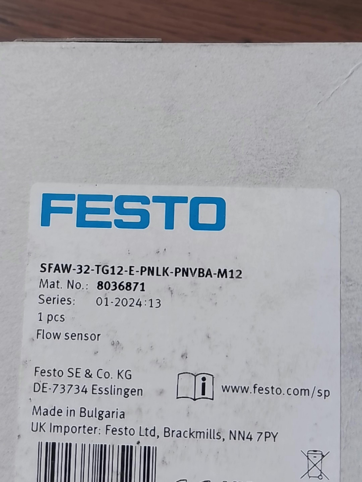

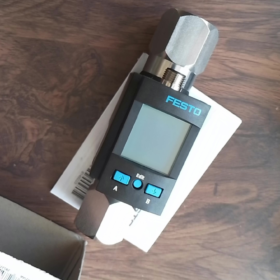
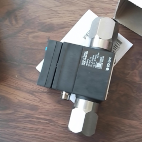
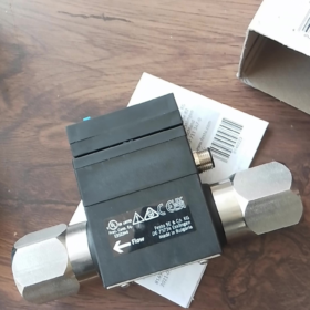
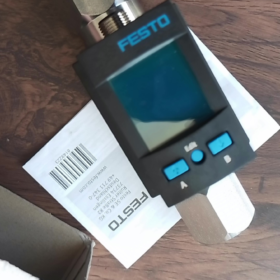
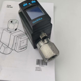
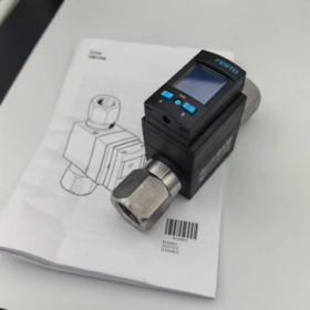
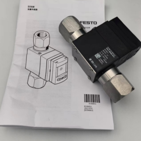
رقم الجزء: 8036871|Vortex Liquid مستشعر التدفق (without integrated temperature measurement)
> Distinction note: Model with temperature measurement: SFAW-32T-TG12-E-PNLK-PNVBA-M12 (8036872) – extra letter T in the model code.
- انهيار رمز النموذج
| الجزء النموذجي | تعريف |
| SFAW | Liquid flow sensor series (vortex measuring principle) |
| 32 | Full scale range: 32 L/min; measuring lower limit: 1.8 L/min |
| No suffix T | No built-in temperature probe (32T = equipped with PT1000 temperature sensor) |
| TG12 | Process connection: G1/2 internal thread (DN15) |
| ه | Outlet process connection identical to inlet (G1/2 internal thread) |
| PNLK | قناة 1: PNP/NPN switchable + IO-Link V1.1 |
| PNVBA | قناة 2: PNP/NPN switchable digital output OR analogue output (4-20 مللي أمبير / 0-10 فولت / 1–5V) |
| م12 | Electrical connector: M12×1 A-coded 5-pin straight connector |
- المواصفات الفنية الرئيسية
Fluid Parameters
Measuring principle: Vortex shedding
نطاق القياس: 1.8 … 32 L/min, unidirectional flow P1→P2
ضغط التشغيل: 0~12 bar; الأعلى. 12 bar @ 40℃, الأعلى. 6 bar @ 90℃
Burst test pressure: 40 حاجِز
Suitable media: Water, neutral low-viscosity liquids; kinematic viscosity ≤1.8 mm²/s
Medium temperature: 0 … +90 درجه مئوية
درجة الحرارة المحيطة: 0 … +50 درجه مئوية
المواصفات الكهربائية
مزود الطاقة: العاصمة 18 … 30 V, حماية قطبية عكسية
رابط الإدخال والإخراج: V1.1, كوم2 (38.4kBaud), SIO mode supported, minimum cycle time 5ms
Output configuration:
- خارج1: PNP/NPN configurable, switch point/window comparison, NO/NC programmable
- خارج2: Selectable digital output or analogue output (4-20 مللي أمبير / 0-10 فولت / 1–5V)
الأعلى. load per digital output: 100 أماه
فئة الحماية: IP65
Wetted materials: PA6T/6I; السكن: reinforced PA
وزن: تقريبا. 400 ز
الشهادات: م, cULus, UKCA, بنفايات, LABS-compliant (suitable for oil-free systems)
ثالثا. M12 5-Pin Pin Assignment (A-coded)
- دبوس1: +24في العاصمة (Power Positive)
- دبوس2: خارج2 (رقمي / Analogue Output)
- دبوس3: 0V GND (القوة سلبية)
- دبوس4: خارج1 / IO-Link communication line
- دبوس5: Not assigned
> Under IO-Link mode, Pin4 serves as main communication channel; under SIO mode, Pin4 acts as digital switching output.
- التطبيقات النموذجية
Pure water cooling circuits, machine tool cooling systems, معدات الغسيل, auxiliary hydraulic cooling, neutral fluid monitoring in food industry, flow totalisation measurement.
- اختيار & إرشادات الاستبدال
- If medium temperature measurement is required → Upgrade to 8036872 SFAW-32T-TG12-E-PNLK-PNVBA-M12
- For NPT/Rc thread connections, modify the TGxx segment in model code
- If only two digital outputs are needed without analogue signal, select simplified output variants to reduce cost
- Same housing higher flow variant: SFAW-100 (5~100 L/min)
- Important Risk Warnings
Reverse fluid flow is strictly prohibited, flow direction must be P1→P2; reverse flow will damage the measuring element
Media must be free of solid particles; filter installation upstream is recommended
Maintain straight pipe sections before and after sensor for measurement accuracy (upstream ≥5×DN, downstream ≥3×DN)
Digital output and analogue output cannot be activated simultaneously on OUT2; mode selection must be set via menu
حزب SFAW-32-TG12-E-PNLK-PNVBA-M12 (رقم الجزء. 8036871) أبعاد التثبيت
> SFAW-32 (without temperature) and SFAW-32T (with temperature) share identical outer dimensions; TG12 = G1/2 internal thread version
- Key Overall Dimensions (وحدة: مم)
- Centre-to-centre distance of process ports (pipe mounting length)
ل = 73.2 مم (P1 inlet G1/2 internal thread ↔ P2 outlet G1/2 internal thread)
- Valve body width (excluding display): 50 مم
- Maximum overall height (valve bottom to top of display): 92 مم
- Maximum overall depth (rear valve surface to display buttons): 61.2 مم
- Process thread specification: Both ends G1/2 internal thread (TG12)
- Bracket Mounting Hole Layout (for optional mounting bracket)
| المعلمة | البعد(مم) | ملاحظات |
| Horizontal hole spacing B1 | 50 | Centre distance between two horizontal mounting holes |
| Vertical hole spacing B2 | 35 | Centre distance between two vertical mounting holes |
| Mounting hole diameter D1 | Ø5.2 | Suitable for M5 screws |
| Inner clearance B3 | 20 | |
| Outer edge margin B4 | 18 |
> Mounting holes arranged in rectangle: 50 × 35 مم, fixed with 4 × M5 screws.
ثالثا. Clearance Requirement for Electrical Connection
M12×1 A-coded 5-pin straight connector extends horizontally outwards from the side of the display
Recommended minimum clearance ≥35 mm on connector side for easy plug mating and removal
Display supports ±90° rotation for flexible readout orientation in cabinet layout
- Mandatory Straight Pipe Requirements for Accuracy
المنبع (inlet side) straight pipe: ≥5×DN15 ≈75 mm
Downstream (outlet side) straight pipe: ≥3×DN15 ≈45 mm
Do not install immediately adjacent to elbows, tees, ball valves or reducers;
Flow direction P1→P2 only; reverse installation forbidden.
- وزن
الوزن الصافي: 400 ز
- Layout Design Notes
- Process ports are G1/2 internal thread; reserve wrench clearance when fitting male thread adapters
- The display is rotatable; reserve minimum 8 mm clearance on all sides if cabinet cutout is planned
- Max medium temperature reaches 90℃; arrange proper heat resistance for surrounding cables and seals





NH42-63-318x560.png "مفاتيح النقل التلقائي من نوع الكمبيوتر الشخصي CHINT (المنشطات الأمفيتامينية)NH42-63/4SZ")



