 المقاولين,قاطع الدائرة,العاكس للطاقة الشمسية,عداد كهرباء,البطاريات الشمسية

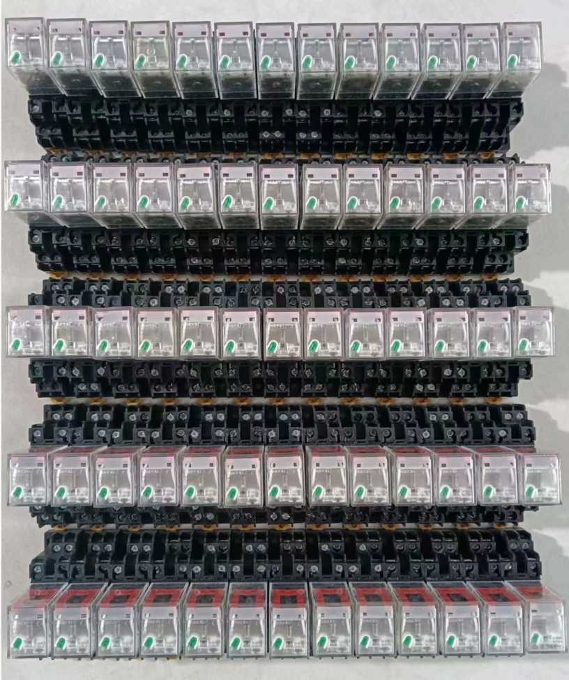

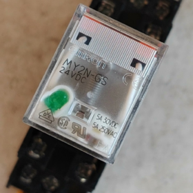
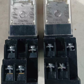
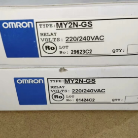
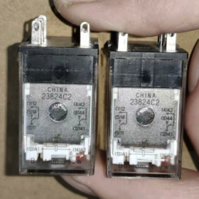
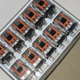
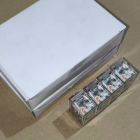
ال اومرون MY2N-GS AC220V is a 2-pole double-throw (دي بي دي تي) plug-in miniature intermediate relay from OMRON MY-GS series. It is the official upgraded replacement for the classic legacy model MY2N-J. Standard configurations include an LED operation indicator, mechanical status indicator and manual test locking lever. Adopting silver alloy contacts, ويتميز بموثوقية عالية, long service life and convenient wiring. Mainly used for PLC output signal amplification, load switching and circuit logic conversion, it is a universal fundamental component for industrial automation control cabinets.
- انهيار رمز النموذج
Full standard model: MY2N-GS AC220/240V
MY: سلسلة المنتجات, general-purpose miniature power intermediate relay
2: Number of contact sets, 2 مجموعات من الاتصالات التحول (دي بي دي تي, 2 مفتوح عادة + 2 مغلق عادة)
ن: Standard plug-in terminals with built-in operation indicator
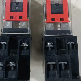
GS: Next-generation series (Generation Standard). It replaces the original MY2N-J series, is equipped with an additional locking lever, and delivers optimized contact durability and electrical performance.
AC220/240V: Rated coil voltage, AC 220~240V, compatible with 50/60Hz power supply.
ملاحظات تكميلية
Most products available on the market are fitted with a locking lever by default (suffix -R), supporting manual testing and contact locking.
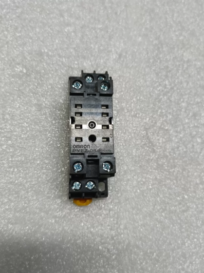
Matched standard 8-pin socket: Screw terminal type PYF08A, push-in terminal type PYF08A-PU.
- المواصفات الفنية الرئيسية
| فئة | تحديد |
| تكوين الاتصال | 2 مجموعات من الاتصالات التحول (دي بي دي تي, 2لا + 2NC) |
| Rated Contact Current | 5أ (AC250V resistive load); 5أ (DC30V resistive load) |
| مواد الاتصال | سبائك الفضة (AgSnO₂) |
| Rated Coil Voltage | AC 220~240V, 50/60هرتز |
| استهلاك طاقة الملف | تقريبا. 1.2~1.5 VA |
| Operate Time | ≥ 20 آنسة |
| وقت الإصدار | ≥ 20 آنسة |
| الحياة الميكانيكية | ≥ 50 مليون عملية |
| الحياة الكهربائية | ≥ 100,000 العمليات (under rated resistive load) |
| Dielectric Withstand Voltage | 2kV AC / 1دقيقة (between coil and contacts) |
| إشارة الحالة | Red LED indicator (lights up when energized) + Mechanical indicator lever |
| نوع التركيب | نوع البرنامج المساعد, used with matched standard socket |
| Number of Pins | 8 دبابيس |
| درجة حرارة التشغيل المحيطة | -40درجه مئوية ~ +70 درجه مئوية (No condensation) |
| حماية الدخول | IP40 (Relay body) |
| الشهادات | م, أول, وكالة الفضاء الكندية, VDE, CQC |
- Full Model List of the Same Series
4.1 Classified by Contact Sets
| Contact Sets | Pin Count | النموذج القياسي | Model with Locking Lever | Rated Contact Current |
| 2 اتصالات التحول (2لا + 2NC) | 8 دبابيس | MY2N-GS | MY2N-GS-R | 5أ |
| 4 اتصالات التحول (4لا + 4NC) | 14 دبابيس | MY4N-GS | MY4N-GS-R | 5أ |
4.2 Common Coil Voltage Ratings
The entire series supports the following standard voltages, distinguished only by voltage suffix:
العاصمة: DC12V, تيار مستمر 24 فولت, DC48V
تكييف: تيار متردد 24 فولت, AC110/120V, AC200/220V, AC220/240V
- Pin Assignment & تعليمات الأسلاك
5.1 Pin Definition (Top view from the wiring side of the socket)
| رقم الدبوس. | وظيفة | وصف |
| 13 (أ1) | One end of coil | Connect to AC220V live wire |
| 14 (A2) | The other end of coil | Connect to AC220V neutral wire |
| 9 | محطة مشتركة 1 (كوم1) | Common pin for the 1st contact set |
| 1 | مغلق عادة 1 (NC1) | Conducts with Pin 9 when coil is de-energized |
| 5 | مفتوح عادة 1 (NO1) | Conducts with Pin 9 when coil is energized |
| 12 | محطة مشتركة 2 (كوم2) | Common pin for the 2nd contact set |
| 4 | مغلق عادة 2 (NC2) | Conducts with Pin 12 when coil is de-energized |
| 8 | مفتوح عادة 2 (NO2) | Conducts with Pin 12 when coil is energized |
5.2 احتياطات الأسلاك
- The AC coil has no polarity requirement. A1 and A2 can be connected to live wire and neutral wire arbitrarily.
- للأحمال الحثية (المقاولين, صمامات الملف اللولبي), it is recommended to connect a surge suppressor (RC snubber circuit) in parallel to extend contact service life.
- Do not operate beyond the rated current. Use contactors for secondary switching of high-power loads.
- The locking lever can manually close the contacts, which is applied to power-off commissioning and circuit inspection.
- التطبيقات النموذجية
Amplify PLC output signals to drive loads such as solenoid valves, contactors and indicator lights
Circuit logic conversion, level matching and signal isolation inside control cabinets
Start-stop control, signal relay and circuit expansion for automated equipment
Secondary circuit control and protection signal transmission in power distribution systems
- General Troubleshooting Matrix
| ظاهرة الخلل | السبب الجذري | حلول خطوة بخطوة |
| Relay fails to operate and indicator stays off after power-on | 1. Abnormal supply voltage / Broken wiring | 1. Measure voltage between A1 and A2 to confirm normal AC220V supply |
| 2. Burned-out open coil | 2. اختبار مقاومة الملف; replace the relay if an open circuit is detected | |
| 3. Poor contact with socket | 3. Re-insert the relay and clean socket pins | |
| Indicator lights up but contacts have no output | 1. Welded or oxidized contacts with poor conduction | 1. Test contact continuity; replace the relay if contacts are damaged |
| 2. Broken wiring on load side | 2. Check wiring and integrity of the load circuit | |
| 3. Damaged contacts due to overload | 3. Verify load current; select a higher-rated model for overload conditions | |
| Contacts fail to release and stick together after power-off | 1. Contact welding caused by electric arc under heavy current | 1. Replace the relay and install surge suppression components |
| 2. Mechanical jam or failed return spring | 2. Inspect internal mechanism; replace the whole relay if mechanical jam occurs | |
| Abnormal buzzing noise during operation | 1. Incomplete armature attraction due to low voltage | 1. Adjust supply voltage to the rated range |
| 2. Oil or dust on core surface | 2. استبدل التتابع; do not disassemble the core manually | |
| Excessive heating or burnout of coil | 1. Overvoltage power supply | 1. Ensure supply voltage complies with rated value; overvoltage operation is prohibited |
| 2. Long-term high-frequency switching | 2. Reduce switching frequency or adopt solid state relays |
- Reference of Alternative Models
Original brand legacy replacement: MY2N-J AC220V (Fully pin-compatible, without locking lever)
البدائل المحلية: Chint NJX-13FW/2Z AC220V, Delixi CDZ9-52P AC220V
Imported equivalents: شنايدر RXM2LB2P7, ABB CR-MX230AC2L, Phoenix Contact REL-MR-230AC/21
Troubleshooting Matrix for OMRON MY2N-GS AC220V 5A Relay
This model features 2 مجموعات من الاتصالات التحول, 8-pin plug-in structure, LED operation indicator and locking lever. Below is the troubleshooting guide sorted by on-site inspection sequence (from simple to complex), covering faults caused by electrical, mechanical and installation issues.
| ظاهرة الخلل | السبب الجذري | حلول خطوة بخطوة |
| No operation and red LED indicator off after power-on | 1. Fault in external power circuit: No voltage, الأسلاك فضفاضة, broken live/neutral wire | 1. Measure AC voltage between socket Pin 13(أ1) and Pin 14(A2). Confirm voltage within AC220V±10%. Check upstream switches and terminals if no voltage is detected. |
| 2. اتصال مقبس ضعيف: Oxidized pins or loose connection between relay and socket | 2. Cut off power, pull out the relay, clean oxide on pins and socket terminals, then reinsert firmly. | |
| 3. Burned-out open coil: Overvoltage breakdown, insulation aging or surge impact | 3. قياس مقاومة الملف. The normal resistance is approx. 12~15kΩ at 25℃. Replace the relay if open circuit or abnormal resistance occurs. | |
| 4. Locking lever stuck at release position (for -R version) | 4. Reset the top locking lever to normal position to eliminate mechanical jam. | |
| LED lights up but contacts have no output | 1. Wrong wiring for contact circuit: Mixed connection of common, NO and NC terminals | 1. Verify pin definition: COM terminals are Pin 9 and Pin 12; NO terminals are Pin 5 and Pin 8. Ensure no wrong connection to NC pins. |
| 2. Broken load circuit: No power for load or loose terminals | 2. Press the locking lever to manually close contacts and test continuity. If still open, inspect power and wiring on load side. | |
| 3. Burned or oxidized contacts caused by long-term overload and electric arc | 3. Replace the relay if contacts remain open due to burnout or oxidation after manual closing. | |
| 4. Internal mechanism jam: Coil pulls in normally but linkage fails to drive contacts | 4. Replace the relay if mechanical jam is found during manual operation. | |
| Contacts stay closed and cannot release after power-off | 1. الاتصال باللحام: Caused by overload, short circuit or electric arc without surge suppression for inductive loads | 1. Cut off power and confirm no voltage on coil. Reset locking lever and check if contacts open. |
| 2. Failed return spring: Elasticity attenuation due to frequent switching and high temperature | 2. Replace the relay immediately if contacts are still closed after reset. Welded contacts cannot be repaired for reuse. | |
| 3. Foreign matter jam: Dust or iron chips stuck inside armature or contact mechanism | 3. Ensure load current does not exceed 5A. Install RC surge suppressor for inductive loads. | |
| 4. Accidental lock of locking lever after manual test | 4. Clean surrounding dust and iron chips; replace the relay if mechanical jam cannot be fixed. | |
| Abnormal buzzing noise during operation | 1. Low supply voltage leads to incomplete core attraction and armature vibration | 1. Measure coil voltage and keep it within AC220V±10%. Check voltage drop in power circuit if voltage is low. |
| 2. Oil, dust or rust on core surface resulting in excessive magnetic gap | 2. Reinsert the relay fully and tighten fixing screws of socket and rail. | |
| 3. Broken short-circuit ring on core (unique fault of AC coil) | 3. Replace the relay if noise persists after cleaning core surface (damaged short-circuit ring or worn core). | |
| 4. Loose fit between relay, socket and DIN rail causing resonance | 4. Adjust mounting position to eliminate resonance gap. | |
| Excessive heating or black burnout of coil | 1. Severe overvoltage exceeding upper limit AC240V leading to coil overload | 1. Monitor supply voltage strictly; long-term overvoltage operation is forbidden. |
| 2. Excessively high switching frequency causes cumulative overheating beyond Class B insulation limit | 2. Limit switching frequency ≤ 20 times per minute. Use solid state relay for high-frequency working conditions. | |
| 3. Poor heat dissipation under high ambient temperature accelerates insulation aging | 3. Improve heat dissipation inside cabinet. Keep away from heat-generating components such as inverters and contactors. Ambient temperature shall not exceed 70℃. | |
| 4. Insulation breakdown caused by overvoltage and surge | 4. Connect RC surge suppressor in parallel with coil to suppress transient overvoltage during power-off. | |
| اتصال ضعيف, intermittent signal | 1. Oxidation and dust on contact surface leading to high contact resistance | 1. Cut off power, pull out the relay, clean oxide on contacts and pins, then insert tightly. |
| 2. Too low load current cannot break through oxide layer (low-level signal circuit) | 2. Use gold-plated contact relay or properly increase circuit current for low-level signal applications. | |
| 3. Fatigue or oxidation of socket pins causing loose connection | 3. Replace matched PYF08A socket if pins lose elasticity or are severely oxidized. | |
| 4. Incomplete insertion of relay leading to mechanical intermittent contact | 4. Replace with a new relay if intermittent fault occurs frequently to prevent repeated oxidation. | |
| Abnormal brightness or flickering of indicator | 1. Unstable power supply with large voltage fluctuation | 1. Measure coil voltage and confirm stable power supply without severe fluctuation. |
| 2. Poor socket contact leading to intermittent coil power supply | 2. Reinsert the relay and clean pins to eliminate loose contact. | |
| 3. Aging and failure of current-limiting resistor for indicator | 3. Measure coil resistance if indicator malfunctions under stable voltage. Replace the relay immediately if inter-turn short circuit (مقاومة منخفضة) is detected. | |
| 4. Coil inter-turn short circuit causing abnormal voltage division | 4. Temporary use is allowed if only indicator fails while contacts work normally. Batch replacement is recommended. |
Supplementary Troubleshooting Notes
- Inspection Priority: Follow the sequence: External power supply → Socket contact → Relay body. 80% of faults are caused by wiring and socket problems. Prioritize these checks to avoid unnecessary replacement.
- Safety Regulations: Comply with electrical safety standards during live tests. Cut off power before inspecting contacts and coils to prevent electric shock and short circuit.
- Service Life Reference: The rated electrical life is 100,000 operations under resistive load. The service life will decrease by more than 50% للأحمال الحثية. Regular replacement is recommended when the service limit is reached.


")


NH42-63-318x560.png "مفاتيح النقل التلقائي من نوع الكمبيوتر الشخصي CHINT (المنشطات الأمفيتامينية)NH42-63/4SZ")


