 المقاولين,قاطع الدائرة,الاستشعار,التشفير,بلك,محول

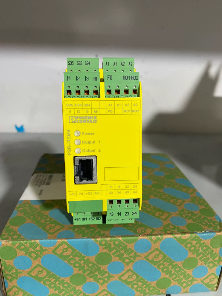

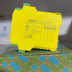
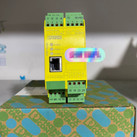
Phoenix Contact Order No. 2981541
- المعلومات الأساسية
ماركة: اتصال فينيكس (the spelling “phonex” mentioned is a typo)
النموذج الكامل: PSR-SPP-24DC/RSM4/4X1
Material Order Number: 2981541
تحديد موضع المنتج: Dual-channel speed monitoring safety module, specially designed for motor overspeed/zero-speed monitoring, belonging to the PSR-TRISAFE safety مسلسل
- تعريف رمز النموذج
| مقطع الكود | تعريف |
| بي إس آر | Phoenix Safety Relay, Phoenix Contact safety relay series |
| SPP | TRISAFE programmable safety monitoring module |
| 24العاصمة | Operating supply voltage: تيار مستمر 24 فولت |
| RSM4 | Rotation Speed Monitor, speed monitoring with Ethernet port software configuration |
| 4X1 | 4 normally-open safety output contacts |
| 2981541 | Unique factory order code |
- Core Safety Certification Levels (المعلمات الرئيسية)
- في ايزو 13849: بل ه / فئة 4 (Highest machinery safety level)
- اللجنة الانتخابية المستقلة 61508 / اللجنة الانتخابية المستقلة 62061: سيل 3
- إيقاف الفئة: فئة 0 safety cut-off per EN 60204-1
- اتصالات: Force-guided safety contacts compliant with IEC/EN 61810-3, mechanical service life > 50 مليون عملية
- Electrical and Mechanical Specifications
4.1 مدخلات مصدر الطاقة
الجهد المقنن: تيار مستمر 24 فولت, allowable range: 20.4~26.4V
تصنيف المدخلات الحالية: 100أماه
4.2 Speed Measurement Input (Dual-channel IN1/IN2)
Supported sensors: Incremental encoders, مفاتيح القرب, Hall effect sensors
الأعلى. تردد الإدخال: 2كيلو هرتز
Typical Response Time: 15آنسة; وقت الإصدار: 12آنسة; Recovery Delay: 1ق
4.3 مخرجات السلامة
4 independent normally-open safety contacts (4PST-NO)
تقييم الاتصال: 250الخامس و / 5أ
4.4 الأبعاد الميكانيكية
عرض: 45مم, ارتفاع: 112مم, عمق: 114.5مم
تصاعد: سكة DIN القياسية مقاس 35 مم
الأسلاك: Plug-in spring-cage terminals
فئة الحماية: IP20 (for cabinet internal installation only)
درجة حرارة التشغيل: -20درجه مئوية ~ +55 درجه مئوية; درجة حرارة التخزين: -40درجه مئوية ~ +70 درجه مئوية
4.5 Configuration Interface
Built-in front-side RJ45 Ethernet port. The supporting software PSR-RSM4 enables online parameter setting via PC, including overspeed threshold, zero-speed threshold, وقت التأخير, dual-channel verification logic and fault diagnosis parameters.
- سيناريوهات التطبيق النموذجية
- Lifting equipment and winches: Prevent drum runaway caused by overspeed
- Fans and centrifuges: Overspeed protection and emergency stop
- Conveyors and roller motors: Safety door unlocking after zero-speed confirmation
- Machine tool spindles and rotating tooling: Dual-channel redundant speed safety monitoring
Advantags: Dual-channel redundant detection maintains safe cut-off even if one channel fails, complying with machinery safety regulations for equipment.
- Function Overview
- Dual-channel redundant speed measurement: Compare signals from two encoders to avoid failure risks from open/short circuit of a single channel
- Two operating modes:
Overspeed protection: Immediately cut off safety outputs when rotation speed exceeds preset threshold
Zero-speed monitoring: Judge stationary state when speed drops below threshold and allow safety door unlocking
- Fault diagnosis: Read fault codes via Ethernet port (دائرة مفتوحة, ماس كهربائى, speed out of limit, channel deviation)
- Safety feedback loop: Supports monitoring of external contactor auxiliary contacts to prevent contact welding failure
- Supporting Products & نماذج بديلة
- برامج التكوين: PSR-RSM4 (free download on Phoenix Contact official website)
- Distinction of alternatives within the same series:
2981541: Programmable speed monitoring with Ethernet port, 4 normally-open contacts
PSR-SPP-24DC/ESD: General safety relay for emergency stop / باب السلامة, without speed monitoring function
- HS Customs Code: 85364900 (Electromagnetic safety relays)
- ملاحظات المشتريات
EAN Barcode: 4017918996833
EMC Class: الفئة أ (For industrial environments only, not applicable to civil weak-current environments)
التعبئة والتغليف القياسية: Single unit per box, 12-month original manufacturer warranty
Complete Working Principle of Phoenix Contact PSR-SPP-24DC/RSM4/4X1 (2981541) تتابع سلامة مراقبة السرعة
This unit is a TRISAFE programmable dual-channel speed safety module. Its core design adopts a triple safety architecture: Fail-Safe principle + dual-channel redundant speed detection + force-guided safety outputs. It integrates programmable overspeed/zero-speed logic, full-circuit self-test and contactor feedback monitoring, achieving the highest safety rating of PL e / القطة 4 / سيل 3.
- Hierarchical Overall Hardware Architecture (Input to Output)
The unit consists of 4 independent isolated modules:
- DC24V Power Supply Unit (Terminals A1/A2): Power supply for the whole device and internal self-test circuit
- Dual-channel Speed Input Unit (في1, IN2): Two fully independent circuits for collecting rotation pulse signals
- Dual-core Safety Logic Processing Unit (with RJ45 configuration port): Hardware comparison of dual signals, threshold judgment and fault diagnosis
- 4-channel Force-guided Safety Relay Output Unit: Divided into two isolated safety loops (emergency stop cut-off + safety door unlock enable), equipped with external contactor feedback monitoring circuit
- خطوة 1: Working Principle of Dual-channel Speed Signal Acquisition (Core Redundant Detection)
2.1 Supported Sensor Types
Dual-channel incremental encoders (A/B phase quadrature pulses)
Two independent NPN/PNP proximity switches, Hall effect speed probes
IN1 and IN2 inputs feature complete electrical isolation and separate sampling circuits to realize dual-channel redundant verification, eliminating safety hazards caused by open circuits, short circuits or single probe failure.
2.2 Calculation Logic: Convert Pulses to Rotation Speed
Sensors output frequency pulses synchronously with motor shaft rotation (الأعلى. 2كيلو هرتز). Internal hardware counters capture pulse frequencies of both channels in real time and convert them to actual rotation speed via the formula:
2.3 Dual-channel Consistency Verification (Core Safety Feature)
The logic unit continuously compares converted speed values from IN1 and IN2:
If speed deviation between two channels is within software-set tolerance → Signals are deemed valid
If single channel open/short circuit, pulse loss or excessive channel deviation is detected → Speed circuit fault is triggered instantly, all safety outputs are cut off and fault state latched
> Safety implication: Single-channel faults cannot mask overspeed risks, meeting machinery safety redundancy requirements.
- خطوة 2: Programmable Safety Logic Judgment (Dual Modes: السرعة الزائدة / السرعة صفر)
Two groups of thresholds are preset via connecting a PC with PSR-RSM4 software over RJ45 port. The module compares real-time measured speed against thresholds and operates under two modes:
وضع 1: Overspeed Protection (For winches, أجهزة الطرد المركزي, spindle runaway prevention)
- Measured speed > Software-set overspeed threshold
- Internal dual-core safety circuitry immediately de-energizes coils of two groups of safety output relays
- الجميع 4 normally-open safety contacts are forced open within 15ms to cut off main motor contactor and servo enable loops
- Fault state latches; power cycle reset or external reset terminal must be used to clear fault before resuming operation
وضع 2: Zero-speed Monitoring (باب الأمان / maintenance door interlock)
- Measured speed < Software-set stationary zero-speed threshold and held for preset delay duration
- The second group of safety contacts remains closed to output a safety door unlock enable signal, allowing access to machine guard doors
- Once minor shaft rotation occurs and speed exceeds zero-speed threshold, enable contacts open within 12ms to lock safety doors and prevent personnel entanglement with rotating components
Additional Logic: External Contactor Feedback Monitoring (EDM Loop)
Auxiliary normally-closed contacts of the main contactor are wired to dedicated terminals for continuous monitoring:
Normal closed safety outputs → Contactor energized, feedback contacts open, logic confirms normal status
Welded output contacts or stuck contactor that cannot open → Abnormal feedback loop detected; module latches in safety cut-off state to eliminate runaway risks from contact failure
- خطوة 3: Execution Principle of Force-guided Safety Outputs (اللجنة الانتخابية المستقلة 61810-3)
The module integrates 4 independent force-guided safety relays, split into two isolated safety loops:
- المحطات 13-14, 23-24: Overspeed emergency stop cut-off loop (controls main power contactor)
- المحطات 33-34, 43-44: Zero-speed safety door enable loop (guard door unlock interlock)
Safety Mechanism of Force-guided Contacts (Distinguished from Ordinary Relays)
A mechanical linkage binds normally-open and normally-closed contacts of the same relay:
If normally-open contacts are welded closed by electric arcs and fail to open, the mechanical linkage mechanically restrains corresponding normally-closed contacts from closing
Auxiliary alarm contacts MO1/MO2 switch state upon output faults to transmit fault codes to PLC
This design guarantees that any single-point component failure forces outputs to the open (آمن) ولاية, complying with the Fail-Safe principle.
- Principle of Full-unit Periodic Self-test & تشخيص الخطأ
Continuous hardware self-test runs during power-up and full operation, covering the entire signal chain:
- Input Loop Self-test: Detect IN1/IN2 short to 24V, short to 0V and open circuit
- Internal Processing Unit Self-test: Mutual verification between dual cores; immediate shutdown if one chip malfunctions
- Output Relay Self-test: Detect coil open circuit and contact welding (coordinated with EDM feedback)
- Communication Self-test: Fault codes readable via RJ45 port: overspeed trigger, zero-speed loss, channel deviation, probe open circuit, contactor welding
Any fault detected during self-test triggers the following actions:
All safety output contacts open
Corresponding red fault LED on front panel illuminates
Fault state latches; manual reset or power restart required for clearance, no automatic restoration of dangerous output signals
- Standard Complete Operating Flow (عملية عادية)
- Apply DC24V power to A1/A2; unit completes full self-test, green run LED stays lit if no faults
- IN1 and IN2 speed probes output synchronous pulses with consistent dual-channel readings
- Measured speed below overspeed threshold → Emergency stop loops 13-14/23-24 stay closed, motor power supply permitted
- Speed above zero-speed threshold → Safety door enable contacts 33-34/43-44 يفتح, guard doors remain locked
- Motor stops, speed drops below zero-speed threshold and holds preset delay → Enable contacts close, maintenance doors can be opened
- If overspeed, single probe fault or contactor welding occurs during operation → All safety contacts open within 15ms, machine emergency stops and fault latches
- Summary of Core Safety Principle (Single-sentence Overview)
Two fully independent hardware speed measurement channels collect rotation pulse signals; dual-core circuitry compares real-time speed with preset overspeed/zero-speed thresholds continuously. Combined with external contactor feedback monitoring, force-guided safety relays execute cut-off actions. Full-period self-test runs throughout operation, forcing all safety outputs open upon any single circuit or component failure. This delivers top-tier safety interlock protection to prevent rotating machinery runaway and allow guard door unlocking only when shafts are stationary.





NH42-63-318x560.png "مفاتيح النقل التلقائي من نوع الكمبيوتر الشخصي CHINT (المنشطات الأمفيتامينية)NH42-63/4SZ")



