 Schütz,Leistungsschalter,Solarwechselrichter,Stromzähler,Solarbatterien

 Detailed Explanation of Appearance and Wiring for RS485 Communication Interface on Chint DTSU666-G
The RS485 communication interface of the Chint DTSU666-G adopts a built-in screw-crimp terminal design, located in the lower right area (near the bottom) of the electricity meter. It is an industrial-standard differential signal interface used for remote data acquisition and networking. Below is the complete appearance and wiring guide:
- Physical Appearance and Location
1.1 Overall Layout
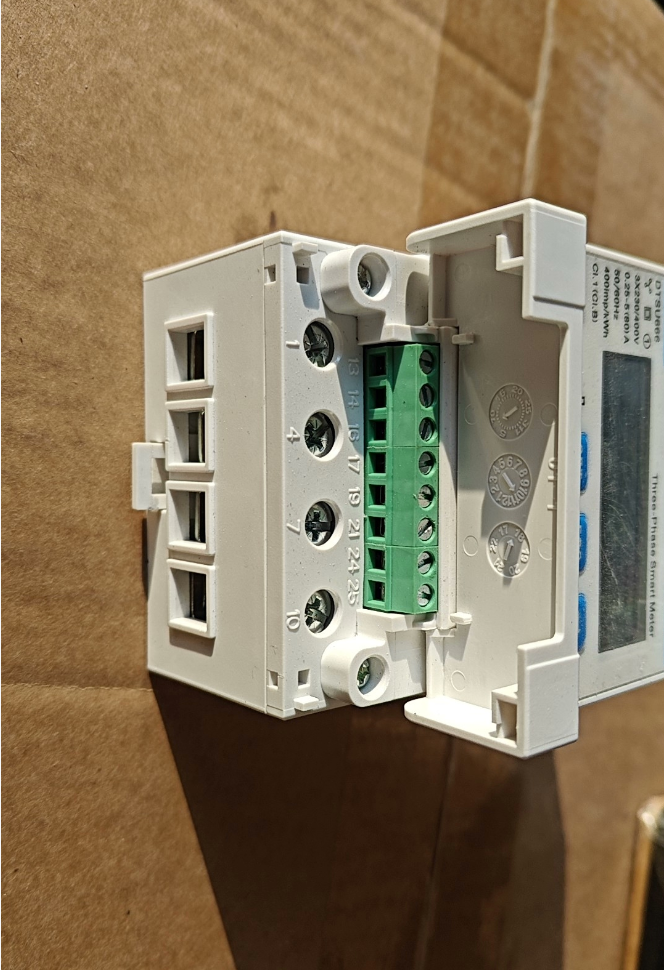
Standort: The bottom two independent terminals on the terminal block on the right side of the meter (usually marked as terminals 24 Und 25). Some models may be marked “A+” Und “B-“.
Aussehen: Same structure as power input/output terminals, screw-crimp terminals (brass material, Anti-Oxidation), suitable for wire sizes 0.5–2.5 mm².
Markierungen: Clearly printed “A+” (RS485+) Und “B-” (RS485-) next to the terminals. Some early models only show numbers 24 Und 25, with the correspondence: 24 = A+, 25 = B-.
Schutz: Same protection class as the main meter body (IP20), suitable for installation in power distribution cabinets to prevent direct finger contact with live parts.
1.2 Physical Diagram Description
[Right Side View of Chint DTSU666-G Meter]
┌─────────────────────────────┐
│ L1 L2 L3 N (Stromanschlüsse) │
│ IN1 IN2 IN3 IN4 (Current Terminals) │
│ P+ P- (Pulse Output Terminals) │
│ A+ B- (RS485 Communication Terminals) │ ← RS485 Interface Position
└─────────────────────────────┘
- Terminal Definition and Electrical Characteristics
2.1 Standard Terminal Definition Table
| Terminal-Nr. | Markierung | Signal Name | Beschreibung | Verkabelungsanforderungen |
| 24 | A+ | RS485+ | Positive differential signal | Connect to RS485+ (A) of host/PLC, using shielded twisted‑pair core |
| 25 | B‑ | RS485‑ | Negative differential signal | Connect to RS485‑ (B) of host/PLC, using shielded twisted‑pair core |
| – | GND (opt) | Signal Ground | Common ground reference (einige Modelle) | Single‑point grounding to avoid interference; empfohlen |
2.2 Elektrische Parameter (same as standard DTSU666)
Kommunikationsprotokoll: Standard Modbus-RTU (for new energy applications), compatible with DL/T645-2007
Baudrate: 1200 / 2400 / 4800 / 9600 (Standard) / 19200 bps
Data Format: 8 Datenbits + 1 Stoppbit, parity configurable (Standard: keine Parität)
Communication Distance: Max. 1200 Meter (standard RS485 bus); shielded twisted-pair recommended
Networking Capacity: Bis zu 32 devices on one bus; unique address (1–247) required for each device
- Wiring Specifications and Notes
3.1 Standard Wiring Procedure
- Select shielded twisted-pair cable (cross-section ≥ 0.5 mm²), length not exceeding 1200 Meter.
- Strip approximately 5 mm of insulation to expose the copper core, avoiding loose strands.
- Insert the A+ wire into terminal 24 and B- wire into terminal 25; Ziehen Sie die Schrauben fest (Drehmoment: 2.5 N·m).
- Apply single-point grounding to the shield (preferably at the host end) to avoid ground loops and interference.
- Use daisy-chain wiring for multi-meter networking; star topology is prohibited. A 120 Ω terminating resistor may be added at both ends of the bus.
3.2 Common Errors and Troubleshooting
A+/B- reversed: Complete communication failure; swap the two wires to restore.
Unshielded cable used: Unstable communication, susceptible to electromagnetic interference; replace with shielded twisted-pair.
Duplicate addresses: Some meters unresponsive; set unique addresses (1–247) for each meter.
Excessively long bus: Signal attenuation beyond 1000 Meter; add RS485 repeater to extend distance.
- Unterschiede zum Standard DTSU666
The physical appearance of the RS485 interface is identical between the Chint DTSU666-G (new energy dedicated) and the standard DTSU666. The main differences are:
- Default Protocol: DTSU666-G defaults to Modbus-RTU (common for PV and energy storage); standard version defaults to DL/T645-2007.
- Aktualisierungsrate: Active power refresh rate ≤ 50 ms on DTSU666-G (for fast inverter response); ca. 100 ms on standard version.
- Metering Function: DTSU666-G supports bidirectional metering (forward/reverse active/reactive power), suitable for PV self-consumption and grid-feed scenarios.
The RS485 communication interface of the Chint DTSU666-G consists of built-in screw-crimp terminals located at the lower right of the meter, marked A+/B- (Terminals 24/25). It uses a standard RS485 differential signal design and supports shielded twisted-pair wiring. Strictly distinguish A+ and B- during wiring and ensure consistent parameters with the host to achieve stable remote power data acquisition.
Would you like me to provide a ready-to-copy RS485 wiring and communication parameter configuration list based on your host or PLC model?

