 Schütz,Leistungsschalter,Sensor,Encoder,SPS,Konverter

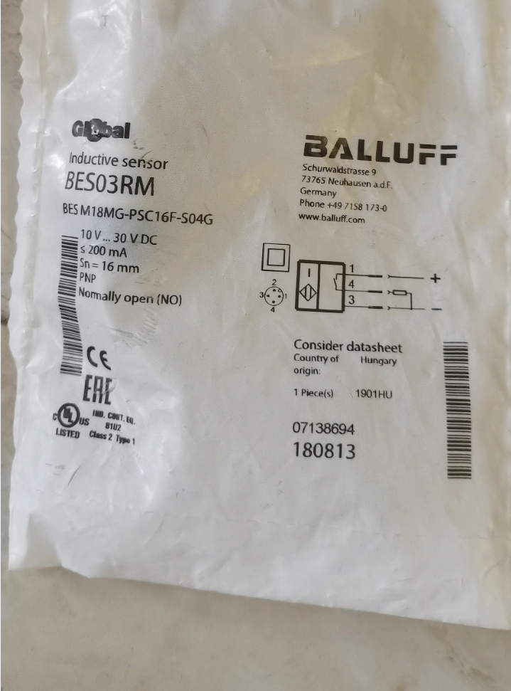

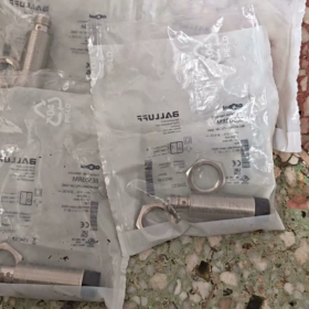
Bestell-Nr.: BES03RM; Vollständiges Modell: BES M18MG-PSC16F-S04G, M18-thread non-flush mount inductive Näherungssensor.
Erklärung des Modellcodes
M18: M18×1 cylindrical threaded housing
MG: Nicht bündige Montage, extended sensing range
P: PNP-Ausgang
SC: 3-Draht DC
16F: Nominal sensing distance 16 mm
S04G: M12-A-coded male connector, 3-Stift
Kernelektrik & Mechanische Spezifikationen
| Artikel | Spezifikation |
| Erfassungsabstand | 16 mm (nicht bündig) |
| Ausgabe | PNP-NO, normalerweise offen |
| Versorgungsspannung | 10-30 VDC |
| Max. Laststrom | 200 mA |
| Schaltfrequenz | 430 Hz |
| Schutz vor Eindringen | IP68 |
| Betriebstemperatur | -40 … +85 ℃ |
| Gehäuse | Messing vernickelt; Gesicht spüren: PBT-Kunststoff |
| Abmessungen | M18×1, overall length 66 mm |
| Verbindung | M12‑3‑pin male plug |
| Schutzmaßnahmen | Verpolungsschutz, Kurzschlussschutz, Überlastschutz |
| Gewicht | 52 G |
| HS-Code | 85365019 |
M12-3-pin Pin Assignment (Male Connector)
- Braun: DC+ (10-30V)
- —— (Nicht verbunden)
- Blau: 0V/GND
- Schwarz: Signalausgang (PNP)
Notiz: This is a 3-pin M12, not standard 4-pin. Select M12-A-coded 3-core cable for procurement.
Installationsrichtlinien
- Non-flush type. Nicht vollständig in die Metallhalterung einsinken; Die Vorderseite des Sensors muss aus der Metalloberfläche herausragen.
- Mittenabstand zwischen benachbarten Sensoren ≥36 mm, um gegenseitige Beeinflussung zu verhindern.
- Die LED befindet sich an der Steckerwurzel, 360° sichtbar; LED leuchtet bei Zielerkennung.
Gängige Ersatzoptionen
Original Balluff Äquivalent
BES M18MG-NSC16F-S04G (BES03RN): Gleiche Dimension & Erfassungsbereich, NPN-Schließer-Version.
Inländische kompatible Alternativen (M18 nicht bündig,16 mm,PNP-NR,M12-Stecker)
Innovation: IS-M18-16PO-M12
Huong: LJ18A3-16-Z/BY-G (M12-Steckervariante)
Ersatzkontrollpunkte: Bestätigen Sie den Erfassungsabstand von 16 mm, Nicht bündige Montage, PNP-NR, M12-3-polig, 10-30VDC-Versorgung.
Typische Anwendungen
Erkennung von Metallteilen an Montagelinien, Grenzwerterkennung für Werkzeugmaschinen, Bestätigung der Förderbandposition, Lagerung & Logistik, Einsatz in rauer Umgebung (niedrige Temperatur, Staub, Wasserspritzer).
Balluff BES03RM (BES M18MG-PSC16F-S04G) Komplettes Installationshandbuch
Bestell-Nr.: BES03RM, Vollständiges Modell: BES M18MG-PSC16F-S04G, Nichtbündiger induktiver Näherungssensor M18
- Produktübersicht
- Typ: Induktiver Näherungsschalter, nicht bündig (nicht flächenbündig einsetzbar)
- Gehäuse: M18×1 Messing vernickelt; Aktive Fläche Technischer Kunststoff PBT
- Schaltabstand: Nomineller Sn=16mm, effektiver Schaltabstand Sr≈16mm
- Ausgabe: PNP NO normalerweise offen, 3-Kabel DC 10–30 VDC, max. Belastung 200mA
- Schnittstelle: M12-A-kodierter 3-poliger Stecker (NICHT 4-polig)
- Bewertung: IP68; Betriebstemperatur -40℃~+85℃; Schaltfrequenz 430Hz
- Standardzubehör: 2 Stück M18 Sicherungsmuttern
- Mechanische Installationsspezifikationen (Kritisch: Versenken Sie niemals einen nicht bündigen Sensor in einer Metallbohrung)
⚠️Dies ist ein nicht bündiger Sensor. Die aktive Fläche darf nicht in metallische Befestigungslöcher eintauchen. Ein Absinken führt zu einem erheblichen Verlust der Erfassungsreichweite, Fehlauslösung oder Nichterkennung von Zielen.
2.1 Abmessungen (Einheit: mm)
Faden: M18×1
Gesamtlänge: 66 mm
Status-LED an M12-Steckerwurzel, 360° sichtbar; Die LED leuchtet, wenn ein Metallziel erkannt wird
Schlüsselweite der Mutter sichern: 24 mm
2.2 Montagedrehmoment
Anzugsdrehmoment der Kontermutter: 15-20 N·m, maximal 25 N·m. Eine Überschreitung führt zum Abisolieren des Gewindes oder zum Reißen des Gehäuses.
2.3 Abstand zwischen mehreren Sensoren
Mittenabstand zwischen identischen Sensoren ≥36 mm, um Fehlschaltungen durch Übersprechen zu vermeiden
Mindestabstand zwischen Sensorseitenwand und nahegelegener Metallwand ≥18 mm; Das Metall darf den Sensorkörper nicht berühren
Referenzziel: 18×18 mm Stahlplatte; Kleinere tatsächliche Ziele verringern die effektive Erfassungsreichweite.
2.4 Arbeitsabstand zum Ziel
Empfohlener Betriebsabstand: 4-12 mm; Maximaler zuverlässiger Betriebsspalt ≤14 mm; Vermeiden Sie einen Dauerbetrieb an der 16-mm-Grenzschwelle.
Die aktive Fläche muss so senkrecht wie möglich zum Metallobjekt zeigen; Neigungswinkel vorzugsweise <15°. Eine größere Neigung verringert den effektiven Erfassungsabstand.
- Elektrische Verkabelung (M12-A-kodierte 3-polige Steckerbelegung)
| M12 Pin-Nr. | Drahtfarbe | Funktion |
| 1 | Braun | DC+-Stromversorgung 10–30 V DC |
| 2 | — | Nicht verbunden, keine interne Verkabelung |
| 3 | Blau | 0V / GND |
| 4 | Schwarz | PNP-Signalausgang (NEIN Normalerweise geöffnet) |
❗Verwenden Sie M12-A-kodierte 3-adrige Kabel mit Buchsenende. Standardmäßige 4-adrige M12-Kabel sind ebenfalls akzeptabel, Lassen Sie Pin2 unbeschaltet.
Eingebaute elektrische Schutzvorrichtungen
Verpolungsschutz, Ausgangskurzschlussschutz, Überlastschutz.
SPS-Anbindung: Anschluss an digitales Eingangsmodul vom PNP-Typ.
Induktive Lasten (Relaisspulen): Bringen Sie die Freilaufdiode umgekehrt parallel zu den Spulenanschlüssen an.
Widerstandslasten: Halten Sie den Laststrom auf ≤200 mA.
Verbotene Operationen
- Legen Sie KEINE Wechselspannung an; Nur 10–30 VDC DC-Versorgung zulässig.
- Verlegen Sie Sensorkabel getrennt von Hochleistungskabeln, um elektromagnetische Störungen zu minimieren.
- Verfahren zur Inbetriebnahme beim Einschalten
- Vervollständigen Sie die gesamte Verkabelung; Stellen Sie sicher, dass keine Kurzschlüsse vorliegen, bevor Sie Strom anlegen.
- Kein Metallziel vorhanden: LED AUS.
- Bewegen Sie das Stahlziel in Richtung der aktiven Fläche: Die LED leuchtet innerhalb des Erfassungsbereichs auf; Die LED erlischt, nachdem das Ziel entfernt wurde.
- Ziel wiederholt durchlaufen: Bestätigen Sie ein stabiles EIN/AUS ohne Flackern.
Dieser Sensor verfügt über kein Empfindlichkeitspotentiometer. Schaltabstand kann nicht elektronisch eingestellt werden; Stellen Sie nur den mechanischen Abstand ein.
- Umgebungsbedingungen für den Betrieb
- Die Schutzart IP68 ermöglicht das vorübergehende Eintauchen in Wasser; Ziehen Sie den M12-Stecker vollständig fest, Eine schlechte Abdichtung verschlechtert die IP-Schutzart.
- Betriebstemperatur -40℃~+85℃; Wählen Sie für kalte Umgebungen Niedertemperaturkabel.
- Vermeiden Sie starke Stöße auf die PBT-Sensorfläche; Vermeiden Sie die Exposition gegenüber Schweißspritzern.
- Fehlerbehebung
| Symptom | Überprüfen Sie die Artikel |
| LED leuchtet nie | Überprüfen Sie die 10-30-VDC-Versorgung, braun/blaue Verkabelung, Vollständig sitzender M12-Stecker |
| LED immer AN ohne Ziel | 1. Sensor in Metallbohrung versenkt (häufigster Fehler); 2. Nahe gelegenes Metall zu nah am Sensorgehäuse; 3. Unzureichender Abstand zwischen den Sensoren; 4. Kurzschluss am Ausgang |
| Unterbrochenes Flackern, wenn das Ziel ankommt | Betriebsspalt nahe der 16-mm-Grenze; Metallstörungen in der Nähe; EMI von Stromkabeln; Untergroßes Ziel |
| LED AUS, auch wenn das Ziel vorhanden ist | Verdrahtungsfehler; zu große Ziellücke; Nichteisenhaltiges Ziel (Al/Cu verringern die Sensorleistung) |
- Offizieller Dokumentationszugriff
Suchen Sie auf der offiziellen Website von Balluff nach der Bestellnummer BES03RM. Geben Sie die Produktseite ein, Laden Sie das Originaldatenblatt und die 2D/3D-CAD-Dateien unter der Registerkarte „Downloads“ herunter.
Allgemeine Installationsdokument-ID für induktive Sensoren mit erweitertem Bereich: 939229.
- Ersatzteil & Ersatzreferenzen
- NPN-Gegenstück: BES03RN (BES M18MG-NSC16F-S04G)
- Inländisch kompatibel: M18 nicht bündig,16 mm,PNP-NR,M12-3-poliger Stecker.
Balluff BES03RM (BES M18MG-PSC16F-S04G) Vollständiges technisches Datenblatt
Bestell-Nr.: BES03RM; Vollständiges Modell: BES M18MG-PSC16F-S04G
Typ: Zylindrischer, nicht bündig montierter induktiver Näherungssensor M18
Grundlegende Informationen
| Artikel | Spezifikation |
| Funktionsprinzip | Induktiv, erkennt metallische Ziele |
| Montageart | Nicht bündig, kann nicht bündig in Metallbohrungen eingebaut werden |
| Gehäuse | M18×1 Außengewinde, Messing vernickelt |
| Material der aktiven Fläche | Technischer PBT-Kunststoff |
| Gesamtabmessungen | Φ18mm × Gesamtlänge 66mm |
| Schlüsselweite der Kontermutter | 24 mm, 2 Sicherungsmuttern im Lieferumfang enthalten |
| Gewicht | 52 G |
| HS-Code | 85365019 |
| Zulassungen | CE, UKCA, cULus, WEEE, konform mit IEC60947-5-2 |
Sensorleistung
| Artikel | Spezifikation |
| Nennschaltabstand Sn | 16 mm |
| Effektiver Betriebsabstand Sr | 12.8 ~19,2mm |
| Referenzziel | 18 mm×18mm×1mm Stahlplatte |
| Schaltfrequenz | 430 Hz |
| Hysterese | ≤10 % Sn |
| Empfindlichkeitseinstellung | Nicht verstellbar (fester Bereich) |
Elektrische Nennwerte
| Artikel | Spezifikation |
| Versorgungsspannung Ub | 10 ~30 VDC |
| Leerlaufstrom | ≤8mA |
| Ausgabetyp | PNP normalerweise geöffnet (NEIN), 3-Draht DC |
| Max. Laststrom | 200 mA |
| Eingebaute Schutzvorrichtungen | Umgekehrte Polarität, Kurzschluss, Überlastschutz |
| Statusanzeige | LED an der M12-Steckerwurzel, 360° sichtbar; leuchtet, wenn Metall erkannt wird |
| Schnittstelle | M12-A-kodierter 3-poliger Stecker (NICHT 4-polig) |
M12-3-polige Pinbelegung
| Pin-Nr. | Drahtfarbe | Funktion |
| 1 | Braun | DC+-Stromversorgung 10–30 VDC |
| 2 | — | Nicht verbunden |
| 3 | Blau | 0V / GND |
| 4 | Schwarz | PNP-Signalausgang NO Normalerweise offen |
Kabelempfehlung: M12-A-kodiertes Buchsenende, 3-Kernkabel. 4-Kernkabel verwendbar, wenn Pin2 offen bleibt.
Mechanisch & Umweltbewertungen
| Artikel | Spezifikation |
| Schutz vor Eindringen | IP68 (Stecker vollständig festgezogen) |
| Betriebstemperatur | -40℃ ~ +85℃ |
| Empfohlenes Drehmoment der Sicherungsmutter | 15-20 N·m; Absolut maximal 25 N·m, um Gewindeschäden zu vermeiden |
| Vibrationsfestigkeit | 10-55Hz, Amplitude1mm, IEC60068-2-6 |
| Schockfestigkeit | 30 G / 11 MS, IEC60068-2-27 |
Regeln für den Installationsabstand
- Benachbarte baugleiche Sensoren: Mitte-zu-Mitte ≥36 mm zur Vermeidung von Übersprechen.
- Mindestabstand zwischen Sensorseite und Metallwand: ≥18mm.
- Vorgeschlagene Arbeitslücke: 4-12 mm; Vermeiden Sie Dauerbetrieb in der Nähe der Schwelle von 14–16 mm.
- Halten Sie das Ziel senkrecht zur Erfassungsfläche; Neigungswinkel <15°, Der Erfassungsabstand nimmt mit größerer Neigung ab.
Zugehörige Original-Teilenummern
- BES03RN (BES M18MG-NSC16F-S04G): gleich mechanisch & Reichweite, NPN normalerweise offen.
Wichtige Hinweise
- Nicht bündiger Sensor: Die aktive Fläche muss über die metallische Montagefläche hinausragen. Sinken führt zu einer Verschlechterung der Reichweite, Fehlschaltung oder keine Erkennung.
- Nur DC-Gerät, Wechselstromeingang verboten.
- Bei induktiven Lasten, z. B. in einem Schaltkreis, eine rückwärtsparallele Freilaufdiode einbauen. Relaisspulen.
- Trennen Sie Sensorsignalkabel von Hochleistungsstromkabeln, um elektromagnetische Störungen zu reduzieren.
Kurze Zusammenfassung zur Fehlerbehebung
LED dauerhaft AN ohne Ziel: Wahrscheinlich versunkene Installation, Metallstörungen in der Nähe oder unzureichender Abstand zwischen den Sensoren.
Flackern bei Erkennung: Arbeitsspalt nahe der maximalen Grenze von 16 mm; Reduzieren Sie den mechanischen Spalt.
LED leuchtet nie: Versorgungsspannung überprüfen, M12-Steckeraufnahme und braun-blaue Stromverkabelung.





NH42-63-318x560.png "Automatische Transferschalter vom Typ CHINT PC (ATS)NH42-63/4SZ")



