 Schütz,Leistungsschalter,Solarwechselrichter,Stromzähler,Solarbatterien

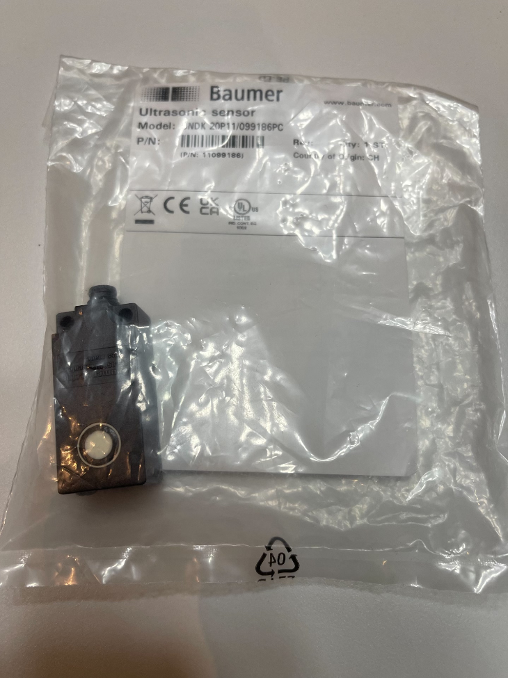

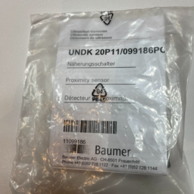
UNDK20P11
- UNDK: Integrated transmit-receive rectangular ultrasonic sensor Serie
- 20: 20mm housing width, compact block housing
- P: PNP transistor output
- 11: Standard switching type, fixed measuring range, M8-Stecker, Normalerweise geöffnet (NEIN) Ausgabe
Material-Nr.: 099186
- Grundlegende elektrische Spezifikationen
| Parameterelement | Spezifikationswert |
| Versorgungsspannung | DC 15~30V (UL Class2) |
| Static Power Consumption | ≤55mA |
| Ausgabetyp | 3-wire PNP Normally Open (NEIN) |
| Max. Laststrom | 200mA |
| Switch Hysteresis | Typisch 4% of full range |
| Antwort / Release-Zeit | ≤35ms |
| Ultrasonic Frequency | 380kHz |
| Adjustment Method | On-body Teach-in self-learning calibration |
| Indicators | Yellow LED (Schaltzustand), Red LED (fault / target indication) |
III. Measuring & Ranging Specifications
Messbereich: 40mm~400mm
Dead zone Sdc: 40mm (unstable detection below 40mm)
Wiederholen Sie die Genauigkeit: <0.5mm
Auflösung: <0.3mm
Sound Beam Angle: Standard narrow beam, suitable for narrow stations and adjacent interference suppression
- Mechanisch & Protection Specifications
- Overall dimension: Rectangular block, 42mm (L) × 20mm (W) × 15mm (T)
- Gehäusematerial: PA12 engineering plastic; sound transducer head: POM
- Elektrische Schnittstelle: M8 4-pin male connector (S35A standard plug)
- Schutzklasse: IP67, staubdicht und spritzwassergeschützt
- Betriebstemperatur: -10℃~+60℃
- Anti-interference Performance: Resistant to dust, moisture and mist; unaffected by target color, transparency or metal materials
- Pin-Belegung (M8 4Pin)
- Pin1: Brown → DC24V Positive
- Pin2: White → Teach-in input
- Pin3: Blue → 0V GND Negative
- Pin4: Black → PNP switching output
- Typische Anwendungsszenarien
- Verpackungsmaschinen: Material presence detection, carton position confirmation, transparent plastic bottle inspection
- Logistics Conveying: Workpiece counting, object presence detection, low-level bin warning
- Lithiumbatterie / 3C Industry: Small workpiece positioning, thin transparent material detection (for environments where photoelectric sensors fail)
- Holzbearbeitung & Textile Industry: Replace photoelectric sensors in dusty environments; stable detection for non-reflective materials
VII. Reference Alternative Models in the Same Series
- UNDK20N11: Gleiche Abmessungen & measuring range, NPN Normally Open output
- UNDK20P6914: Analog 4–20mA ranging version (continuous distance signal output)
- UNDK20P17: Long-range version, 100–1000mm measuring range
VIII. Produktvorteile
- Ultra-small 40mm dead zone, compact 20mm block design for limited installation space
- One-touch Teach key to set switching threshold; no tools required for commissioning
- Immune to interference from transparent, black and mirror surfaces, superior to photoelectric sensors
- IP67 industrial protection, compatible with humid and heavily dusty production lines
Baumer UNDK20P11 Ultrasonic Sensor Installation & Bedienungsanleitung
Document Version: V1.0 | Applicable Model: UNDK20P11 (Material-Nr. 099186)
Table of Contents
- Pre-installation Safety Instructions
- Auspacken & Product Specification Verification
- Mechanische Installationsspezifikationen (Abmessungen, Brackets, Abstand, Interference Prevention)
- Electrical Wiring Definition & Wiring Procedures
- Complete Teach-in Calibration Process
- Environmental Installation Restrictions & Forbidden Working Conditions
- Isolation Standards for Side-by-Side / Opposed Multi-sensor Installation
- Power-on Verification & Fehlerbehebung
- Routinewartung & Storage Specifications
- Quick Reference Technical Parameter Table
1 Pre-installation Safety Instructions
- Disconnect the 24V DC power supply before wiring, disassembly or assembly. Hot plugging/unplugging of M8 connectors is strictly prohibited to avoid breakdown and burnout of output transistors.
- Only DC 15~30V power supply is permitted; AC power and high-voltage power supply are forbidden.
- The maximum load current of PNP output is 200mA. A freewheeling diode must be connected in parallel across inductive loads such as solenoid valves and relays (reverse parallel on both ends of the coil).
- Do not install the sensor at close proximity to strong ultrasonic sound sources (high-pressure washers, ultrasonic welding machines, high-frequency pneumatic nozzles), which will cause false triggering.
- The housing is made of PA12 plastic. Do not strike the sound-emitting surface with sharp hard objects, and avoid direct spraying of strong acid or strong solvent onto the transducer head.
- Only suitable for standard indoor industrial environments; a rainproof protective cover is mandatory for outdoor use.
2 Auspacken & Product Verification
2.1 Standard Package List
1 × UNDK20P11 ultrasonic sensor main unit
1 × Short product instruction sheet
2.2 Visual Inspection Items
- No cracks on housing; no scratches or oil contamination clogging the sound-emitting surface
- M8 4-pin male plug free of deformation; pins without bending or oxidation
- Intact side Teach key; transparent red/green LED windows without damage
2.3 Quick Reference Basic Parameters
Messbereich: 40mm (dead zone) ~ 400mm (maximum detection distance)
Ausgabe: 3-wire PNP NO (Normalerweise geöffnet)
Ultrasonic frequency: 380kHz
Schutzklasse: IP67
Betriebstemperatur: -10℃ ~ +60℃
3 Mechanische Installationsspezifikationen
3.1 Gesamtabmessungen (Einheit: mm)
Total length 42 × width 20 × thickness 15, compact block housing.
3.2 Standard Installation Methods
Method A: Aluminum Profile Groove Bracket Mounting (Empfohlen)
- Use plastic or metal snap brackets matched with standard 20mm aluminum profiles to wrap both sides of the sensor body.
- Tightening torque of fixing screws shall be controlled at 0.4~0.6N·m. Do not compress the housing with excessive force to prevent damage to internal piezoelectric crystals.
- The sound-emitting surface shall face the measured object vertically; a slight inclination of ±10° is allowed. Excessive tilt will drastically reduce detection stability.
Method B: Sheet Metal Cutout Fixing
- Cutout dimension: 21mm × 16mm; chamfer and deburr cutout edges.
- Non-flush mounting of the sensor: The transducer head shall protrude at least 5mm outward from the sheet metal.
- Sheet metal tightly attached to both sides of the head will reflect ultrasonic waves, resulting in enlarged dead zone and frequent false detection.
3.3 Mandatory Key Installation Distance Requirements
- Minimum dead zone: The distance between target and transducer head shall not be less than 40mm; targets within 40mm cannot be detected.
- Maximum effective detection distance: 400mm; no signal output beyond this range.
- No metal brackets, cables or bolts shall be fixed within the 120° sound beam in front of the head to avoid blocking ultrasonic waves.
- Minimum target width: Stable detection requires target width ≥25mm at a distance of 200mm.
3.4 Environmental Taboos for Single Sensor Installation
Continuous water dripping or direct mist spray above / beside the transducer head is forbidden.
Keep away from fans, air guns and high-pressure blow nozzles (airflow disturbs ultrasonic echoes).
Long-term operation in silicone volatile environments (silicone glue, silicone oil seals) will clog the sound diaphragm.
4 Electrical Wiring Definition & Betrieb
4.1 M8 4-Pin Male Connector Pinout
| Pin-Nr. | Drahtfarbe | Funktion | Beschreibung |
| Pin1 | Braun | DC24V+ Power Positive | Supply DC 15~30V |
| Pin2 | Weiß | External Teach-in wire | Short to +24V to trigger calibration |
| Pin3 | Blau | 0V GND Power Negative | System common ground |
| Pin4 | Schwarz | PNP Normally Open Output | Outputs 24V when target is detected, max. 200mA |
4.2 Wiring Procedures
- Cut off total power and confirm no voltage output from PLC / Stromversorgung.
- Connect with standard M8 4-core female cable; cable bending radius ≥ 5 × cable outer diameter.
- Separate power cables (Motor, inverter cables) from sensor signal cables with a spacing ≥100mm to avoid inverter interference.
- Secure cables with cable ties; reserve 50mm slack at connectors to eliminate long-term tensile stress on plugs.
- Install freewheeling diodes for inductive loads: Anode of diode connects to load negative terminal, cathode connects to 24V output terminal.
4.3 Anforderungen an die Stromversorgung
Ripple voltage ≤10% of rated voltage
It is recommended to add a 1000μF filter capacitor to the switching power supply to suppress industrial grid interference
Do not share the same power circuit with high-power motors
5 Teach-in Calibration Process (Two Modes: Schlüssel / External Wire)
5.1 Single Switch Threshold Setting (Standard Operation)
Verfahren 1: On-body Key Calibration
- Power on the sensor; green LED lights steadily for standby status.
- Press and hold the side Teach key for 2 Sekunden; green LED flashes rapidly.
- Place the workpiece at the target trigger detection distance.
- Short-press the Teach key once.
- Green LED stays lit for 2 Sekunden, indicating parameter storage complete and commissioning finished.
Metho 2: External Calibration via White Teach Wire (PLC Automatic Calibration Scenarios)
- Short the white wire to brown 24V positive terminal for 2s; green LED flashes.
- Place the workpiece at the preset detection distance.
- Disconnect then instantly re-short the white wire once.
- Green LED stays steady for 2s to save the threshold value.
5.2 Restore Factory Default Settings
- Press and hold the Teach key for over 6 Sekunden / keep the white wire connected to 24V for more than 6 Sekunden.
- Red and green LEDs flash alternately.
- Release the key / disconnect the white wire; factory default measuring range 40~400mm and default switch point are restored automatically.
5.3 LED Indicator Status Description
| LED Status | Equipment Status |
| Green steady on | Powered standby, no target detected |
| Yellow lit | Target detected, PNP output conducting |
| Rot & green alternate flashing | Calibration reset in progress / parameter reset successful |
| Red steady on | Fehler: Kurzschluss, wiring error, clogged sound diaphragm |
6 Multi-sensor Installation Isolation Specifications (Mutual Interference Prevention)
6.1 Side-by-Side Same-Direction Mounting (Same Detection Orientation)
Minimum center-to-center distance between two UNDK20 series sensors: ≥120mm
Insufficient spacing causes mutual ultrasonic reflection and continuous false triggering.
6.2 Opposed Face-to-Face Mounting (Heads Facing Each Other)
Vertically stagger the axes of two heads by ≥150mm; direct face-to-face installation is forbidden.
If close opposed layout is mandatory, stagger mounting heights to avoid overlapping sound beams.
6.3 Recommended Layout for Dense Multi-sensor Arrangement
- Install sensors in staggered high-low layers.
- Equip each sensor with independent aluminum profile separation baffles (ABS / metal baffles block ultrasonic waves).
- Split sensors into two groups with staggered power supply timing to avoid interference from simultaneous ultrasonic emission.
7 Power-on Inspection & Fehlerbehebungsmatrix
7.1 No LED Illumination After Power-up
- Reversed or broken brown/blue power wires
- Supply voltage lower than 15V
- Poor crimping of M8 plug pins; re-crimp the cable.
7.2 Yellow LED Steady On Without Target (Falsche Auslösung)
- Metal brackets or cables block the sound beam in front of the head
- Insufficient spacing between two sensors causing mutual interference
- Continuous airflow or mist disturbs ultrasonic echoes
- Excessively long calibrated distance via Teach-in; re-calibrate the threshold.
7.3 No Signal Output With Workpiece Present (Yellow LED Off)
- Workpiece distance falls within the 40mm dead zone
- Overly small workpiece or sound-absorbing material (thick sponge, sound-absorbing foam)
- Sound diaphragm clogged with dust and oil; wipe and clean thoroughly
- Overly close Teach-in threshold setting; re-perform Teach calibration.
7.4 Persistent Red Fault Indication
- Short-circuited output load; disconnect load and re-test
- Supply voltage exceeds 30V, burning internal circuits
- Damaged sound diaphragm; sensor replacement required.
8 Environmental Installation Restrictions & Schutz
- Temperaturbereich: -10℃ ~ +60℃. Frost on the head below -10℃ leads to failure; heating shield required.
- Schutzart IP67: Tolerates short splashing water; long-term underwater submersion and direct high-pressure water jet flushing of the head are forbidden.
- Heavy dust conditions (woodworking, Zement, lithium powder): Blow clean the sound diaphragm with dry compressed air monthly.
- Corrosive mist environments (Galvanisieren, pickling): Use sealed protective covers to isolate acid and alkali fumes.
9 Routine Maintenance Specifications
- Weekly visual inspection of transducer head surface to remove dust, oil and water stains.
- Tighten bracket mounting screws monthly to eliminate loosening caused by vibration.
- Inspect M8 connector cables quarterly for abrasion and cracking.
- Clean only with dust-free cloth and clean water; soaking the head in alcohol, acetone or thinner is prohibited.
10 Appendix: Technische Kernparameter
| Parameterelement | UNDK20P11 Specification |
| Modellreihe | UNDK20 Compact Ultrasonic Series |
| Messbereich | 40mm ~ 400mm |
| Dead Zone | 40mm |
| Ausgabetyp | PNP 3-wire Normally Open (NEIN) |
| Versorgungsspannung | DC15~30V |
| Max. Ausgangsstrom | 200mA |
| Switch Hysteresis | 4% of full range |
| Ansprechzeit | ≤35ms |
| Ultrasonic Frequency | 380kHz |
| Gehäusematerial | PA12; transducer head POM |
| Schutzklasse | IP67 |
| Schnittstelle | M8 4-pin Male S35A Connector |
| Montagemaße | 42×20×15mm |
11 Installation Acceptance Standards
Three acceptance items must be completed before putting equipment into production after installation:
- Mechanical Acceptance: No loose brackets, unobstructed transducer heads, compliant spacing for multi-sensor layout.
- Electrical Acceptance: Correct wiring, no short circuits, freewheeling diodes fully fitted for inductive loads.
- Functional Acceptance: Repeatedly insert and retract workpieces; stable sensor triggering without missing detection or false detection.
 8-Port Industrial Layer 2 Hub")


")
NH42-63-318x560.png "Automatische Transferschalter vom Typ CHINT PC (ATS)NH42-63/4SZ")


