 Schütz,Leistungsschalter,Solarwechselrichter,Stromzähler,Solarbatterien


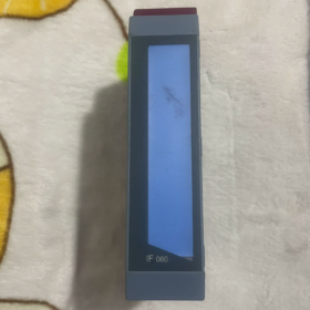
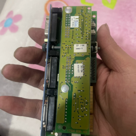
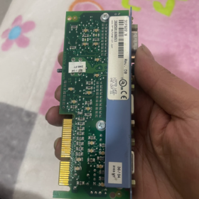
This single-slot interface expansion carrier module is designed for B&R-Automatisierung 2005 series PCC programmable controllers. It has no independent communication functions and must be used together with 3IF6xx series interface submodules to expand industrial communication protocols such as RS232, CAN and Profibus. This model has been discontinued alongside the Automation 2005 System; genuine spare parts and second-hand dismantled modules dominate the current market supply.
- Digit-by-Digit Model Code Breakdown
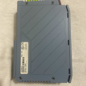
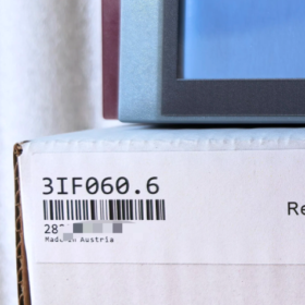
Full order number: `3IF060.6`
| Codesegment | Definition |
| 3 | Product Platform: Automation 2005 PCC control system, B&R’s second-generation mid-range PLC platform |
| IF | Produkttyp: Schnittstellenmodul, for expanding system communication capacity |
| 60 | Function Series: Single-slot interface carrier unit, basic expansion specification supporting one interface subcard |
| 0.6 | Hardware Version: 6th hardware revision, backward compatible with lower-version interface submodules of the same series |
- Full List of Core Specifications
Elektrisch & Functional Parameters
| Parameterelement | Spezifikationswert |
| Power Supply Mode | Powered via Automation 2005 system backplane bus; no separate external power supply required |
| Betriebsspannung | DC 24V (uniformly supplied by the backplane, tolerates ±25% voltage fluctuation) |
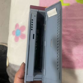
| Slot Quantity | 1 standard slot for interface submodules |
| Compatible Submodules | Full range of 3IF6xx interface subcards for Automation 2005 Systeme |
| Elektrische Isolierung | Galvanic isolation between system backplane bus and external interface side with ESD protection |
| Statusanzeigen | Power LED (Grün), Run/Fault LED (Rot) |
| Self Power Consumption | ≤ 2W (excluding inserted submodules) |
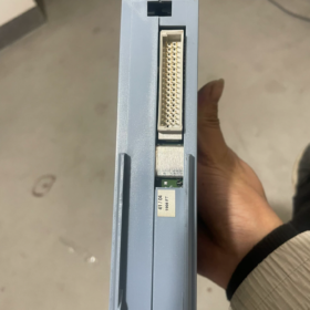
| Data Interaction | Real-time data transmission with the CPU via the Automation 2005 backplane bus |
Mechanisch & Umgebungsparameter
| Parameterelement | Spezifikationswert |
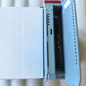
| Montagemethode | Installed into standard 3BP series backplane slots of Automation 2005 Systeme, compatible with 35mm DIN rails |
| Slot Occupation | Single slot, matching standard backplane pitch of Automation 2005 Systeme |
| Eindringschutzklasse | IP20, for cabinet installation only |
| Betriebsumgebungstemperatur | 0 ℃ ~ +55 ℃ (nicht kondensierend) |
| Lagerung / Transportation Temperature | -20 ℃ ~ +60 ℃ |
| Verschmutzungsgrad | Verschmutzungsgrad 2 per EN 61131-2 |
| Unit Weight | Ca. 0.15 kg (excluding submodules) |
III. Functional Principle & Systemarchitektur
- Kernpositionierung
The 3IF060.6 is a pure carrier expansion module without integrated communication interface chips or protocol stacks. Its core functions are as follows:
Physically bridge the Automation 2005 backplane bus and interface submodules to transmit signal paths and power supply;
Provide galvanic isolation and surge protection to shield the CPU mainboard from overvoltage and electrostatic shocks on external interfaces;
Standardized hardware interfaces enable uniform adaptation of submodules with different protocols to the system backplane for flexible expansion.
- System Expansion Logic
Multiple 3IF060.6 modules can be expanded via the backplane for one Automation 2005 CPU; the maximum expandable quantity depends on CPU performance and bus load;
Each 3IF060.6 accepts one interface submodule to expand one or multiple communication ports correspondingly;
Parsing and processing of communication protocols are completed jointly by submodule hardware and CPU programs, while the carrier module only handles signal transmission and hardware mounting.
- Matching Submodules & Compatible Devices
- Main Compatible Interface Submodules
| Submodule Model | Interface Functions | Typische Anwendungsszenarien |
| 3IF613.9 | 3 independent RS232 serial ports | Serial communication with HMIs, barcode scanners and inverter debugging ports |
| 3IF621.9 | CAN bus interface (CAN 2.0A/B) | Distributed I/O and servo drive CAN networking |
| 3IF671.9 | Profibus DP Master/Slave | Bus connection with third-party PLCs and field instruments |
| 3IF681.9 | Industrial Ethernet interface | HMI monitoring and MES system data collection |
- Compatible CPUs & Backplanes
Supported CPUs: Full range of Automation 2005 CPU modules, including 3CP100.60, 3CP260.60-1, 3CP340.60-2, usw.
Compatible Interface Processors: Programmable interface modules such as 3IF260.60-1
Supported Backplanes: Standard Automation 2005 backplanes including 3BP150.4, 3BP155.4, 3BP201.49, usw.
- Installation, Verdrahtung & Betriebsspezifikationen
- Standard Installation Steps
- Cut off the total system power supply and confirm no voltage output on the backplane;
- Align the module with the backplane slot and push it horizontally with even force until the top buckle locks into place;
- Align the interface submodule with the top slot of the 3IF060.6, insert vertically and fasten securely;
- Connect external communication cables and ensure single-point grounding of the shielding layer as required.
- Strictly Forbidden Operations
Hot plugging of modules and submodules is prohibited to avoid burning backplane bus chips;
Insert submodules horizontally only; forced oblique insertion is forbidden to prevent bending or deformation of pins;
Do not cover the module surface with foreign objects which block natural heat dissipation;
Communication cables must be routed separately from power cables with a minimum spacing of 20cm to avoid electromagnetic interference.
- Sicherheitszertifizierungen & Compliance-Standards
CE-zertifiziert, konform mit EN 61131-2 standard for programmable controllers
UL 508 certification for industrial control equipment
cULus dual certification for North America
RoHS 2.0 environmental compliance
VII. Ersatz & Upgrade-Lösungen
Lösung 1: Direct Replacement within the Same System (Minimum Modification)
Ersatzmodell: 3IF060.9 (high-version single-slot interface carrier of the same series with optimized hardware upgrades, fully backward compatible with submodules and system configurations of 3IF060.6, Plug-and-Play)
Anwendbare Szenarien: Routine maintenance of existing Automation 2005 systems without modifying control programs or hardware architecture
Lösung 2: Cross-System Upgrade Replacement (Leistungssteigerung)
Replacement Scheme: New-generation B&R X20 control system + X20IF series interface modules (z.B. X20IF1061-1 Profibus module, X20IF1082 Ethernet module, usw.)
Differenzbeschreibung: The X20 series adopts a brand-new hardware and software platform; its backplane bus, mounting dimensions and programming system are incompatible with Automation 2005 Systeme. Complete hardware and program upgrades are required, suitable for equipment renovation and replacement projects.
Lösung 3: Emergency Spare Parts Replacement
Second-hand dismantled modules: Stock dismantled 3IF060.6 modules passing functional testing can be directly replaced with the lowest cost for emergency production line maintenance
Notiz: The backplane bus of Automation 2005 systems uses B&R proprietary protocols; no fully compatible domestic third-party modules are available, and non-original counterfeit parts are not recommended.
VIII. Common Fault Troubleshooting Matrix
| Fehlerphänomen | Ursachenanalyse | Schritt-für-Schritt-Lösungen |
| No LED illumination after power-on; unrecognized by the system | Abnormal backplane power supply or poor module contact | 1. Measure 24V power supply of the backplane slot; 2. Re-insert the module and confirm full buckle locking; 3. Test on an adjacent slot to rule out backplane slot failure |
| CPU reports configuration error after inserting submodule | Poor submodule contact or outdated CPU firmware version | 1. Ausschalten, re-insert the submodule and clean oxidized gold fingers; 2. Verify the submodule model belongs to the 3IF6xx Automation 2005 Serie; 3. Upgrade CPU system firmware to the matching version |
| Intermittent communication with severe data packet loss | Failed cable shielding or strong on-site electromagnetic interference | 1. Check reliable single-point grounding of communication cable shielding layers; 2. Reduce communication baud rate for stability testing; 3. Locate interference sources such as inverters and servo drives and implement shielding isolation |
| Constant red fault LED, complete communication interruption | Damaged submodule hardware or short-circuited interface | 1. Test with an identical submodule to locate the faulty component; 2. Check external interfaces for traces of short circuits or overvoltage surges; 3. Measure the resistance of interface pins to ground to judge whether the interface chip is burnt out |
Complete List of Compatible Submodules for B&R 3IF060.6
The 3IF060.6 is a single-slot interface carrier module of B&R-Automatisierung 2005 Serie. It has no independent communication functions and is only compatible with pluggable 3IF6xx series interface submodules of the same platform. Below is the full list of officially certified compatible submodules sorted by function.
- Full List of Compatible Submodules
- Serial Communication Series
| Submodule Model | Schnittstellenkonfiguration | Kernbeschreibung |
| 3IF613.9 | 3 independent RS232 serial ports | The subcard with the largest number of serial ports in the full series, with galvanically isolated ports for connecting multi-serial devices such as HMIs, barcode scanners, serial instruments and inverter debugging ports |
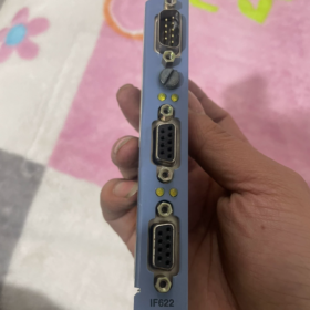
| 3IF622.9 | 1×RS232 + 2×RS485/RS422 | All ports galvanically isolated, supports Modbus RTU and free protocols, covering debugging serial ports and bus-type serial devices |
- Seriell + CAN Combined Series
| Submodule Model | Schnittstellenkonfiguration | Kernbeschreibung |
| 3IF621.9 | 1×RS485/RS422 + 1×CAN 2.0A/B | Most cost-effective universal combination; CAN port supports protocols including CANopen for distributed I/O and servo drive networking, with an extra serial port reserved for debugging |
| 3IF671.9 | 1×RS232 + 1×RS485/RS422 + 1×CAN | Full-function triple-interface combination covering debugging, serial bus and CAN bus scenarios; multi-protocol expansion realized via one single card |
| 3IF672.9 | 1×RS232 + 2 independent CAN interfaces | Dual CAN channel design supporting dual bus redundancy or segmented network isolation, suitable for complex systems with multi-branch CAN networks |
- Main Fieldbus Series
| Submodule Model | Schnittstellenkonfiguration | Kernbeschreibung |
| 3IF661.9 | 1×Profibus DP (RS485 physical layer) | Galvanically isolated, supports both Master and Slave modes for connection with Profibus-compliant equipment including third-party PLCs, field instruments and drives |
- Industrial Ethernet Series
| Submodule Model | Schnittstellenkonfiguration | Kernbeschreibung |
| 3IF686.9 | 1×POWERLINK real-time Ethernet interface | Supports Managing Node (MN) and Controlled Node (CN) modes with galvanic isolation, for B&R real-time Ethernet bus networking to connect remote I/O and servo systems |
- Key Compatibility Notes
- Platform Restriction: Only compatible with exclusive 3IF6xx subcards for Automation 2005 Systeme. Interface modules of other series including X20, X67 and ACOPOS are incompatible in physical structure and bus protocols and cannot be inserted.
- Slot Restriction: The 3IF060.6 is a single-slot carrier and accepts only one submodule at a time; stacked expansion is not supported.
- Version Compatibility: Hardware suffixes of submodules (z.B. .9) are backward compatible. Higher-version subcards operate normally on the .6 version carrier without modifying system configurations or programs.
- Custom Models: Some industry-customized submodules (z.B. special protocol versions such as 3IF681.86) require CPU firmware version verification; some low-version firmware may fail to recognize them properly.
III. Common Model Selection Recommendations
Multi-serial device connection: Prioritize 3IF613.9
CAN-Bus + basic serial port: Prioritize 3IF621.9
Connection with Siemens and other Profibus systems: Select 3IF661.9
Native B&R real-time Ethernet expansion: Select 3IF686.9
 8-Port Industrial Layer 2 Hub")


")
NH42-63-318x560.png "Automatische Transferschalter vom Typ CHINT PC (ATS)NH42-63/4SZ")


