 Schütz,Leistungsschalter,Solarwechselrichter,Stromzähler,Solarbatterien


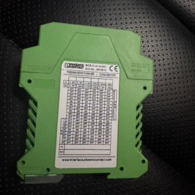
- Erläuterung der Aufschlüsselung des Modellcodes
| Codesegment | Definition |
| MCR | Kennung der Basisserie: Modularer Strom-/Spannungswandler, Serie von 3-Wege-isolierten Signalaufbereitern |
| C | Maßangabe: Standardbreite (17.5mm), unterscheidet sich von der MINI MCR-Serie (6.2mm/12,5 mm) |
| Benutzeroberfläche | Eingabetyp: Universeller Eingang, unterstützt 0–10 V Spannung & 4–20mA Stromsignale |
| Benutzeroberfläche | Ausgabetyp: Universeller Ausgang, unterstützt 0–10 V Spannung & 4–20mA Stromsignale |
| DCI | Funktionsmerkmal: DC-Isolierung; Der eingebaute DC/DC-Wandler ermöglicht eine 3-Port-Isolierung zwischen den Eingängen / Ausgabe / Stromversorgung |
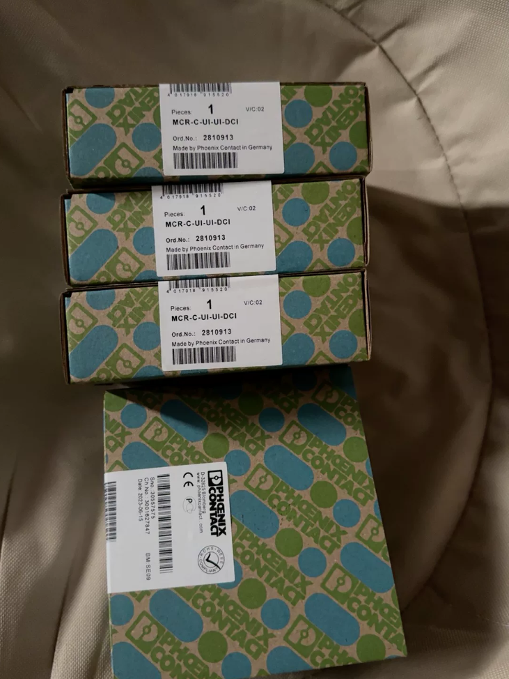
| 2810913 | Eindeutige Bestellnummer: Offiziell Phönix Teilenummer für die Beschaffung & Bestandsverwaltung |
- Datenblatt zur Kernspezifikation
2.1 Grundlegende elektrische Spezifikationen
| Parameter | Wert | Bemerkung |
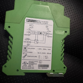
| Isolationstyp | 3-Weg Isolation (Eingang / Ausgabe / Leistung) | Spannungsprüfung standhalten: Rein-Raus:1.5kV Wechselstrom; Stromsignal:1kV Wechselstrom (50Hz, 60S) |
| Eingangssignal | 0–10V DC / 4–20mA Gleichstrom | Max. Eingang:30V / 50mA |
| Ausgangssignal | 0–10V DC / 4–20mA Gleichstrom | Max. Ausgabe:15V / 30mA |
| Übertragungsfehler | ≤0,1 % FS | Hochpräzise Signalwandlung |
| Stromversorgung | 18–30V DC | Nominal 24 V DC; Leerlaufstrom <30mA |
| Stromverbrauch | ≤900mW | Unter Nennbetriebsbedingungen |
| Grenzfrequenz | 30Hz | 3dB-Punkt, Hochfrequenzstörungen effektiv unterdrücken |
| Schrittantwort | 11MS (10%–90 %) | Schnelle Signalverfolgungsleistung |
2.2 Mechanisch & Umweltspezifikationen
| Parameter | Wert | Bemerkung |
| Gesamtdimension | B17,5 mm × H99 mm × T114,5 mm | Platzsparende DIN-Schienenmontage |
| Montage | Standardmäßige 35-mm-DIN-Schiene | Beliebige Einbauausrichtung möglich |
| Beendigung | Steckbare Schraubklemme (COMBICON) | Abisolierlänge:8mm, M3-Schraubgewinde |
| Kabelgröße | Solide/flexibel:0.2–2,5 mm² (AWG24–14) | Kompatibel mit verschiedenen Industriekabeln |
| Betriebstemp. | -20°C ~ +65°C | Großer Temperaturbereich für industrielle Umgebung |
| Eingangsbewertung | IP20 | Nur Schrankinstallation im Innenbereich |
| Gewicht | 149.4G (mit Paket) | Leicht für einfache Montage |
2.3 Zertifizierung & Einhaltung
| Zertifizierung | Standard | Bemerkung |
| CE | IN 61000-6-2 / IN 61000-6-4 | EMV-konform |
| UL-anerkannt | UL 508 | Klasse I Div.2 Gruppen A-D; Klasse I, Zone2, Gruppe IIC |
| Öko-Zertifikat | EU RoHS / China RoHS | EFUP-50 (50-Jahr Lebensdauer für Umweltkonformität) |
| HS-Code | 85437090 | Für die Zollabwicklung im internationalen Handel |
- Vollständige Liste der Teilenummern der Serie (MCR-C-UI-UI-DCI-Familie)
| Bestell-Nr. | Modell | Besonderheit | Typische Anwendung |
| 2810913 | MCR-C-UI-UI-DCI | Standardversion, Werksvoreinstellung 0–10 V/0–10 V | Allgemeine industrielle Signalisolierung & Konvertierung |
| 2810939 | MCR-C-UI-UI-DCI-NC | NC = Keine Kalibrierung | Feste Anwendung ohne Kalibrierung vor Ort |
| 2811284 | MACX MCR-UI-UI | Verbessertes Ersatzmodell | Neue Generation mit verbesserter Leistung |
| 2810915 | MCR-C-UI-UI-450-DCI | Hochlasttyp, Max. Ausgangslast ≤450Ω | Signalübertragung über große Entfernungen & Hochlastanlässe |
| 2810941 | MCR-C-UI-UI-450-DCI-NC | Hochlast ohne Kalibrierung | Hochlastfester Einbau ohne Beschnitt |
- Querverweis: Veraltet & Ersatzliste der Mitbewerber
4.1 Interner Phoenix-Ersatz
| Altes Modell | Ersatzmodell | Upgrade-Highlights |
| MCR-C-UI-UI-DCI (2810913) | MACX MCR-UI-UI (2811284) | Schmalere Breite(12.5mm), geringerer Stromverbrauch, schnellere Reaktion |
| MCR-C-UI-UI-450-DCI | MACX MCR-UI-UI-450 | Identische Funktion bei kompakter Stellfläche |
4.2 Markenübergreifender Äquivalentvergleich
| Phoenix-Modell | Schneider-Äquivalent | Siemens-Äquivalent | Kernunterschiede |
| MCR-C-UI-UI-DCI (2810913) | FOXboro IMT25 | SITRANS P DS III | Phönix:3-Weg Isolation,1.5kV standhalten, kostengünstig |
| – | 1kV-Isolierung,15MS-Antwort | 1.2kV-Isolierung,12MS-Antwort | – |
- Anwendungsumgebung & Branchenfälle
5.1 Empfohlene Anwendungen
- Industrielle Automatisierung: Signalisolierung zwischen SPS und Feldsensoren/-aktoren zur Eliminierung von Erdschleifenstörungen
- Prozessindustrie: Sichere Übertragung analoger Signale für die Chemie, pharmazeutisch, Essen & Getränk in explosionsgeschützter Umgebung
- Neue Energie: Pitch-Kontrollüberwachung für Windkraftanlagen, Erfassung des PV-Wechselrichtersignals, Renovierung der Fernsignalisierung von Umspannwerken
- Schienenverkehr: Signaltrennung für die Zugsteuerung & Bordausrüstung mit hervorragender EMV-Beständigkeit
- Wasseraufbereitung: SPS-Automatisierungssystem für kommunale Wasserwerke, sichere Integration von Prozesssensorsignalen
5.2 Nicht empfohlene Anwendungen
- Eigensicherer Gefahrenbereich (Wählen Sie stattdessen die eigensichere Serie MCR-EX)
- Extrem niedrige Temperatur (<-20°C) oder ultrahohe Temperatur (>+65°C) Umfeld
- Spezielles Projekt, das eine Isolationsspannung von mehr als 1,5 kV erfordert
- Hochfrequenzsignalverarbeitung über 30 Hz Bandbreite
5.3 Typische Anwendungsfälle
Fall 1: Automobilproduktionslinie
Anwendung: Signalisolierung für Schweißrobotersteuerung & Drucktransmitter
Ausgabe: Starke elektromagnetische Störungen durch Schweißstrom führen zu verfälschten Sensormesswerten
Lösung: Installieren Sie den MCR-C-UI-UI-DCI-Isolator, 1.5Galvanische kV-Trennung, Umrechnungsfehler < 0,1 %, um eine präzise Druckregelung zu gewährleisten
Fall 2: Kommunale Kläranlage
Anwendung: Konvertierung & Isolierung zwischen pH-Sensor und SPS-Analogeingang
Ausgabe: Unterschiedliche Erdpotentialabweichungen der Geräte führen zu einem instabilen Ausgang
Lösung: Verwenden Sie eine 3-Port-Isolierung, um die Erdschleife zu unterbrechen; Wandeln Sie das 0–10-V-Sensorsignal in ein standardmäßiges 4–20-mA-Signal für eine Verkabelung über große Entfernungen bis zu 1000 m um
- Auswahltipps & Kurzreferenzregeln
Schnellauswahlregeln
- Modellidentifikation: MCR-C=Standardgröße; UI=universelle E/A; DCI = galvanische DC-Trennung
- Wichtige Spezifikationen: 3-Wegisolierung bei 1,5 kV, 0–10V/4–20mA, 0.1%FS-Genauigkeit,11ms Sprungantwort
- Upgrade-Option: Kompakt und platzsparend → MACX MCR-Serie PN:2811284
- Anwendungsregel: Erdschleifenfehler → 3-Port-Isolierung; lange Kabelstrecke →4–20mA-Ausgang
- Compliance bei Lufttransporten & Zusammenfassung der CE-Zertifizierung
7.1 Compliance im Luftverkehr
Überprüfung der Lithiumbatterie: Keine eingebaute Lithiumzelle, als nicht beschränkte Ware ohne besondere Versandkennzeichnung eingestuft
Transportklassifizierung: Entspricht der IATA DGR-Klasse 9, als Stückgut akzeptabel
Verpackung: Original-Werkskarton bevorzugt; ESD-Beutelschutz empfohlen
7.2 Informationen zur CE-Zertifizierung
Anwendbare Standards: EN61000-6-2 (Immunität), EN61000-6-4 (Emission)
DOC-Download: EU-Konformitätserklärung verfügbar auf der offiziellen Website von Phoenix (Dok.-Nr.:083097087_04_DoC_EU.pdf)
Gültiger Geltungsbereich: Alle EU-Mitgliedstaaten & Regionen, die die CE-Kennzeichnung akzeptieren
- Leitfaden zur Fehlerbehebung
| Fehlersymptom | Grundursache | Abhilfe |
| Power-LED aus | 1. Fehlende Stromversorgung oder umgekehrte Polarität | 1. Gleichstromversorgung mit korrekter Polarität neu verdrahten |
| 2. Versorgung außerhalb des 18–30-V-Bereichs | 2. Messen & Stellen Sie den Eingang auf 24 V DC ein | |
| Keine Ausgabevariation | 1. Falsche Eingangsverkabelung | 1. Überprüfen Sie die Eingangsverkabelung & Signaltyp |
| 2. Falsche DIP-Schaltereinstellung | 2. DIP-Schalter neu konfigurieren | |
| 3. Ladung außerhalb der Spezifikation | 3. Spannungsausgang ≥10kΩ; Stromausgang ≤500Ω | |
| Schwankende Leistung | 1. Eingangssignal gestört | 1. Einpunkterdung für abgeschirmtes Kabel |
| 2. Übermäßige Welligkeit der Stromversorgung | 2. Leistungsfilter hinzufügen | |
| 3. Schlechte Modulerdung | 3. Sichern Sie die Masse des Modulgehäuses | |
| Übermäßiger Konvertierungsfehler | 1. Nullpunkt-/Spannungsdrift | 1. Null neu trimmen & Spanne (±2 % einstellbar) |
| 2. Umgebungstemperatur außerhalb des Nennbereichs | 2. Verbessern Sie die Belüftung des Schranks | |
| 3. Nicht übereinstimmende Lastimpedanz | 3. Passen Sie die Last an den angegebenen Bereich an |
Phoenix MCR-C-UI-UI-DCI (2810913) Installationshandbuch vor Ort
- Sicherheitsvorkehrung (Pflichtlektüre)
Schutzklasse: IP20, Nur Trockenschrankinstallation im Innenbereich
Spannungsbeständig: Ein-Aus 1,5 kV AC/60 s; Leistungssignal 1kV AC/60s, Überspannungsfestigkeitsprüfung verboten
ESD-Schutz: Statisch empfindliches Bauteil; Entladen Sie die statische Aufladung des Körpers, indem Sie vor der Handhabung geerdetes Metall berühren
Gefahrenbereich: Geeignet für Zone2 / Nur Klasse I, Div.2; MCR-EX IS-Serie für eigensichere Standorte
Stromversorgung:18–30V DC (Nominal 24 V DC); Bei umgekehrter Polarität wird das Gerät dauerhaft beschädigt, Überprüfen Sie vor dem Einschalten die Polarität
- Auspacken & Inspektion
2.1 Packliste
Trennverstärker MCR-C-UI-UI-DCI (2810913) ×1
Dieses Installationshandbuch ×1
Werksprüfzertifikat ×1
2.2 Visuelle Kontrolle
Kein Gehäuseriss, intakter Schnappverschluss, unverformt & Rostfreie Anschlüsse
Modell bestätigen & Teile-Nr.: MCR-C-UI-UI-DCI / 2810913
- Installationsumgebung & Freigabeanforderung
3.1 Umgebungsbedingungen
Betriebstemp: -20°C ~ +65°C
Lagertemp: -25°C ~ +70°C
Luftfeuchtigkeit:10%~90 % nicht kondensierend
Mindestens 30 cm Abstand zu starken EMI-Quellen (VFD, großer Motor, Transformator)
3.2 Montageabstand
Montieren: Standardmäßige 35-mm-DIN-Schiene (EN60715), Jede Montagerichtung ist zulässig
Seitenabstand zwischen benachbarten Modulen ≥5 mm
Vertikaler Abstand oben/unten ≥20 mm zur Wärmeableitung & Wartung
An der oberen/mittleren Schrankposition installieren; Vermeiden Sie staubiges Bodenfach
- DIN-Schienenmontage & Stufen absteigen
4.1 Montage
- Reinigen Sie die DIN-Schiene von Fett & Grat, sorgen für eine zuverlässige Schienenerdung
- Klappen Sie den orangefarbenen oberen Riegel des Moduls nach oben
- Hängen Sie die obere Kerbe in die Oberkante der DIN-Schiene ein und drücken Sie dann die Unterseite des Moduls nach unten
- Ein hörbares Klickgeräusch bestätigt die Sperre & ohne Wackeln fixiert
4.2 Absteigen
- Cut off module power & all field signals first; no live removal allowed
- Lift orange release latch upward
- Lift module bottom upward to detach from DIN rail then take out
- Terminaldefinition & Verkabelungsspezifikation
5.1 Terminal Pinout (Left to Right)
| Pin-Nr. | Markierung | Definition | Notiz |
| 1.1 | IN U | Spannungseingang (0–10V) | Signal Positive |
| 1.2 | IN I | Aktueller Eingang (4–20mA) | Signal Positive |
| 1.3 | GND 1 | Input Common | Signal Negative |
| 2.1 | OUT U | Voltage Output (0–10V) | Signal Positive |
| 2.2 | OUT I | Current Output (4–20mA) | Signal Positive |
| 2.3 | GND 2 | Output Common | Signal Negative |
| 3.1 | 24In DC | Positive Kraft | 18–30V DC |
| 3.2 | GND | Negative Macht | Supply Ground |
5.2 Verkabelungsstandard
Cable strip length:8mm (too long → short circuit; too short → poor contact)
Leitergröße: Solid/Flexible 0.2–2.5mm² (AWG24–14); ferrules required for stranded flexible wire
Screw torque:0.5~0.6N·m for M3 terminal, avoid over-tightening thread slip
Shield cable: Single-end cabinet grounding (transmitter end floating) to eliminate ground loop
5.3 Typical Wiring Examples
Ex1: 4–20mA Input →4–20mA Output (2-wire transmitter)
Sender + →1.2(IN I)
Transmitter − →1.3(GND1)
2.2(OUT I) →PLC AI+
2.3(GND2) →PLC AI−
3.1→24V DC+;3.2→24V DC−
Ex2:0–10V Input→0–10V Output (Voltage sensor)
Sensor +→1.1(IN U)
Sensor −→1.3(GND1)
2.1(OUT U)→PLC AI+
2.3(GND2)→PLC AI−
3.1→24V DC+;3.2→24V DC−
- DIP Switch Configuration (Factory preset for 2810913:0–10V/0–10V)
6.1 Switch Location (Side housing; remove cover to access)
S1: Eingabekonfiguration
S1‑1:OFF=0–10V; ON=4–20mA
S1‑2:OFF=Unipolar; ON=Bipolar(±5V/±10V)
S2: Ausgabekonfiguration
S2‑1:OFF=0–10V; ON=4–20mA
S2‑2:OFF=Unipolar; ON=Bipolar(±5V/±10V)
6.2 Factory Default (2810913)
S1:OFF/OFF (Unipolar 0–10V Input)
S2:OFF/OFF (Unipolar 0–10V Output)
6.3 Setting Procedure
- Cut off power supply then remove 2 cross-head screws to open cover
- Toggle DIP switches as required with fully seated position
- Refit housing & tighten screws before power-on test
- Power-up & Inbetriebnahme
7.1 Inspektion vor der Inbetriebnahme (Obligatorisch)
Full wiring check: No cross-connection, short circuit or loose terminal
DC supply test: 24V DC ±10% measured across pin3.1 &3.2
Isolation test: No continuity between Input/Output/Power with multimeter continuity mode
7.2 LED-Statusanzeige
PWR(Grün): Steady ON=Normal Supply; OFF=Power fault/reverse polarity
LAUFEN(Grün): Blinking=Running normally; Solid/OFF=Module malfunction
7.3 Kalibrierung (Optional for high precision requirement)
Zero Adjustment: Feed zero input signal, trim ZERO potentiometer for zero output
Span Adjustment: Feed full-scale input, trim SPAN potentiometer for full-scale output
Genauigkeit: ≤0.1%FS, max temperature drift ≤±2%
- On-site Quick Troubleshooting
8.1 Power LED Dark
Ursache: Umgekehrte Polarität, anormale Spannung, lose Verkabelung | Action: Correct polarity, measure voltage, retighten terminals
8.2 Null-Ausgangssignal
Ursache: Falsche Verkabelung, mismatched DIP setting, Überlast | Action: Rewire, reset switches, check load impedance
8.3 Unstable Swinging Output
Ursache: Improper shield grounding, high supply ripple, nearby EMI | Action: Single-point ground, install power filter, relocate away from interference source
8.4 Out-of-spec Accuracy
Ursache: Thermal drift, zero/span shift, mismatched load | Action: Recalibrate, Verbesserung der Belüftung, adjust load
- Regelmäßige Wartung
Every 6-month routine: Power off to clean terminal/housing, Schraubendrehmoment erneut prüfen & Genauigkeit neu kalibrieren
Verbotener Betrieb: Hot-Plug/Unplug, Überspannung/Übertemperatur im Betrieb, Unbefugte Demontage des internen Schaltkreises
- Technische Unterstützung & Alternativer Teil
Herstellerunterstützung: Phoenix Contact China
Upgrade-Ersatz: MACX MCR-UI-UI (2811284):12.5mm Breite, geringerer Stromverbrauch, schnellere Reaktionsgeschwindigkeit


")


")


")
NH42-63-318x560.png "Automatische Transferschalter vom Typ CHINT PC (ATS)NH42-63/4SZ")


