 Schütz,Leistungsschalter,Sensor,Encoder,SPS,Konverter

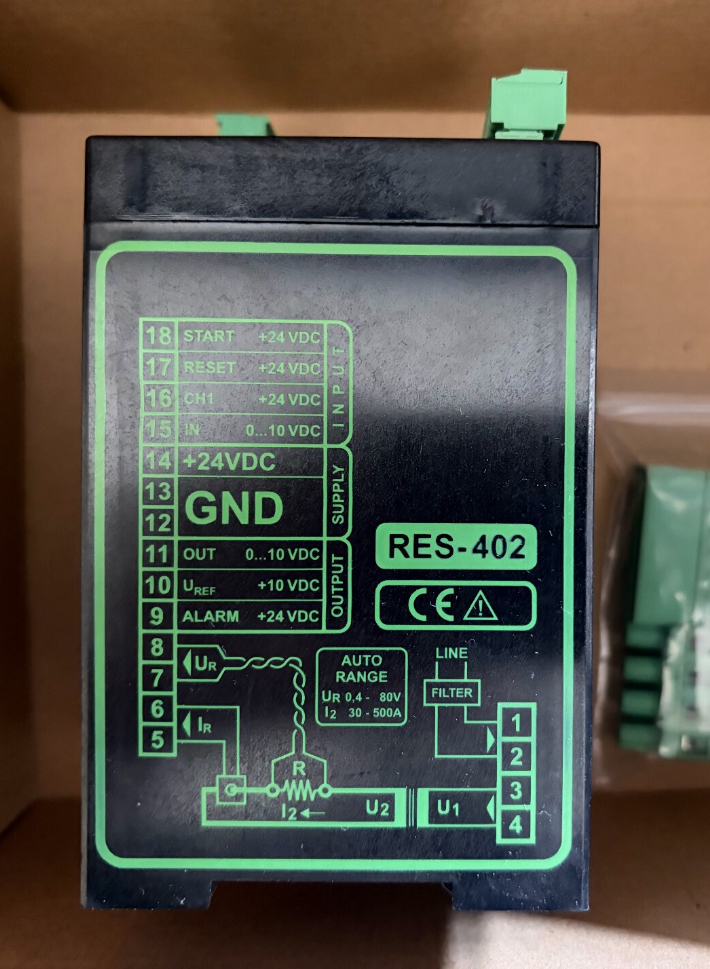

Marke: ROPEX, Deutschland
Product Definition: Sensorless resistive impulse heat-sealing Temperaturregler (No thermocouple required! Temperature is calculated by detecting resistance variation of the heat-sealing band itself.)
Anwendung: Control heat-sealing bands, sealing blades, hot cutting wires and thermal welding elements, widely adopted for impulse heat-sealing processes on bag-making machines and packaging equipment.
⚠️ Wichtiger Hinweis: RES-402 has been officially declared obsolete. Supplies mainly consist of new surplus stock and used refurbished units. Recommended upgraded alternatives: RES-420 / RES-430 / RES-5010.
- Model Coding & Order Number Breakdown
Full model format: RES-402/Supply Voltage
| Vollständiges Modell | Werks-Teilenummer. | Main Power Range |
| RES-402/115VAC | 740201 | 94~132 VAC |
| RES-402/230VAC | 740202 | 187~264 VAC (Standard for 220V mains in China) |
| RES-402/400VAC | 740203 | 323~456 VAC (For equipment powered by 380V mains) |
- Wichtige technische Spezifikationen
- Temperature Measurement Principle: Passive resistance detection (thermocouple-free)
- Temperature Measuring Range: 0~300 °C (Matched with A20 alloy heat-sealing band)
- Anpassung laden (AUTORANGE Auto-Ranging Function)
Transformer secondary voltage: 0.4~80 VAC
Secondary current: 30A~500A
- Montage: DIN TS35 standard rail mounting
Gesamtdimension: W90mm × D75mm × H135mm (einschließlich Terminals)
- Hilfsstromversorgung: 24VDC (Terminals 13/14), Max. 1A, Verpolungsschutz
(Must be powered independently and galvanically isolated from main power circuit)
- Kommunikation & Analog Interfaces (Electrically Isolated)
Setpoint input: 0~10VDC or external PD-3 potentiometer
Actual temperature output: 0~10 VDC (0–300℃ corresponds linearly to 0–10V, for PLC acquisition)
- Digital Control Signals (24VDC Isolated Input)
START (Heating enable), AUTOCAL (Automatic calibration), ZURÜCKSETZEN (Fehler-Reset)
- Grid Frequency Adaptation: Auto detection for 47~63Hz mains frequency
- Schutzfunktionen: Heat-sealing band breakage detection, overtemperature alarm, fault relay output with LED indicator
- Built-in Core Functions
AUTOCAL Automatic Zero Calibration: One-touch baseline resistance calibration after startup or heat band replacement
AUTOTUNE PID Self-Tuning: Automatically adapt to thermal capacity of heat-sealing bands to suppress temperature overshoot
AUTORANGE: Automatic detection of transformer secondary voltage and current; no manual DIP switch setting (Units manufactured from 2006 onwards)
Closed-loop primary-side phase-angle regulation for the transformer with low power loss
- Typische Anwendungsszenarien
Impulse heat sealing on plastic bag machines, vertical form-fill-seal machines and horizontal flow wrappers
Heat sealing for PE/PP composite films and aluminium foil pouches
Hot film cutting, thermal edge sealing and catheter heat-sealing processes
Heat-sealing stations for lithium-ion battery flexible packaging
- Verkabelungsrichtlinien (Condensed Version)
- Main Circuit LINE: Connect to AC main power as marked on the controller nameplate (115/230/400V)
- Terminals 13 & 14: Independent external 24VDC auxiliary power supply is mandatory (powers all signal circuits)
- The pulse transformer primary winding is driven by RES-402; secondary winding directly connects to the heat-sealing band
- Analog signals: 15(+) / 12(-) setpoint input; 11(+) / 12(-) actual temperature feedback output
- 16 START, 17 AUTOCAL, 18 ZURÜCKSETZEN: Triggered by 24VDC high level
- ALARM terminals: Passive fault output for PLC alarm signal collection
✅ Wiring Recommendation: Use twisted pair cables for secondary wiring of heat-sealing bands to reduce electromagnetic interference; reliably ground transformer secondary side to avoid electrostatic drift.
- Alternative Models for Obsolete Upgrade
- Direct functional replacement (Minimum modification required): RES-420
- Intelligent upgrade with fieldbus (Profinet/Modbus): RES-5010
- Ersatzhinweise: Versorgungsspannung überprüfen, transformer specifications and logic of PLC analog signals & digitale I/O.
- Schnelle Fehlerbehebung
- ALARM LED steady on, heating disabled: Broken heat-sealing band or open secondary circuit
- Persistently low temperature, unstable control: AUTOCAL not executed, insufficient transformer capacity
- Severe temperature oscillation and overshoot: Re-run AUTOTUNE self-tuning
- Controller completely unresponsive: Inspect independent 24VDC auxiliary power supply
(Common oversight! The unit cannot operate with main LINE power only.)
Detailed Explanation of AUTORANGE (Automatic Load Ranging Function) for ROPEX RES‑402
Critical Preliminary Clarification
AUTORANGE ≠ AUTOCAL
AUTORANGE: Detect transformer secondary voltage U₂ and secondary current I₂, automatically configure hardware measurement ranges (hardware gain matching)
AUTOCAL: Collect baseline resistance of cold heat-sealing band at ambient temperature, establish resistance ↔ temperature conversion curve (temperature zero calibration)
The two functions work collaboratively yet remain independent.
Production Version Boundary (Key Information for Procurement & Wartung)
- RES‑402 manufactured before December 2005: No AUTORANGE
Internal DIP switches must be manually adjusted to set secondary voltage and current ranges. Incorrect switch settings cause measurement failure and alarms.
- RES‑402 manufactured from January 2006 onwards: AUTORANGE equipped
DIP switch configuration is overridden by firmware. No manual range setup required. Load electrical parameters are automatically identified during AUTOCAL procedure.
- Official Definition of AUTORANGE
Vollständiger Name: Automatic configuration of secondary voltage and current ranges
Automatically detect secondary voltage U₂ and output current I₂ of pulse transformer, dynamically select internal voltage sampling circuit and current transformer amplification gain. This ensures measurement circuits operate within optimal accuracy range and enables wide load compatibility.
Official Rated Load Coverage (New Version)
Transformer secondary open-circuit / operating voltage U₂: 0.4 VAC ~ 80 VAC
Transformer secondary operating current I₂: 30 A ~ 500 A
Simplified explanation: A single RES‑402 unit can drive low-power narrow sealing bands (Niederspannung, tens of amperes) as well as wide, long high-power sealing blades (high voltage, hundreds of amperes). No controller replacement or internal switch adjustment needed.
- Underlying Operating Principle
RES‑402 is a thermocouple-free resistive impulse heat-sealing controller. Temperature is calculated continuously based on resistance variation of the heat-sealing band.
To accurately measure band resistance, the controller simultaneously samples two signals:
- Secondary voltage signal Ur of pulse transformer
- Secondary loop current signal Ir
Instantaneous resistance of the heat-sealing band is calculated via Ohm’s Law: R = Ur / Und.
Multiple sets of hardware voltage dividers and amplifier circuits are integrated internally. Different U₂/I₂ levels require matched amplification ranges.
AUTORANGE Execution Sequence & Timing
- Controller completes power-on self-test (Wait ≥10s)
- Confirm START signal is OFF and heat-sealing band cools down to ambient temperature
- User triggers AUTOCAL (Front panel button or 24VDC pulse on external terminal)
- AUTORANGE load scan activates simultaneously upon AUTOCAL startup
Controller sends low-level test excitation signal to transformer secondary circuit
Raw sampled amplitude of Ur and Ir is captured
MCU switches gain of internal analog front-end automatically to match measured U₂ & I₂
- After successful range matching, sampling parameters are locked; yellow AUTOCAL LED illuminates continuously
- Baseline resistance sampling completes (ca. 10~15s). Calibration finishes and ranging parameters are saved.
- The identified range parameters are applied for closed-loop temperature control in all subsequent heating cycles
⚠️ AUTORANGE only performs load scanning during AUTOCAL calibration. Dynamic range switching will NOT occur during normal heating operation.
AUTOCAL must be re-executed to refresh AUTORANGE load identification after replacing heat-sealing band, pulse transformer or modifying sealing strip length!
- Engineering Benefits of AUTORANGE (Comparison with Old Version with Manual DIP Switches)
| Anwendungsszenario | Older Units without AUTORANGE | Newer Units with AUTORANGE |
| Equipment redesign / heat blade replacement | Open controller housing and adjust DIP switches; high risk of misconfiguration | Execute AUTOCAL without disassembly for automatic adaptation |
| Common spare controller for multiple machine variants | Spare parts cannot be shared; inventory split by voltage/current range | Universal spare part with single model RES‑402 |
| Consequence of incorrect range setting | Temperaturdrift, unstable control, frequent ALARM, false band breakage detection | Automatic matching; eliminates human configuration error risk |
| On-site commissioning workload | Technicians must memorize DIP switch tables | Fewer electrical commissioning steps |
- Voraussetzungen & Limitations of AUTORANGE (Critical Know-how to Avoid Field Failures)
✅ Supported Operating Conditions
- Pulse transformer secondary voltage: Minimum 0.4VAC, maximum 80VAC
- Steady-state secondary operating current ≥30A; AUTORANGE fails and triggers alarms if current <30A (UR/IR signal error)
Narrow sealing strips with operating current below 30A represent the most frequent field pitfall!
- Unbroken secondary circuit; no open circuit or loose terminals on heat-sealing band
- Number of CT winding turns strictly follows ROPEX specifications
(Multiple primary turns through CT are recommended for current <100A to boost sampling signal amplitude)
❌ Parameters AUTORANGE CANNOT automatically adjust; Manual verification required
- Current transformer winding turns: AUTORANGE cannot detect CT turns; wrong turns lead to temperature reading deviation
- Mains frequency: Although 47–63Hz auto-adaptive, this function is independent from AUTORANGE
- Heat-sealing band material (A20 alloy etc.): Related to internal temperature characteristic curves, irrelevant to ranging
- Main supply voltage (115/230/400VAC): Determined by controller model; not processed by AUTORANGE
- Typical Fault Phenomena Rooted in AUTORANGE and Analysis
Controller Alarm: UR signal error / IR signal error (Red ALARM LED flashing)
- Transformer secondary voltage U₂<0.4V or>80VAC, exceeding AUTORANGE range limits
- Secondary operating current<30A, below minimum detection threshold
- Broken heat-sealing band, loose terminals or open secondary circuit → No valid sampling signal during AUTORANGE scanning
- Incorrect CT installation, wrong winding turns or damaged current transformer
- AUTOCAL initiated while the heat-sealing band remains hot; variable load impedance disrupts scanning
- Old hardware manufactured before 2005 (No AUTORANGE); operators mistakenly treat it as updated unit without setting DIP switches
- AUTORANGE Performance Comparison with Successor Models
- RES‑420: Enhanced AUTORANGE, secondary voltage range extended to 0.4~120VAC, identical current limits
- RES‑5010: Fully digital sampling, retains automatic load identification plus fieldbus communication capability
- Standard On-site Commissioning Procedure
- Vervollständigen Sie die gesamte Verkabelung; ensure heat-sealing band fully cools to room temperature
- Deactivate START heating signal
- Power on controller and wait at least 10 Sekunden
- Trigger AUTOCAL calibration (Front panel button or external terminal pulse)
- Confirm yellow AUTOCAL LED lights steadily for 10~15s then extinguishes → AUTORANGE scanning + zero calibration fully completed
- Run trial operation; verify stable temperature reading without alarms
Maintenance Rule: Re-run AUTOCAL to refresh AUTORANGE load parameters every time heat-sealing band, pulse transformer or sealing structure is modified!



NH42-63-318x560.png "Automatische Transferschalter vom Typ CHINT PC (ATS)NH42-63/4SZ")



