 contactor,cortacircuitos,sensor,Codificador,SOCIEDAD ANÓNIMA,Convertidor

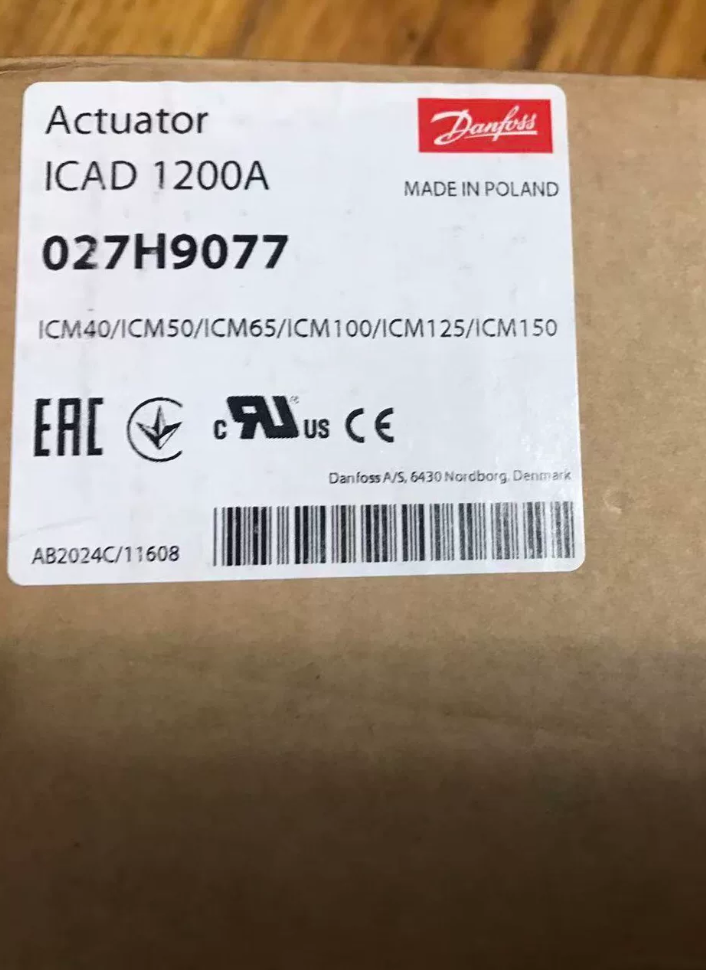
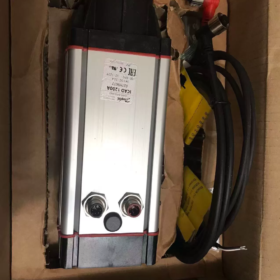
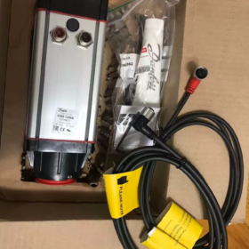
⚠️Important Note: El número de pieza 027H9075 corresponde a ICAD600A (NO ICAD1200A).
ICAD 1200A part-number: 027H9077, corriente nominal 2.0A.
027H9075: ICAD 600A, 24 VCC, rated 1.2 A, compatible with ICM20-32
027H9077: ICAD 1200A, 24 VCC, rated 2.0 A, compatible with ICM40-150
- Desglose del código del modelo
| Part‑number | Modelo | Fuente de alimentación | Corriente nominal | Compatible Valve Body |
| 027H9075 | ICAD 600A | 24 VCC | 1.2 A | ICM‑20/25/32 |
| 027H9077 | ICAD 1200A | 24 VCC | 2.0 A | ICM‑40…ICM‑150 |
ICAD = Stepper-motor actuator for ICM motor-operated valves; Version A: built-in encoder + local LCD MMI keypad.
- Parámetros eléctricos básicos (ICAD-1200A 027H9077, 24 V 2.0 A)
| Artículo | Especificación |
| Fuente de alimentación | 24 VDC isolated power supply; tolerance +10% /‑15% (21‑26.4 Vdc) |
| Consumo actual máximo | 2.0 A |
| Optional Fail‑Safe Power Supply | 24 VDC UPS / battery, 2.0 A |
| Analogue Input | 0/4‑20 mA (200 Oh); 0/2‑10 V (10 kΩ) |
| Salida analógica | 0/4‑20 mA, máximo. load 250 Ω |
| Entrada digital | Passive dry‑contact ON/OFF control |
| Salida digital | 3‑channel NPN open‑collector outputs (valve fully‑open, fully‑closed, alarma); external 5‑24 VDC required |
| Protección de ingreso | IP67 |
| Temperatura ambiente | ‑30 ℃~+50 ℃; condensación / icing conditions prohibited |
| Peso | Approx. 1.9 kg |
| Interfaces | 2 × M12 circular connectors: 4‑pin power, 8‑pin signal |
- Principio de funcionamiento
The ICAD uses a high-speed stepper motor with magnetic-coupling gear-free transmission to drive the ICM motor-operated valve. A built-in position encoder provides closed-loop valve-position feedback.
Supported functions:
- Continuous modulating via 4-20 mA / 2-10 V analogue signal.
- Digital dry-contact full-open / full-closed switching.
- Local LCD keypad for parameter setup, position indication and fault-code reading.
Magnetic-coupling design: No rigid mechanical connection between actuator and valve body; eliminates refrigerant-leakage risk.
- Asignación de pines: M12-8-pin Signal Connector
| Alfiler | Wire Colour | Función |
| 1 | Blanco | 24 V DC Positive |
| 2 | Marrón | 24 V DC Negative |
| 3 | Negro | Alarm Output NPN‑ |
| 4 | Marrón | Full‑Open Output NPN‑ |
| 5 | Rojo | Full‑Closed Output NPN‑ |
| 6 | Naranja | Signal GND |
| 7 | Amarillo | 4‑20 mA Input (+) |
| 8 | Verde | 2‑10 V Input / DI Digital Input (+) |
4-pin M12 power connector: Main 24 VDC supply; optional connection for fail-safe UPS power.
- Compatible Valve List
ICAD 600A (027H9075): ICM-20, ICM-25, ICM-32
ICAD 1200A (027H9077): ICM-40, 50, 65, 80, 100, 125, 150; also suitable for CVE pilot valves.
- Escenarios de aplicación típicos
refrigeración industrial, ammonia refrigeration, CO₂ transcritical refrigeration units
Liquid-line electronic expansion regulation
Suction-pressure / regulación de temperatura
Hot-gas bypass & hot-gas defrost control
Large cold-storage plants, refrigeration compressor stations, food-processing freezing lines
Errores de selección & Advertencias de riesgo
- Do not mix-up part-numbers: 027H9075 = 600A (1.2 A); 027H9077 = 1200A (2.0 A). Mechanical mounting interfaces are identical, but output torque differs drastically. Never drive large-size valves with ICAD-600A; this triggers A1 valve-mismatch alarm.
- Use isolated 24 VDC power supply only; 24 VAC is strictly forbidden. Calculate cable voltage drop; terminal voltage must not drop below 21 Vdc.
- Outputs are NPN transistors; external power supply is mandatory. Do NOT connect relay coils directly to actuator outputs.
- Rango de operación: -30 ℃ ~ +50 ℃. IP67 rating provides dustand splash-proof protection; permanent submersion is prohibited.
- Parameter i26 must be set to match the actual ICM valve type, otherwise alarm A1 will activate.
- Summary of Fault Codes
| Alarm Code | Descripción | Troubleshooting Guidance |
| A1 | Valve type not configured | Select correct ICM model in parameter i26 |
| A2 | Travel error / atasco mecánico | Check for valve jamming; verify magnetic‑coupling engagement |
| A3 | Supply‑voltage out‑of‑range | Check 24 V power supply and cable voltage drop |
| A4 | Fail‑safe supply fault | Unión Postal Universal / backup‑battery power supply abnormality |
- Información de reemplazo
ICAD600A / 1200A are mature active-range products, not obsolete. Legacy ICAD600 / 900 / 1200 can be directly replaced by A-series units; mechanical interfaces are fully compatible. Simply re-configure valve-type parameter i26 after swap-out.
Domestic alternative note: No drop-in magnetically-coupled replacement actuator available. Full valve-body + actuator assembly replacement is required for third-party retrofits.
Commissioning Procedure for danfoss ICAD 1200A (027H9077)
Applicable models: ICAD-600A / ICAD-1200A (A-series with LCD panel); 24 VDC supply; for ICM motor-operated valves.
⚠️027H9075 is ICAD-600A with reduced torque. Do NOT use it for ICM40 or larger valves.
Requisitos previos: Valve mechanically fitted, magnetic-coupling correctly engaged, piping pressure-test completed. All wiring performed with power removed; M12 connectors fully tightened.
- Pre-power-on Wiring Check (Obligatorio)
- Confirm isolated 24 VDC power supply; 24 VAC forbidden. Power-supply rating ≥ 2.5 A.
- Secure M12-4-pin power and M12-8-pin signal connectors. Cables undamaged; cable shield single-ended earthed.
- NPN output circuit: External 24 V must be supplied from PLC side. Never connect relay coils directly to actuator outputs.
- Analogue-signal circuit: Total loop impedance for 4-20 mA input ≤ 200 Ω. 2-10 V input impedance ≥ 10 kΩ.
- Verify valve stem free from mechanical obstruction. Magnetic-coupling ring correctly fitted, no disengagement.
- Power-up & Initial Self-test
- Apply 24 VDC supply; LCD illuminates and actuator performs automatic self-test.
- If alarm codes appear after self-test: record alarm code first, do not reset immediately.
- ⚠️First-time power-on: No valve selected, alarm A1 is normal expected behaviour.
- Basic Parameter Setup via LCD Keypad
- Enter menu: Press and hold OK key for 3 seconds.
- Locate parameter i26 Valve type
ICAD-1200A (ICM40-150): Select actual valve size (ICM-40 /50 /65 /80 /100 /125 /150).
ICAD-600A (027H9075): Only ICM-20-25-32 permitted.
- Save setting. Actuator executes full-stroke auto-calibration.
Behaviour: Actuator travels automatically to full-closed position, then full-open. Do not cut power or apply external force during calibration.
- When calibration completes, alarm A1 clears. If A1 persists: double-check i26 setting; inspect magnetic-coupling for slipping.
Frequently-used Parameter Table
| Parameter No. | Nombre del parámetro | Descripción | Configuración recomendada |
| i03 Control signal | Control source | 0 = Local manual; 1 = 4‑20 mA; 2 = 2‑10 V; 3 = Digital DI switch | Match control‑system hardware |
| i04 Min signal | Minimum control signal | 4 mA → 0 % position; 2 V → 0 % position | Factory default |
| i05 Max signal | Maximum control signal | 20 mA → 100 % position; 10 V → 100 % position | Factory default |
| i26 | Tipo de válvula | Must match physical ICM valve size | Select actual valve size on‑site |
| i40 Fail‑safe mode | Fail‑safe behaviour | 0 = No fail‑safe; 1 = Fail‑safe close; 2 = Fail‑safe open | Set according to process requirements |
| i50 Output function | Analogue output assignment | 0 = Valve‑position feedback | Default 0 |
- Functional Tests
4.1 Local Manual Mode Test
- Set i03 = `0 Local manual`.
- Use up/down keys to adjust valve position from 0 %-100 %.
- Compare LCD indicated position with actual valve movement.
No valve movement: Check magnetic-coupling, atasco mecánico, i26 misconfiguration.
- Drive valve to 0 % (full-closed) and 100 % (full-open); confirm mechanical end-stops are reached.
4.2 External Analogue-signal Control Test (SOCIEDAD ANÓNIMA / DCS)
- Set i03 to `1 (4-20 mA)` or `2 (2-10 V)` as appropriate.
- Send minimum signal (4 mA / 2 V) from PLC; confirm valve moves to 0 % full-closed.
- Send maximum signal (20 mA / 10 V); confirm valve moves to 100 % full-open.
- Send intermediate 50 % reference; verify position tracking. Read analogue feedback output for cross-validation.
4.3 Digital-output Verification (NPN outputs)
Monitor three NPN outputs via PLC:
Full-open output: Conducts at 100 % valve position.
Full-closed output: Conducts at 0 % valve position.
Alarm output: Conducts when actuator fault is active.
NPN logic: Conducted = pin short-circuited to GND; non-conducted = high-impedance state.
- Alarm Acknowledgement
- Transient alarms: Navigate to `Acknowledge alarm` menu item, press OK to confirm.
- Persistent alarms: Alarm recurs immediately after reset. Resolve root-cause fault before acknowledgement; avoid repeated blind resetting.
- Post-commissioning Final Steps
- Restore i03 to the control-source required by the plant-control system.
- Exit parameter menu to return to main position-display screen.
- Retighten M12 connectors; implement cable-strain-relief protection.
- Document commissioning data: i26 valve setting, i40 fail-safe mode for project records.
- On-site Troubleshooting Summary
| Síntoma de falla | Pasos para solucionar problemas |
| A1 Valve‑type not selected | 1. Verify i26 valve‑type setting; 2. Inspect magnetic‑coupling disengagement; 3. Confirm actuator‑valve mechanical mating |
| A2 Travel‑error mechanical fault | 1. Valve blocked by foreign objects; 2. Magnetic‑coupling slip; 3. Media icing; 4. Internal valve‑cartridge damage |
| A3 Power‑supply alarm | 1. Measure terminal voltage under load; voltage ≥ 21 V mandatory; 2. Inspect cable voltage drop / insufficient conductor cross‑section |
| Valve ignores control reference | 1. Wrong i03 source selection; 2. Broken signal wiring; 3. Faulty transmitter output; 4. Missing signal‑circuit common‑GND |
| Local manual works, external signal no response | Confirm i03 is NOT set to local manual; comprobar el cableado; verify signal‑loop impedance requirements |
- Commissioning Hard-Rules (Operaciones prohibidas)
- ❌ Hot-plug M12 connectors: Risk of IO-board electrostatic burnout.
- ❌ Operate actuator without configuring i26 valve-type: Magnetic-coupling damage risk.
- ❌ Use ICAD-600A (027H9075) for ICM40-and-larger valves: Insufficient torque causes recurring A2 and magnetic-coupling destruction.
- ❌ Power-loss during auto-calibration: Loss of stroke-calibration data.
- ❌ 24 VAC power supply: Permanent actuator power-supply-circuit destruction.
Fallos comunes & Troubleshooting for Danfoss ICAD-600A / ICAD-1200A (A-series LCD-type)
Applicable part-numbers: 027H9075 ICAD600A, 027H9077 ICAD1200A; 24 VDC supply, for ICM modulating valves.
Split into LCD-displayed alarm codes and non-alarming functional anomalies.
- Panel Alarm Codes (LCD Axx display)
| Alarm Code | Descripción de la falla | Root‑causes | Diagnóstico & Acción correctiva |
| A1 No valve selected | Valve‑type not configured / detection failure | 1. i26 not set on first commissioning | 1. Enter parameter i26, select matching ICM valve size, run auto‑calibration |
| 2. Magnetic‑coupling disengagement / poor mechanical mating | 2. Power‑off; check magnetic‑coupling ring seating; fasten actuator‑valve assembly | ||
| 3. Improper mounting | 3. Alarm clears after calibration; recurring A1 indicates worn / slipping magnetic‑coupling | ||
| A2 Travel error | Stroke over‑travel, atasco mecánico, torque deficiency | 1. Spool jamming, fouling, media icing | 1. Power‑off; manually verify free valve‑stem movement; remove ice / fouling |
| 2. Magnetic‑coupling slip / fracture | 2. Inspect magnetic‑coupling for wear; replace coupling kit if required | ||
| 3. ICAD‑600A driving oversized ICM40+ valves | 3. Torque matching rule: ICAD‑600A only for ICM20‑32; ICM40‑150 require ICAD‑1200A | ||
| 4. External force applied during calibration | 4. Re‑select i26 and perform full‑stroke calibration; no external force allowed during calibration | ||
| A3 Supply voltage | Supply voltage out‑of‑specification | 1. Power‑supply output outside 21‑26.4 VDC | 1. Measure M12 terminal voltage under load; must remain ≥ 21 VDC |
| 2. Long‑cable / thin‑conductor voltage‑drop under load | 2. Increase cable cross‑section; shorten cable run; power‑supply rating ≥ 2.5 A | ||
| 3. Insufficient power‑supply rating | 3. Use isolated DC power supply; ban 24 VAC | ||
| A4 Fail‑safe supply | Fail‑safe UPS / backup‑supply abnormality | 1. i40 fail‑safe mode enabled but no backup‑supply connected | 1. Fail‑safe not required: set i40 = 0 to disable fail‑safe function |
| 2. Backup‑supply wiring error, degraded battery | 2. When using fail‑safe: check backup‑24 V wiring and battery health | ||
| A5 Internal fault | Actuator internal PCB / motor hardware failure | Surge‑voltage damage, ESD / static‑electricity damage | 1. Power‑cycle attempt; persistent alarm = hardware failure; replace complete actuator |
| A6 Signal input error | External reference signal out‑of‑valid range | 1. 4‑20 mA < 3 mA or > 22 mA | 1. Measure PLC output signal to confirm valid range |
| 2. 2‑10 V < 1 V or > 11 V | 2. Check wiring and common‑GND; locate open‑circuit faults; verify i03 matches actual signal type | ||
| 3. Cableado roto, faulty signal source |
- Functional Abnormalities Without Active Alarms
Fault 1: Local manual works; external PLC reference has zero response
-Síntoma: Valve responds 0-100 % from keypad; no reaction to 4-20 mA / 2-10 V remote signal, no alarm.
-Root-causes:
- `i03 Control signal` set to 0 (local manual), remote reference blocked.
- Signal-type parameter mismatch (hardware 4-20 mA but i03 set for 2-10 V).
- Missing common-GND between signal source and actuator; floating signal.
- Broken signal cable, faulty PLC analogue channel.
-Acción correctiva:
- Set i03 to correct source: 1 = 4-20 mA; 2 = 2-10 V.
- Connect signal negative to actuator signal-GND (pin 6).
- Measure signal directly at actuator-side terminals with multimeter to isolate PLC-side versus actuator-side faults.
Fault 2: Reversed valve-position tracking; 4 mA = full-open, 20 mA = full-closed
-Root-cause: Reversed signal-span configuration.
-Acción correctiva: Swap numerical values of i04 minimum-signal and i05 maximum-signal; alternatively invert output scaling inside PLC program.
Fault 3: Chattering / hunting; valve moves intermittently, position oscillates
-Root-causes:
- High internal valve-spool friction, fouling / scaling.
- Voltage sag under load from undersized power-supply / alambrado.
- Electrical-noise interference; unshielded cables routed alongside power cables.
-Acción correctiva:
- Evaluate valve-body service; perform overhaul if fouled.
- Maintain terminal voltage ≥ 21 VDC under load; upgrade power-cable cross-section.
- Use shielded cable with single-end shield-earthing; separate signal wiring from power-cable routes.
Fault 4: No feedback from NPN digital outputs (full-open / full-closed / alarma)
-Síntoma: LCD indicates full-open status but PLC receives no feedback signal.
-Principio de funcionamiento: ICAD NPN open-collector outputs draw no voltage themselves; they only provide a switch-to-GND path.
-Root-causes:
- No external 24 V supply fed into PLC DI-input circuit.
- Mis-wiring; relay coil connected directly to output terminal.
- Incorrect output-threshold parameter settings.
-Acción correctiva:
- Supply external 24 V to PLC DI-channel; output pin pulls low to GND when active.
- Never drive relay coils directly; install intermediate relay.
Fault 5: No LCD illumination; actuator completely dead on power-up
-Root-causes:
- Zero 24 VDC supply; reversed power-supply polarity.
- Crimp-failure / bent pins inside M12 power connector.
- Surge-damage to internal power-supply circuit.
-Acción correctiva:
- Measure voltage and polarity at M12 power-connector terminals.
- Inspect connector pins for retraction / daño.
- Correct supply voltage present yet no display: falla interna del hardware, replace actuator.
- Frequent Human-induced Field Faults (Selección / Instalación / Commissioning-related)
- ICAD-600A (027H9075) driving ICM40-or-larger valves
Insufficient torque triggers repeated A2 travel-fault alarms and rapid magnetic-coupling wear. Must upgrade to ICAD-1200A (027H9077).
- Running unit without i26 valve-type configuration and auto-calibration
Incorrect stroke-data leads to incomplete valve-closure / incomplete opening; magnetic-coupling damage risk.
- Hot-swapping M12 circular connectors
ESD-stress may destroy IO-board electronics, triggering A5 internal-fault alarm.
- 24 VAC mains supply applied
Permanent destruction of actuator power-supply circuit, total unit loss.
- Power-interruption during auto-calibration
Calibration-stroke data lost; persistent A2 alarms; full recalibration required.
- Standardised General Troubleshooting Workflow
- Record LCD alarm-code; document operating conditions (temperatura, medio, valve-position).
- Apagado; inspect mechanical assembly: actuator mounting, magnetic-coupling, valve-spool jamming.
- Encendido; measure M12-terminal supply-voltage under load; confirm 21-26.4 VDC.
- Cross-check key parameters: i26 valve-type, i03 control-source, i40 fail-safe setting.
- Execute complete automatic valve-stroke calibration.
- Isolate fault-location by testing local manual mode:
✅ Local manual works: Fault lies in PLC, cabling or external control-system.
❌ Fault persists in local manual: Defect in actuator hardware, valve-body mechanics or magnetic-coupling.
Spare-part note: Magnetic-coupling ring is a consumable component and can be ordered separately; full-actuator replacement is not always required.





NH42-63-318x560.png "Interruptores de transferencia automática tipo PC CHINT (ATS)NH42-63/4SZ")



