

These are critical components ensuring the safe and stable operation of power transmission systems, mainly classified into six core categories: Conductor and Ground Wire Systems, Insulators, Fittings, Tower and Foundation Accessories, Lightning Protection & Overvoltage Protection, and Cable Accessories. A structured breakdown is provided below:
- Conductor and Ground Wire Systems (Core Transmission Components)
| Fitting Type | Función principal | Modelos comunes | Parámetros técnicos | Application Notes |
| Aluminum Conductor Steel Reinforced (ACSR) | Main power transmission, combining strength and conductivity | LGJ-300/40, LGJ-400/35, LGJ-500/45 | 220 kV lines typically use 2×300 mm² or 2×400 mm² bundled conductors; safety factor ≥ 2.5 | Corrosion-resistant types (p.ej., JL/G1A, JL/G2A) shall be selected per environment; high-strength ACSR for long spans |
| OPGW Optical Cable | Communication and line monitoring, doubles as ground wire | OPGW-24B1-80, OPGW-36B1-100 | Short‑circuit current withstand ≥ 25 kA/0.5 s; tensile strength ≥ 120 kN | Used with ground wires; splice closures must be waterproof and moisture‑proof; splicing loss ≤ 0.05 dB |
| Ordinary Ground Wire | Lightning protection, doubles as communication channel | JLB20A-80, JLB40-100 | Galvanized steel strand, cross‑section ≥ 70 mm² | Both ends must be reliably grounded; insulation clearance from phase conductors must be satisfied |
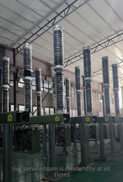
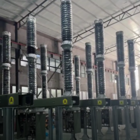
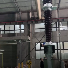
- Insulators (Core Insulation and Isolation)
220 kV line insulators fall into two main types: suspension insulators and post insulators.
Key parameters: dry arc distance ≥ 2020 milímetros, specific creepage distance ≥ 25 mm/kV (general areas)
| Material Type | Modelos comunes | Mechanical Load | Características | Suitable Scenarios |
| Composite Insulator | FXBW4-220/160, FXBW4-220/210 | 160 kN, 210 kN | Light (≈ 1/3 of porcelain), pollution‑flash resistant, maintenance‑free | Polluted areas, high‑altitude areas, long‑span sections |
| Porcelain Insulator | XP-160, XP-210 | 160 kN, 210 kN | Bajo costo, mature and reliable | Ordinary clean areas, plain areas |
| Glass Insulator | LXHY-160, LXHY-210 | 160 kN, 210 kN | Self‑destructs at zero value, easy to inspect | Lines requiring frequent inspection |
| Post Insulator | ZSW-220/8, ZSW-220/10 | 8 kN, 10 kN | Supports busbars and equipment connections | Substation outlets, both sides of circuit breakers |
- Power Fittings (Key Connection and Fixing Components)
Divided by function into clamps, connecting fittings, splicing fittings, and protection fittings, all complying with GB/T 2314‑2008.
1) Clamps (Core Conductor Fixing)
| Tipo | Modelos comunes | Suitable Conductors | Grip Requirement | Application Location |
| Suspension Clamp | XGU-4, XGU-5 | LGJ-300~630 mm² | ≥ 12% of conductor breaking strength | Straight towers, allows small conductor movement |
| Tension Clamp | NY-300/40, NY-400/35 | LGJ-300~630 mm² | ≥ 95% of conductor breaking strength | Tension towers, terminal towers, full tension bearing |
| Jumper Clamp | TJ-4, TJ-5 | Jumper connections | Contact resistance ≤ 1.2 μΩ | Jumper connections on both sides of tension towers |
2) Connecting and Splicing Fittings
| Tipo | Modelos comunes | Función | Technical Requirement |
| Socket Clevis | W-7A, W-10A | Connects insulator string to tower | Failure load ≥ 70 kN / 100 kN |
| Ball Eye | Q-7A, Q-10A | Connects insulator to fitting | Failure load ≥ 70 kN / 100 kN |
| Splicing Sleeve | JY-300/40, JY-400/35 | Conductor splicing | Resistance after crimping ≤ 1.1 × conductor resistance |
| Grading Ring | FJ-220 | Improves voltage distribution on insulators | Diameter 400–600 mm, installed at both ends of insulators |
3) Protection Fittings
| Tipo | Modelos comunes | Función | Suitable Conditions |
| Vibration Damper | FD-4, FD-5 | Suppresses aeolian vibration | Lines with span > 120 metro; installation spacing calculated |
| Spacer Damper | FG-4, FG-5 | Maintains bundled conductor spacing | 220 kV twin conductors, spacing 400 milímetros; 1 per 50–60 m |
| Corona Ring | FP-220 | Prevents corona discharge | High‑altitude, strong electric‑field areas |
- Tower and Foundation Accessories (Support Structure)
| Fitting Type | Modelos comunes | Función | Parámetros técnicos |
| Cross Arm | HD220-1, HD220-2 | Mounts insulators and fittings | Q235/Q345 steel, hot‑dip galvanized for corrosion protection |
| Hoop Clamp | BG-16, BG-18 | Fixes cross arms, ladders | Matches tower diameter; bolt strength ≥ 8.8 |
| Anchor Bolt | M30~M64 | Fixes tower foundation | Grade 45 steel, anti‑corrosion treated; tensile strength ≥ 600 MPa |
| Climbing Ladder | PT-220 | Access for tower maintenance | Step spacing 300 milímetros; handrail diameter 20 milímetros; load capacity ≥ 100 kilos |
- Lightning Protection and Overvoltage Protection Accessories
| Fitting Type | Modelos comunes | Función | Parámetros técnicos |
| Metal Oxide Arrester (MOA) | YH10WZ-204/532 | Limits lightning overvoltage | Tensión nominal 204 kV; residual voltage ≤ 532 kV; discharge capacity 20 kA/2 ms |
| Grounding Device | – | Discharges lightning current | Horizontal electrode: φ12 mm round steel; vertical electrode: 50×50 mm angle steel, L = 2.5 metro; grounding resistance ≤ 10 Ω |
| Line Fault Indicator | XJ-220 | Indicates short‑circuit/earth fault | Operating current: short‑circuit ≥ 100 A, earth ≥ 5 A; auto‑reset 1–24 h |
- Cable Accessories (For Cable Lines Only)
| Fitting Type | Modelos comunes | Función | Suitable Conditions |
| Cable Termination | WTY-220/1×1200 | Connects cable to overhead line/equipment | Cross‑section 400–2500 mm²; lightning impulse withstand voltage ≥ 950 kV |
| Joint | YJJJ-127/220 | Cable splicing | Waterproof rating IP68; operating temp −40~90 °C |
| Cross‑Bonding Grounding Box | NTJX-1 | Eliminates sheath induced voltage | 66–220 kV cables; equipped with sheath protector |
| Arrester Grounding Box | NTB-1 | Protects cable sheath | Built‑in MOA; tensión nominal 20 kV |
- Key Points for Selection and Application of 220 kV High‑Voltage Line Fittings
- Coincidencia de voltaje: Rated voltage of all fittings ≥ 252 kV (max operating voltage of 220 kV system)
- Mechanical Strength: Safety factor ≥ 2.5 (conductors, fittings); ≥ 3.0 (insulators)
- Adaptación ambiental:
Polluted areas: specific creepage distance ≥ 31 mm/kV; composite insulators preferred
Coastal areas: metal parts with hot‑dip galvanizing + passivation or 316L stainless steel for salt‑fog resistance
Cold areas: cold‑resistant materials (brittle temperature ≤ −40 °C); heavy‑duty vibration dampers
- Especificaciones de instalación:
Fitting contact surfaces: remove oxide film + apply conductive paste; contact resistance ≤ 1.2 μΩ
Insulator string: horizontal offset ≤ 150 milímetros; vertical deviation ≤ 50 milímetros
Conductor sag error ≤ ±5%; phase‑to‑phase sag difference ≤ 200 milímetros
- Main Brands and Alternative Models
| Fitting Category | Main Brands | Modelo recomendado | Alternative Model |
| Composite Insulator | Changyuan Gaoneng, Jinguan Electric | FXBW4-220/210 | FXBW-220/210 (Xi’an Porcelain) |
| Tension Clamp | China Electric Power Fittings Factory, Jiangsu Shenma | NY-400/35 | NLD-4 (bolt type, small section) |
| MOA | Xi’an XD, Henan Pinggao | YH10WZ-204/532 | YH10W-200/500 (general type) |
| Cable Termination | Taikai Cable, Changlan Electric | WTY-220/1×1200 | WTG-220 (dry termination) |
Selection of 220 kV high‑voltage line fittings must comprehensively consider voltage level, mechanical load, condiciones ambientales, and operational reliability. Key fittings shall pass State Grid Corporation qualification certification and comply with relevant GB and DL standards.
Below is a standardized bill of materials (BOM) para 220 kV overhead lines, directly usable for construction, quotation, and procurement, sorted by Straight Tower, Tension Tower, Terminal Tower + Cable Outlet.
Defaults:
Voltage: 220 kV (max operating voltage 252 kV)
Conductor: twin‑bundle ACSR LGJ‑400/35 (most commonly used)
Insulator: composite insulator (pollution‑resistant, maintenance‑free, mainstream choice)
- Standard BOM for 220 kV Single‑Circuit Straight Tower
Per tower (3 phases, twin‑bundle per phase)
| Artículo | Nombre | Model/Spec | Unit | Qty | Purpose |
| 1 | Composite Suspension Insulator String | FXBW4-220/160 | colocar | 3 | Suspension for 3hase conductors |
| 2 | Twin undle Suspension Clamp | XGS-5 | colocar | 6 | Suspension for 2 sub onductors per phase |
| 3 | Ball Eye | Q-10 | colocar | 6 | Connect insulator to clamp |
| 4 | Socket Clevis | W-10 | colocar | 6 | Connect insulator to cross arm |
| 5 | Twin undle Spacer | FG-400 (400 mm spacing) | pcs | As per span | Prevent galloping, maintain bundle spacing |
| 6 | Vibration Damper | FD-4 | colocar | 12 | 2 sets per phase for aeolian vibration control |
| 7 | Grading Ring | FJ-220 | colocar | 3 | Voltage grading at insulator ends, antiorona |
- Standard BOM for 220 kV Tension Tower (Angle / Junction)
Per tower (3 phases, twin‑bundle per phase)
| Artículo | Nombre | Model/Spec | Unit | Qty | Purpose |
| 1 | Composite Tension Insulator String | FXBW4-220/210 | colocar | 6 | 2 strings per phase (double suspension) |
| 2 | Twin‑Bundle Tension Clamp (crimp type) | NY-400/35 | colocar | 6 | Fix tension end of conductor |
| 3 | Twin‑Bundle Yoke Plate | L-12 | pcs | 3 | Converge twin‑bundle conductors |
| 4 | Jumper Clamp | TJ-5 | colocar | 6 | Jumper connection at tension tower |
| 5 | U‑Shackle | U-10 | colocar | 12 | Connect insulator to tower/clamp |
| 6 | Right‑Angle Plate | Z-10 | colocar | 12 | Directional connection |
| 7 | Grading & Corona Ring | FP-220 | colocar | 6 | Voltage grading and anti‑corona for tension strings |
| 8 | Vibration Damper | FD-4 | colocar | 12 | Vibration damping for jumpers/conductors |
- Fittings for 220 kV Terminal Tower → Substation Cable Outlet
Typical scheme: cable termination + arrester for GIS/main transformer connection
| Artículo | Nombre | Model/Spec | Unit | Qty | Purpose |
| 1 | 220 kV Outdoor Cable Termination | WTY-220/1×630~1200 mm² | colocar | 3 | Cable‑to‑overhead connection |
| 2 | Line MOA | YH10WZ-204/532 | fase | 3 | Limit lightning/switching overvoltage |
| 3 | Equipment Clamp (compression type) | SY-400 | colocar | 6 | Connect conductor to termination/arrester |
| 4 | Cable Fixing Fitting | 220 kV 3‑core/single‑core clamp | colocar | several | Cable fixing on tower |
| 5 | Grounding Flat Steel / Electrode | −50×5 hot‑dip galvanized | metro | per design | Grounding for arrester, cable sheath |
- General for Whole Line: Ground Wire & Lightning Grounding Accessories
Suitable for OPGW or ordinary ground wire
| Artículo | Nombre | Model/Spec | Unit | Purpose |
| 1 | Ground Wire Suspension Clamp | XD-8 | colocar | Straight suspension of ground wire |
| 2 | Ground Wire Tension Clamp | ND-8 | colocar | Tension fixing of ground wire |
| 3 | Down Ground Lead | φ12 hot‑dip galvanized round steel | metro | Tower grounding downlead |
| 4 | Vertical Ground Electrode | L50×50×5×2500 mm | pcs | Reduce grounding resistance |
| 5 | Grounding Clamp | JDX-8 | colocar | Connect ground wire to grounding system |

 Radiation Dosimeter")
 Servomotor Siemens")


")


NH42-63-318x560.png "Interruptores de transferencia automática tipo PC CHINT (ATS)NH42-63/4SZ")

")

