 contactor,cortacircuitos,inversor solar,medidor electrico,baterias solares

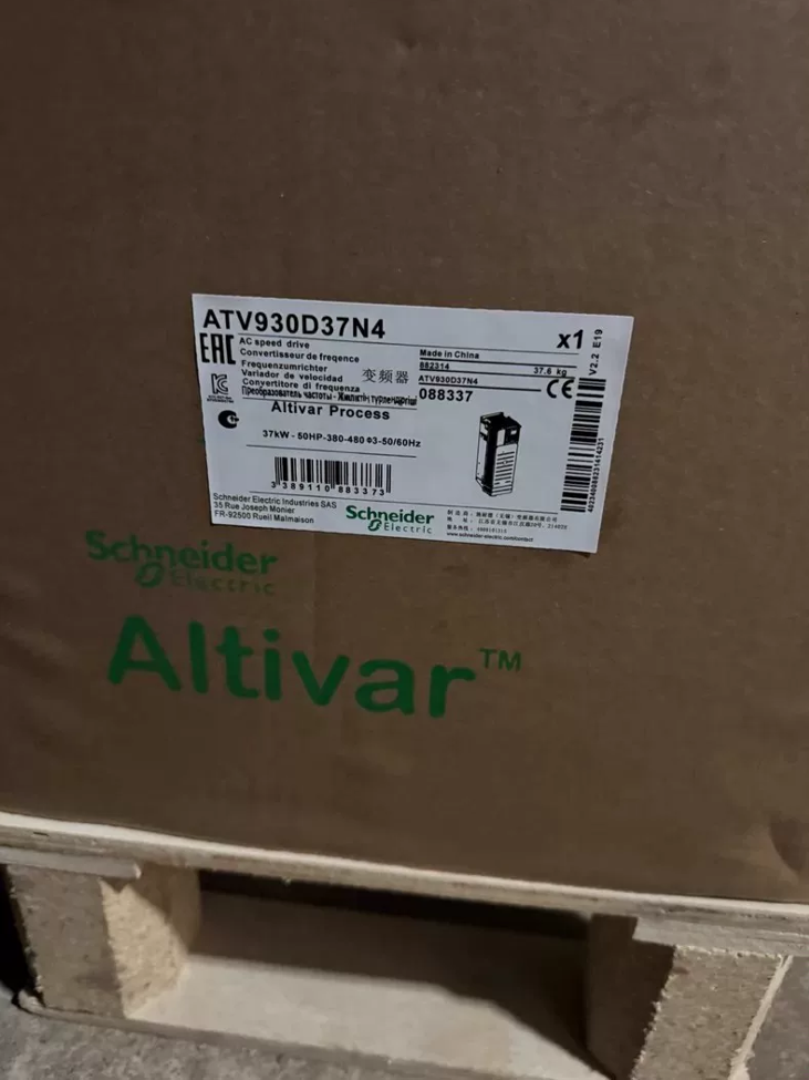

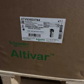
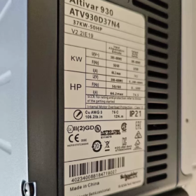
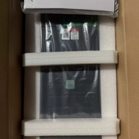

The ATV930D37N4 is a high-end standard variable speed drive from Electricidad Schneider’s Altivar Process ATV900 series, diseñado para industrias de procesos. Tiene una potencia nominal de servicio normal de 37kW y una potencia de servicio pesado de 30kW., compatible with 3-phase 380~480V power grids. It comes with an integrated braking chopper and EMC filter as standard, with an IP21 enclosure rating. Optimized for continuous operating conditions such as fans, bombas de agua, conveying systems, agitators and compressors, this unit integrates process PID, control de bombas múltiples, energy optimization and industrial fieldbus communication functions. It is widely used in water treatment, aceite & gas, alimento & bebida, minería, metallurgy and other industries, complying with international standards including IEC 61800 and UL 508C.
- Full Breakdown of Model Coding
Definition of Basic Model Markings
Canal de televisión británico 930 D37 N4
- Canal de televisión británico: Prefix for Altivar series, universal identifier for Schneider variable speed drives
- 930: Standard sub-series of the ATV900 Process range, positioned as a general-purpose drive for process industries, supporting asynchronous and synchronous motor control
- D37: Power rating code; matched to 37kW motors under Normal Duty and 30kW motors under Heavy Duty
- N4: Voltage and configuration class, representing 3-phase 380~480V AC input, 50/60Hz, built-in Class C2 EMC filter and standard integrated braking chopper
Extended Explanation of Full Model Suffixes
A typical complete order code is `ATV930D37N4Z`. Suffix letters indicate additional configurations:
Sin sufijo: Standard unit equipped with Chinese graphical display panel and integrated braking unit
z: Cost-optimized version with simplified operator panel
Specific letter suffixes correspond to dedicated firmware (for pump, fan and crane applications)
- Especificaciones técnicas básicas
- Parámetros de rendimiento eléctrico
| Elemento de parámetro | Valor de especificación | Observaciones |
| Voltaje de entrada nominal | 3-fase 380~480V CA, -15%~+10%, 50/60Hz±5% | Adaptable to wide-voltage power grids |
| Potencia de salida nominal (Servicio normal) | 37kilovatios (50caballos de fuerza) | For variable-torque / light constant-torque applications |
| Potencia de salida nominal (Servicio pesado) | 30kilovatios (40caballos de fuerza) | For heavy constant-torque and shock-load applications |
| Corriente de salida nominal (Servicio normal) | 74.5A (4frecuencia de conmutación kHz) | Nominal value under 400V grid |
| Corriente de salida nominal (Servicio pesado) | 61.5A (4frecuencia de conmutación kHz) | Nominal value under 400V grid |
| Capacidad de sobrecarga | Servicio normal: 120% rated current for 60s | Cycle length: 10 minutos |
| Servicio pesado: 150% rated current for 2s | ||
| Rango de frecuencia de salida | 0.01Hz ~ 599Hz | Adjustable via parameter settings |
| Modos de control | Control V/F, sensorless vector control, closed-loop vector control (encoder optional), synchronous motor control | Compatible with asynchronous, permanent magnet synchronous (PMSM) and synchronous reluctance (SynRM) motores |
| Ultimate Short-Circuit Breaking Capacity | Matched with 125A fuse, withstands 50kA short-circuit current | Coordination value for upstream protection |
| Funciones integradas | Braking chopper unit, Class C2 EMC filter, regulador PID, STO safety function | Standard integration, no extra options required |
- Mecánico & Parámetros físicos
Dimensiones generales (Ancho × Alto × Fondo): 271mm × 673mm × 226mm
Total weight: Aprox.. 28.2kilos
Enclosure rating: IP21 (CEI 60529) / UL Type 1, cabinet wall-mounted installation
Método de enfriamiento: Forced air cooling with intelligent variable-speed temperature-controlled fans
Tipo de montaje: Vertical wall mounting, allowable tilt ±10°
Temperatura ambiente de funcionamiento: -15°C ~ +50 °C (sin reducción); derating required for +50℃~+60℃
III. Funciones principales & Características técnicas
- Motor Control Performance
Universal drive support for asynchronous motors, Permanent Magnet Synchronous Motors (PMSM) and Synchronous Reluctance Motors (SynRM) without hardware replacement
Delivers 180% rated torque at 0.5Hz under sensorless vector mode for stable low-speed torque output
Standard motor auto-tuning function to automatically identify motor parameters and optimize control accuracy
Adjustable switching frequency from 2kHz to 16kHz to balance heat generation and motor noise
- Dedicated Process Industry Functions
Built-in high-precision PID regulator supporting closed-loop control of pressure, fluir, liquid level and temperature without external PLC
Multi-pump control function supporting up to 4 pumps for cyclic start/stop, fault switching and sleep/wake-up, suitable for constant-pressure water supply systems
Native flow compensation, sleep/wake and auto energy-saving modes, delivering 20%~40% comprehensive energy savings for fan and pump applications
Integrated fault recording and data log storage for the latest 10 fault records and operating waveforms to facilitate traceability analysis
- Seguridad & Funciones de protección
Standard STO (Desconexión de par segura) function achieving PL e / SIL 3 safety level to comply with machinery safety requirements
Full-range electrical protection: sobrecorriente, sobretensión, subtensión, output short-circuit, falla a tierra, motor overheating, drive overheating, output phase loss
Support for motor thermal protection model as an alternative to external thermal relays for precise motor temperature protection
- Comunicación & Expansion Capabilities
Standard communication interfaces: Modbus RTU (RS485), CANabierto
Expandable industrial fieldbuses: Profinet, Ethernet/IP, EtherCAT, Profibus DP, BACnet/IP, etc..
3 reserved expansion slots for I/O modules, encoder interface modules and communication modules
Built-in web server supporting remote monitoring, parameter configuration and fault diagnosis via web pages
- Instalación, Alambrado & Supporting Selection
- Main Circuit Cable Specifications (Copper Cable Reference)
Input power cable: Recommended 25mm² copper power cable
Output motor cable: Recommended 25mm² copper power cable; output reactor advised for long-distance wiring
Recommended braking resistor: Matched for 37kW model, 15Ω resistance with 5kW power rating
- Instalación & Precauciones de cableado
- Montaje vertical; reserve a minimum 100mm ventilation gap top and bottom, and 50mm clearance on left and right sides
- Separate power cables and control cables with a spacing ≥200mm to avoid electromagnetic interference
- Reliable earthing of ground terminals with earthing resistance ≤4Ω; single-end grounding for cable shields
- Par de apriete de terminales: 12~15N·m for main circuit terminals, 0.6~0.8N·m for control circuit terminals
- Common Fault Handling Matrix
| Código de falla | Fenómeno de falla | Root Cause Analysis | Soluciones paso a paso |
| OHF | Drive trips with overheating alarm | 1. Damaged cooling fan / blocked air duct | 1. Inspect fan operation and clear dust from air ducts |
| 2. Excessive ambient temperature | 2. Improve cabinet ventilation; operate under derating at high temperatures | ||
| 3. Long-term overload operation | 3. Check load current and adjust overload parameters | ||
| 4. Excessively high switching frequency setting | 4. Appropriately lower the switching frequency setting | ||
| SCF1 / SCF3 | Motor short-circuit / earth short-circuit fault | 1. Damaged insulation of output cables with phase-to-ground leakage | 1. Cut power and disconnect motor cables; measure insulation resistance of cables and motor |
| 2. Short-circuited motor windings / inter-turn short circuit | 2. Inspect motor terminals and terminal box for water ingress or burn marks | ||
| 3. Loose terminals with copper wire burrs causing short circuits | 3. Verify motor parameters match the nameplate and re-run auto-tuning | ||
| OCF | Overcurrent trip during operation | 1. Too short acceleration time leading to large startup inrush | 1. Extend acceleration time parameters and reduce startup torque boost value |
| 2. Sudden load variation or mechanical jamming | 2. Rotate motor by hand to check mechanical load and bearing jamming | ||
| 3. Malfunction of current detection components | 3. Disconnect load for no-load testing to troubleshoot hardware detection circuits | ||
| OVF | Overvoltage trip during deceleration | 1. Too short deceleration time and high load inertia | 1. Extend deceleration time and enable DC braking function |
| 2. Mismatched braking resistor resistance / cableado suelto | 2. Check braking resistor resistance and wiring; confirm braking unit is activated | ||
| 3. Excessively high grid voltage | 3. Monitor grid voltage; install input reactor if necessary | ||
| LF | Output phase loss alarm | 1. Open circuit on one phase of motor cable | 1. Test continuity of three phases of motor cable |
| 2. Poor contact from loose output terminals | 2. Tighten output terminals to specified torque | ||
| 3. Current unbalance caused by single-phase load | 3. Disable phase loss detection temporarily only for single-phase load commissioning (restore for formal operation) | ||
| Blank operator panel with no display after power-on | Operator panel remains dark and unresponsive after energization | 1. Input power phase loss / excessively low voltage | 1. Measure three-phase input voltage for normal values |
| 2. Internal switching power supply failure | 2. Cut power and re-plug operator panel connecting cable | ||
| 3. Loose operator panel cable causing poor contact | 3. Troubleshoot internal rectifier and switching power supply circuits |
- Power Model Comparison for the Same Series (ATV930 N4 Series, 380-480V)
| Modelo | Potencia de servicio normal | Potencia de servicio pesado | Corriente de salida nominal (Servicio normal) |
| ATV930D15N4 | 15kilovatios | 11kilovatios | 30.4A |
| ATV930D22N4 | 22kilovatios | 18.5kilovatios | 41.5A |
| ATV930D30N4 | 30kilovatios | 22kilovatios | 54.8A |
| ATV930D37N4 | 37kilovatios | 30kilovatios | 74.5A |
| ATV930D45N4 | 45kilovatios | 37kilovatios | 87A |
| ATV930D55N4 | 55kilovatios | 45kilovatios | 108A |
VII. Cross-Brand Equivalent Replacement Reference
| Marca | Modelo equivalente | Potencia nominal | Key Difference Description |
| TEJIDO | ACS880-01-072A-3 | 37kilovatios | Comparable functional positioning; different mounting dimensions and parameter architectures |
| siemens | 6SL3210-1PE27-5UL0 (G120) | 37kilovatios | Modular design with separate power unit and control unit; different cabinet compatibility |
| Innovación | MD500T37G | 37kilovatios | Cost-effective domestic alternative covering mainstream functions; non-interchangeable mounting dimensions |
Fallos comunes & Troubleshooting Solutions for Schneider ATV930D37N4
As an engineering-grade drive from Schneider’s Altivar Process range, on-site faults of the ATV930D37N4 mainly fall into four categories: carga coincidente, grid voltage fluctuation, heat dissipation conditions and parameter configuration. The inherent hardware failure rate of the unit itself is low. Below is a full summary of frequent on-site faults including official standard fault codes, fault phenomena, root cause analysis and step-by-step resolution procedures, compiled in accordance with Schneider official technical specifications and field maintenance practices.
- General Troubleshooting Matrix for High-Frequency Faults
- sobrecorriente & Short-Circuit Faults (Most Frequent On-Site; High-Voltage Circuit Inspection First)
| Código de falla | Fenómeno de falla | Root Cause Analysis | Soluciones paso a paso |
| SCF1 | Instant trip upon startup or operation with motor short-circuit prompt on panel | 1. Damaged insulation of output cables leading to phase-to-phase short circuit | 1. Do NOT repeatedly reset and force startup; cut power and disconnect motor-side cables |
| Motor Phase-to-Phase Short Circuit | 2. Inter-turn short circuit of motor windings and burnt terminal box | 2. Measure phase-to-phase and phase-to-earth insulation resistance of U/V/W with a megohmmeter; normal value ≥5MΩ | |
| 3. Loose terminals with copper burrs causing phase-to-phase arcing | 3. Inspect motor terminal box and terminal strip for burn marks and copper debris short-circuits | ||
| 4. Mismatched motor parameters and control mode resulting in excessive startup inrush | 4. Verify motor nameplate parameters, re-run motor auto-tuning and reduce torque boost magnitude | ||
| 5. If false alarms persist with normal insulation, lower switching frequency to 2~4kHz appropriately | |||
| SCF3 | Earth fault trip immediately after power-on startup with abnormal output earth detection | 1. Single-phase earth damage on output cables | 1. Disconnect motor cables and measure insulation of cables and motor to earth separately |
| Motor Earth Short Circuit | 2. Breakdown of motor winding insulation to earth | 2. Install output reactor for long-distance wiring to suppress earth leakage current | |
| 3. Excessive leakage current due to large distributed capacitance of long cables | 3. Appropriately raise earth fault detection threshold for multi-motor parallel applications | ||
| 4. Total leakage current exceeding threshold when multiple motors are connected in parallel | 4. Confirm standardized earthing system with reliable common earthing for drive and motor | ||
| OCF | Trip upon sudden load variation with steady-state current exceeding rated value | 1. Sudden mechanical load jamming or seized bearings | 1. Cut power and rotate motor by hand to check smoothness of motor and load mechanical transmission |
| Overcurrent During Operation | 2. Overly short acceleration time causing startup inrush exceeding rated value | 2. Extend acceleration time parameters and reduce startup torque boost coefficient | |
| 3. Mismatched vector control parameters leading to current loop oscillation | 3. Re-run static/dynamic motor auto-tuning to correct control parameters | ||
| 4. Verify load power and confirm if undersized model was selected for heavy-duty applications |
- Sobretensión, Subtensión & Braking Faults
| Código de falla | Fenómeno de falla | Root Cause Analysis | Soluciones paso a paso |
| OVF | Frequent trips during deceleration and shutdown with bus voltage exceeding 780V | 1. Overly short deceleration time, high load inertia and rapid energy feedback | 1. Extend deceleration time and enable DC braking function for auxiliary deceleration |
| DC Bus Overvoltage | 2. Disabled built-in braking unit or mismatched braking resistor resistance/power | 2. Confirm braking unit parameters are activated and verify braking resistor resistance (15/5kW recommended for 37kW model) | |
| 3. Excessively high grid input voltage elevating baseline bus voltage | 3. Check for loose braking resistor wiring and measure resistance for normal values | ||
| 4. Monitor grid input voltage; install input reactor if voltage is excessively high | |||
| FSU | Shutdown during grid fluctuations with bus voltage below threshold | 1. Aged contacts of upstream circuit breakers and contactors causing large contact voltage drop | 1. Measure three-phase input voltage to confirm if it drops below 320V (380sistema V) |
| Input Undervoltage | 2. Grid voltage dip and voltage drop from simultaneous startup of large-capacity equipment | 2. Check tightening torque of incoming terminals and inspect oxidation of upstream switch contacts | |
| 3. Damaged internal rectifier bridge or degraded bus capacitor capacitance | 3. If alarm persists under steady normal voltage, measure DC bus voltage and troubleshoot rectifier and capacitor circuits | ||
| NLP | Only control indicator lit on panel with no main circuit voltage display | 1. Only 24V control power connected without energized three-phase main circuit | 1. Check energization status of R/S/T three-phase main power supply |
| No Main Power Supply | 2. Phase loss on main circuit incoming lines or blown fuses | 2. Measure DC bus voltage between PA/+ and PC/- terminales; nominal value approx. 540V (380entrada V) | |
| 3. Malfunction of internal voltage detection circuit | 3. If alarm persists with normal bus voltage, internal detection hardware failure requiring after-sales maintenance | ||
| BRF | Trip during braking with abnormal braking circuit prompt | 1. Short-circuited braking resistor or excessive resistance deviation | 1. Cut power and measure braking resistor resistance to match nominal value |
| Braking Unit Fault | 2. Damaged built-in braking chopper IGBT | 2. Inspect braking resistor wiring for short circuits and loose connections | |
| 3. Excessively high braking current limit setting | 3. Replace braking unit or complete drive for hardware damage |
- Calentamiento excesivo & Overload Faults
| Código de falla | Fenómeno de falla | Root Cause Analysis | Soluciones paso a paso |
| OHF | Trip after a period of operation with heatsink temperature exceeding threshold | 1. Damaged cooling fan with insufficient speed and dust-blocked air ducts | 1. Inspect fan operation and clear dust from air ducts and heatsink |
| Drive Overheating | 2. Poor cabinet ventilation and ambient temperature over 50℃ | 2. Improve cabinet ventilation by installing cooling fans; operate under derating factor at high temperatures | |
| 3. Long-term overload operation and excessively high switching frequency setting | 3. Appropriately lower switching frequency to reduce module heat generation | ||
| 4. Poor contact between heatsink and power modules | 4. Allow temperature to drop naturally after fault clearance; restart via manual or auto reset | ||
| OLF | Motor overload prompt during operation with trip following inverse time curve | 1. Excessive load with continuous operating current exceeding motor rated value | 1. Monitor actual operating current and verify matching between load and motor power |
| Sobrecarga del motor | 2. Overly sensitive motor thermal protection parameter settings | 2. Adjust motor thermal protection curve to adapt to actual working conditions | |
| 3. Rising current caused by poor motor cooling and worn bearings | 3. Inspect motor cooling fan and bearing conditions to eliminate motor body faults | ||
| OTF | Shutdown triggered by external temperature sensor | 1. Excessive actual motor temperature rise and failed cooling system | 1. Inspect motor cooling system for blocked air ducts and damaged fans |
| Motor Overheating (PTC) | 2. Open or short-circuited PTC sensor wiring | 2. Measure resistance at PTC terminals to confirm intact sensor and wiring | |
| 3. Mismatched sensor type and parameter settings | 3. Verify matching between temperature protection parameter settings and sensor model |
- Control de motores & Load Faults
| Código de falla | Fenómeno de falla | Root Cause Analysis | Soluciones paso a paso |
| LF | Output phase loss alarm during startup or operation with severe three-phase current unbalance | 1. Open circuit on one phase of output cables and loose detached terminals | 1. Test continuity of three phases of motor cables and tighten output terminals |
| Pérdida de fase de salida | 2. Open circuit on one phase of motor windings | 2. Measure resistance of three-phase motor windings to rule out open circuits | |
| 3. Excessive current deviation caused by single-phase or special loads | 3. Temporarily disable phase loss detection only for special load commissioning; restore for formal operation | ||
| STF | Trip during low-speed operation with sustained high current | 1. Locked mechanical load and foreign object jamming transmission mechanism | 1. Cut power and rotate equipment by hand to locate mechanical jamming points and clean transmission mechanisms |
| Motor Stall | 2. Overly sensitive stall protection current and time parameters | 2. Verify stall protection parameters and appropriately relax stall current and time thresholds | |
| 3. Insufficient torque to drive heavy startup loads | 3. Increase torque boost value for heavy startup loads or select a higher-power model | ||
| ANF | Trip due to excessive speed deviation under closed-loop control | 1. Incorrect encoder wiring, signal interference and abnormal feedback | 1. Inspect encoder wiring and shield earthing to eliminate interference |
| Loss of Load Tracking | 2. Excessively high or low speed loop gain leading to system oscillation / slow response | 2. Adjust speed loop gain and integral time to optimize control parameters | |
| 3. Excessive load inertia and insufficient braking capacity | 3. Install braking resistor for high-inertia loads and extend acceleration/deceleration time | ||
| 4. Temporarily disable load tracking detection function for non-critical applications |
- Comunicación, Parámetro & Configuration Faults
| Código de falla | Fenómeno de falla | Root Cause Analysis | Soluciones paso a paso |
| ILF | Unrecognizable expansion modules (codificador, tarjetas de comunicacion) | 1. Loose insertion and poor contact of option cards | 1. Cut power and re-plug option cards to ensure fully seated and non-oxidized pins |
| Internal Option Card Communication Fault | 2. Incompatible module model with drive | 2. Verify module model compatibility with ATV930 series | |
| 3. Communication interruption caused by electromagnetic interference | 3. Strengthen shield earthing and route cables away from power lines | ||
| CFF | Alarm after hardware replacement with mismatched parameters and hardware | 1. Configuration not updated after replacing option cards or power boards | 1. Enter configuration menu and run automatic hardware identification |
| Configuration Mismatch | 2. Incompatible firmware version and hardware | 2. Upgrade drive firmware to matching version | |
| 3. Version mismatch during parameter backup restoration | 3. Restore factory settings and reconfigure parameters | ||
| EEF1/EEF2 | Parameters cannot be saved and lost after power-on | 1. Corrupted data on EEPROM memory chip | 1. Restore factory settings and re-enter parameters |
| Memory Fault | 2. Data disorder from frequent power cuts and voltage surges | 2. Replace control board if fault recurs repeatedly due to damaged memory chip hardware |
- Fuente de alimentación & Fallos de hardware
| Fenómeno de falla | Root Cause Analysis | Soluciones paso a paso |
| Blank operator panel with no display after power-on | 1. Phase loss on main circuit power supply and blown input fuses | 1. Measure three-phase input voltage to confirm no phase loss or open circuit on incoming lines |
| 2. Damaged internal switching power supply | 2. Cut power and re-plug operator panel connecting cable; test with spare panel | |
| 3. Loose operator panel cable and faulty panel itself | 3. Professional maintenance required for internal switching power supply failure with normal bus voltage | |
| Upstream circuit breaker trips immediately after power-on | 1. Input-side short circuit and breakdown of rectifier bridge | 1. Do NOT repeatedly energize unit; cut power and measure input-side insulation and IGBT continuity |
| 2. Short-circuit damage of IGBT power modules | 2. Inspect rectifier bridge, bus capacitors and IGBT modules for breakdown damage | |
| 3. Short-circuit breakdown of bus capacitors | 3. Return complete unit to factory or arrange professional maintenance for power hardware damage; disassembly of power circuits on site is prohibited |
- General Troubleshooting Procedures (Rapid On-Site Locating)
- Read fault codes first: Retrieve fault codes and frozen data including current, voltage and temperature at fault occurrence via the panel diagnostic menu to quickly identify fault categories.
- Inspect high-voltage circuits first: For overcurrent, short-circuit and overvoltage faults, cut power to inspect external cables, motors and power grids before checking the drive itself.
- Parameter verification: For nuisance trips and abnormal control performance, prioritize checking core configurations such as motor parameters, protection thresholds and acceleration/deceleration time; re-run auto-tuning if necessary.
- Hardware replacement verification: Adopt replacement testing for panel, communication and option card faults to quickly distinguish between unit failure and accessory defects.
III. Fault Prevention & Routine Maintenance Guidelines
- Clean dust from air ducts and heatsinks every quarter; inspect cooling fan operation annually and replace fans immediately upon abnormal noise.
- Retighten high-current terminals to rated torque once a year to avoid excessive contact resistance and heat generation.
- For first energization after long-term storage, preheat at low voltage to prevent damage from surge current to bus capacitors.
- Install input reactors for sites with severe grid voltage fluctuation; fit output reactors for long-distance motor wiring.
| ATV61H075N4Z | ATV61H075N4 | ATV71H075N4Z | ATV71H075N4 | ATV610U07N4 |
| ATV61HU15N4Z | ATV61HU15N4 | ATV71HU15N4Z | ATV71HU15N4 | ATV610U15N4 |
| ATV61HU22N4Z | ATV61HU22N4 | ATV71HU22N4Z | ATV71HU22N4 | ATV610U22N4 |
| ATV61HU30N4Z | ATV61HU30N4 | ATV71HU30N4Z | ATV71HU30N4 | ATV610U30N4 |
| ATV61HU40N4Z | ATV61HU40N4 | ATV71HU40N4Z | ATV71HU40N4 | ATV610U40N4 |
| ATV61HU55N4Z | ATV61HU55N4 | ATV71HU55N4Z | ATV71HU55N4 | ATV610U55N4 |
| ATV61HU75N4Z | ATV61HU75N4 | ATV71HU75N4Z | ATV71HU75N4 | ATV610U75N4 |
| ATV61HD11N4Z | ATV61HD11N4 | ATV71HD11N4Z | ATV71HD11N4 | ATV610D11N4 |
| ATV61HD15N4Z | ATV61HD15N4 | ATV71HD15N4Z | ATV71HD15N4 | ATV610D15N4 |
| ATV61HD18N4Z | ATV61HD18N4 | ATV71HD18N4Z | ATV71HD18N4 | ATV610D18N4 |
| ATV61HD22N4Z | ATV61HD22N4 | ATV71HD22N4Z | ATV71HD22N4 | ATV610D22N4 |
| ATV61HD30N4Z | ATV61HD30N4 | ATV71HD30N4Z | ATV71HD30N4 | ATV610D30N4 |
| ATV61HD37N4Z | ATV61HD37N4 | ATV71HD37N4Z | ATV71HD37N4 | ATV610D37N4 |
| ATV61HD45N4Z | ATV61HD45N4 | ATV71HD45N4Z | ATV71HD45N4 | ATV610D45N4 |
| ATV61HD55N4Z | ATV61HD55N4 | ATV71HD55N4Z | ATV71HD55N4 | ATV610D55N4 |
| ATV61HD75N4Z | ATV61HD75N4 | ATV71HD75N4Z | ATV71HD75N4 | ATV610D75N4 |
| ATV930U07N4 | ATV61HD90N4 | 90kilovatios | ATV71HD90N4 | ATV610D90N4 |
| ATV930U15N4 | ATV61HC11N4 | 110kilovatios | ATV71HC11N4 | ATV610C11N4 |
| ATV930U22N4 | ATV61HC13N4 | 130kilovatios | ATV71HC13N4 | ATV610C13N4 |
| ATV930U30N4 | ATV61HC16N4 | 160kilovatios | ATV71HC16N4 | ATV610C16N4 |
| ATV930U40N4 | ATV61HC22N4 | 220kilovatios | ATV71HC22N4 | ATV610C22N4 |
| ATV930U55N4 | ATV61HC25N4 | 250kilovatios | ATV71HC25N4 | ATV610C25N4 |
| ATV930U75N4 | ATV212H075N4 | ATV310H037N4A | ATV312H037N4 | ATV320U04N4B |
| ATV930D11N4 | ATV212HU15N4 | ATV310H055N4A | ATV312H055N4 | ATV320U06N4B |
| ATV930D15N4 | ATV212HU22N4 | ATV310H075N4A | ATV312H075N4 | ATV320U07N4B |
| ATV930D18N4 | ATV212HU30N4 | ATV310HU11N4A | ATV312HU11N4 | ATV320U11N4B |
| ATV930D22N4 | ATV212HU40N4 | ATV310HU15N4A | ATV312HU15N4 | ATV320U15N4B |
| ATV930D30N4 | ATV212HU55N4 | ATV310HU22N4A | ATV312HU22N4 | ATV320U22N4B |
| ATV930D37N4 | ATV212HU75N4 | ATV310HU30N4A | ATV312HU30N4 | ATV320U30N4B |
| ATV930D45N4 | ATV212HD11N4 | ATV310HU40N4A | ATV312HU40N4 | ATV320U40N4B |
| ATV930D55N4 | ATV212HD15N4 | ATV310HU55N4A | ATV312HU55N4 | ATV320U55N4B |
| ATV930D75N4 | ATV212HD18N4 | ATV310HU75N4A | ATV312HU75N4 | ATV320U75N4B |
| ATV930D90N4 | ATV212HD22N4 | ATV310HD11N4A | ATV312HD11N4 | ATV320D11N4B |
| ATV930C11N4 | ATV212HD30N4 | ATV310HD15N4A | ATV312HD15N4 | ATV320D15N4B |
| ATV930C13N4 | ATV212HD37N4 | ATV320U04N4C | ATV340D11N4E | ATV32HU11N4 |
| ATV930C16N4 | ATV212HD45N4 | ATV320U06N4C | ATV340D15N4E | ATV32HU15N4 |
| ATV930C22N4 | ATV212HD55N4 | ATV320U07N4C | ATV340D18N4E | ATV32HU22N4 |
| ATV930C25N4 | ATV212HD75N4 | ATV320U11N4C | ATV340D22N4E | ATV32HU30N4 |
| ATS22D17Q | ATS48D17Q | ATV320U15N4C | ATV340D30N4E | ATV32HU40N4 |
| ATS22D32Q | ATS48D32Q | ATV320U22N4C | ATV340D37N4E | ATV32HU55N4 |
| ATS22D47Q | ATS48D47Q | ATV320U30N4C | ATV340D45N4E | ATV32HU75N4 |
| ATS22D62Q | ATS48D62Q | ATV320U40N4C | ATV340D55N4E | ATV32HD11N4 |
| ATS22D75Q | ATS48D75Q | ATV320U55N4C | ATV340D75N4E | ATV32HD15N4 |
| ATS22D88Q | ATS48D88Q | ATV320U75N4C | ACS510-01-03A3-4 | ACS550-01-03A3-4 |
| ATS22C11Q | ATS48C11Q | ATV320D11N4C | ACS510-01-04A1-4 | ACS550-01-04A1-4 |
| ATS22C14Q | ATS48C14Q | ATV320D15N4C | ACS510-01-05A6-4 | ACS550-01-05A6-4 |
| ATS22C17Q | ATS48C17Q | ACS580-01-02A7-4 | ACS510-01-07A2-4 | ACS550-01-07A2-4 |
| ATS22C21Q | ATS48C21Q | ACS580-01-03A4-4 | ACS510-01-09A4-4 | ACS550-01-09A4-4 |
| ATS22C25Q | ATS48C25Q | ACS580-01-04A1-4 | ACS510-01-012A-4 | ACS550-01-012A-4 |
| ATS22C32Q | ATS48C32Q | ACS580-01-05A7-4 | ACS510-01-017A-4 | ACS550-01-017A-4 |
| ATS22C41Q | ATS48C41Q | ACS580-01-07A3-4 | ACS510-01-025A-4 | ACS550-01-025A-4 |
| ATS22C48Q | ATS48C48Q | ACS580-01-09A5-4 | ACS510-01-031A-4 | ACS550-01-031A-4 |
| ATS22C59Q | ATS48C59Q | ACS580-01-12A7-4 | ACS510-01-038A-4 | ACS550-01-038A-4 |
| ACS580-01-169A-4 | ATS48C66Q | ACS580-01-018A-4 | ACS510-01-046A-4 | ACS550-01-046A-4 |
| ACS580-01-206A-4 | ACS580-01-106A-4 | ACS580-01-026A-4 | ACS510-01-060A-4 | ACS550-01-060A-4 |
| ACS580-01-246A-4 | ACS580-01-145A-4 | ACS580-01-033A-4 | ACS510-01-072A-4 | ACS550-01-072A-4 |
| ACS580-01-293A-4 | ACS510-01-246A-4 | ACS580-01-039A-4 | ACS510-01-088A-4 | ACS550-01-088A-4 |
| ACS580-01-363A-4 | ACS510-01-290A-4 | ACS580-01-046A-4 | ACS510-01-125A-4 | ACS550-01-125A-4 |
| ACS580-01-430A-4 | ACS550-01-246A-4 | ACS580-01-062A-4 | ACS510-01-157A-4 | ACS550-01-157A-4 |
| ACS580-04-505A-4 | ACS550-01-290A-4 | ACS580-01-073A-4 | ACS510-01-180A-4 | ACS550-01-180A-4 |
| ACS580-04-585A-4 | ACS580-01-088A-4 | ACS510-01-195A-4 | ACS550-01-195A-4 |


 Impulse Heat-Sealing Temperature Controller")


")


NH42-63-318x560.png "Interruptores de transferencia automática tipo PC CHINT (ATS)NH42-63/4SZ")


