 contactor,cortacircuitos,sensor,Codificador,SOCIEDAD ANÓNIMA,Convertidor

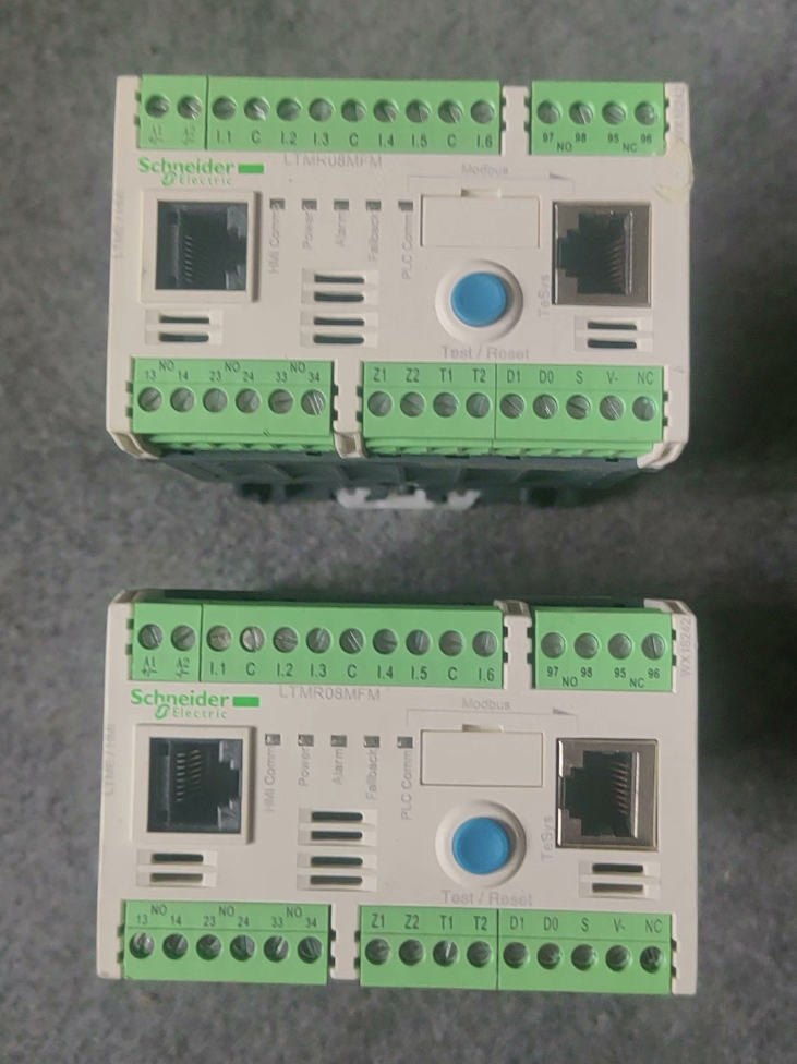

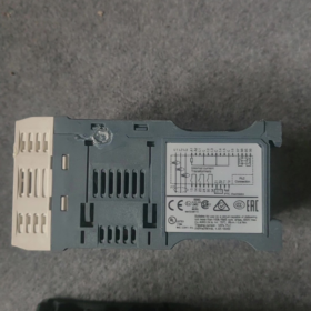
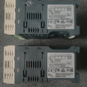
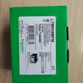
Schneider TeSys‑T (Serie LTMR) Controlador de gestión de motores: escenarios de aplicación
TeSys‑T es una protección de motor inteligente & unidad de monitoreo. Valores fundamentales: protección integral del motor + control lógico de E/S + Bus Modbus RTU para datos del motor & carga del registro de errores. Está dirigido a motores asíncronos trifásicos que requieren protección de grano fino., Monitoreo remoto y mantenimiento predictivo.. Se requiere un contactor externo para el arranque y parada del motor..
Estado del producto: Obsoleto planificado, Fecha de fin de vida útil: Sep 30, 2026
Serie: Unidad de gestión inteligente de motores TeSys‑T, Comunicación Modbus‑RS485, 0.4-Protección del circuito del motor 8A & escucha
- Desglose del código del modelo
| Campo | Código | Descripción |
| LTM | LTM | Serie de sistemas de gestión de motores TeSys‑T |
| R | R | Cuerpo del controlador |
| 8 | 8 | Rango de medición de corriente nominal 0,4‑8A |
| METRO | METRO | Comunicación: Modbus RTU (RS485) |
| F | F | Controlar el suministro: 100-240 VCA |
| METRO | METRO | Versión de terminal M (terminales estándar, 6DE / 3Salidas de relé DO) |
- Electricidad principal & Especificaciones de hardware
| Artículo | Valor |
| Rango de medición de corriente del motor | 0.4 … 8A |
| Tensión de alimentación de control | 100-240 VCA; tolerancia de funcionamiento: 93.5~264 VCA, 50/60 Hz |
| Entradas lógicas (DE) | 6Entradas lógicas tipo CA de canal; 0-40 V = estado APAGADO, 79-264V = estado ENCENDIDO |
| Salidas de relé (HACER) | 3NO + 1Relé de fallo NO+1NC; calificación de contacto: CA 250 V/5 A.; CC 30 V/5 A. |
| Interfaz de comunicación | Modbus-RTU RS485; doble RJ45 + puerto del bloque de terminales; tasa de baudios:1.2~19,2 kbit/s; rango de direcciones:1-247 |
| Dimensión general (Alto×Ancho×Profundidad) | 61 × 91 ×122,5 mm; peso:0.53 kilos; Montaje en carril DIN |
| Temperatura ambiente de funcionamiento | -20 ℃ … +60 ℃; temperatura de almacenamiento:-40℃~+85℃; Prohibida la condensación. |
| Tensión nominal de aislamiento Ui | 690 V; grado de contaminación3, categoría de sobretensión III |
| Par de cableado | 0.5-0,6 N·m; calibre de alambre:0.2-2,5 mm² sólido / cables flexibles |
III. Funciones de protección integradas
Protección de larga duración contra sobrecarga térmica, protección de rotor bloqueado, pérdida de fase, desequilibrio de fase, inversión de fase, protección contra fugas a tierra
Datos grabables: eventos de falla, corriente de arranque, contador de horas de funcionamiento, contexto del viaje, capacidad térmica residual; compatible con prealarma
Expansión: con módulo de expansión LTME para medición de voltaje, Protección contra factor de potencia y variación de carga.
- Principio operativo en profundidad
- Adquisición actual: Trifásico incorporado transformadores de corriente medida motor corriente RMS verdadera; detección integrada de corriente de defecto a tierra.
- modelo térmico: El algoritmo de memoria térmica del motor integrado simula el aumento de temperatura del motor para protección contra sobrecargas; retraso de enfriamiento aplicado después del disparo.
- Lógica de E/S: 6 Los DI reciben arranque/parada externos / comandos remotos locales; 3 salidas de relé accionan bobinas de contactor; El relé de falla proporciona una señal de alarma..
- Autobús Modbus: Subir actual, estado térmico, códigos de falla, estado de funcionamiento; Recibir comandos remotos de arranque y parada y modificación de parámetros..
- Pulsador local TEST/RESET azul: reinicio manual de fallas & prueba local; Indicadores LED del panel frontal (FUERZA / CORRER / ALARMA / FALLA).
Nota: Esta unidad sólo realiza protección & control lógico. El contactor del circuito principal debe estar cableado externamente para construir un circuito de arranque de motor completo..
- Definiciones de terminales clave (Resumen)
A1/A2: Fuente de alimentación del controlador, 100-240 VCA
C1‑C6: 6 canales de entrada lógica (DE)
21-24, 31-34: 3 SIN salidas de relé (para accionamiento por contactor)
95‑96‑97: Relé de fallo, 1NO+1NC
Modbus: RS485 de doble puerto (RJ45 + bloque de terminales), admite redes en cadena
- Mejora & Solución de reemplazo (Serie oficial de nueva generación TeSys‑Tera)
TeSys‑Tera adopta una arquitectura separada: cuerpo del controlador + sensores CT externos. La sustitución directa de hardware pin a pin frente a LTMR heredados no es factible; Se requiere modificación del cableado de detección de corriente..
| Esquema | Unidad principal | Sensor de corriente | Rango de corriente aplicable |
| Esquema1 | LTMTMFM (Modbus, 100-240 VCA/CC) | LTMTCTV3UT | 0.3-3A |
| Esquema2 | LTMTMFM (Modbus, 100-240 VCA/CC) | LTMTCTV25UT | 2.5-25A |
⚠ Riesgos de actualización:
- El antiguo LTMR integra CT interno; El nuevo Tera utiliza TC externa, Se requiere modificación del cableado del gabinete..
- Mapeo de registros Modbus & Los parámetros no son totalmente compatibles.; Modificación del programa PLC & la puesta en servicio es obligatoria.
- El diseño del terminal de E/S es completamente diferente; Se debe reelaborar el cableado secundario dentro del gabinete de control..
VII. Escenarios de aplicación típicos
Motores asíncronos trifásicos como bombas., fans, compresores y transportadores; tratamiento de agua, metalurgia, petróleo-gas, químico, industrias del cemento; Lazos de motor críticos que requieren acceso al bus basado en PLC para el estado de protección del motor y la lectura del registro de fallas..
VIII. Notas de selección & Condiciones de contorno
- Corriente de medición máxima 8A; No aplicable para motores con corriente nominal superior a 8A..
- Las DI son entradas de voltaje de CA, entradas no de contacto seco; Se requiere tensión de alimentación externa para el cierre de contactos..
- Frecuencia máxima de conmutación de salida de relé: 2 Hz; No apto para aplicaciones de ciclos de alta frecuencia..
- Se requiere protección a nivel de gabinete para ambientes corrosivos o propensos a la condensación..
- Fin de vida planificado: 30-sep-2026; Los diseños de nuevos proyectos adoptarán preferentemente TeSys-Tera..
- Equipos industriales de proceso general (Más común)
- Admirador & Circuitos de bomba
Bombas de circulación, bombas de enfriamiento, bombas de aguas residuales, bombas de agua de reposición, extractores de humos, ventiladores de suministro-retorno, ventiladores de torre de enfriamiento.
Valores: sobrecarga, rotor bloqueado, pérdida de fase & protección de falla a tierra; cargar corriente actual, estado de falla y tiempo de ejecución; Protección contra baja carga para evitar el funcionamiento en seco de la bomba..
Industrias: climatización, tratamiento de aguas residuales, abastecimiento, eurodiputado del edificio.
- Transportadores, alimentadores de cinta & alimentadores de tornillo
Cintas transportadoras, transportadores rascadores, alimentadores de tornillo, elevadores de cangilones.
Valores: viaje rápido por atasco mecánico; desequilibrio de fase & protección de falla a tierra; historial de fallos para el análisis de incidentes de atascos; soporte de lógica de enclavamiento.
Industrias: minería, materiales de construcción, almacenamiento de granos, manejo logístico, procesamiento químico.
- Compresores & unidades de refrigeración
Compresores de aire de tornillo, compresores de refrigeración, compresores de proceso.
Valores: evitar el rotor bloqueado / Sobrecarga causada por golpe de líquido.; protección del devanado modelo térmico; cargar el estado del motor al PLC / SCADA vía bus de campo.
- Tratamiento de agua & Industria Municipal (Implementación de TeSys‑T de gran volumen)
Bombas de elevación, bombas de retorno, motores agitadores para dosificación de químicos, sopladores de aireación, mamparas de barra, raspadores.
Características del sitio: Gran cantidad de motores distribuidos geográficamente.; monitoreo remoto de corriente & Fallos para reducir la inspección in situ.; alta incidencia de pérdida de fase & fallas de falla a tierra.
Arquitectura típica: Conexión en red multipunto Modbus-RTU con PLC, agregar datos de protección del motor al host SCADA.
- Químico & Industria Farmacéutica
Agitadores de reactores, bombas de circulación, bombas dosificadoras, bombas de transferencia de material, centrífugas.
Valores:
- Protección contra fugas a tierra que mitiga los daños al motor causados por fugas en los medios de proceso.
- Registro completo de eventos de fallas para la trazabilidad del proceso y el cumplimiento de GMP.
- Protección de inversión de fase para evitar la rotación inversa después del cambio de fase de mantenimiento.
Nota: El cuerpo del controlador no se puede instalar directamente en áreas explosivas peligrosas; recintos a prueba de explosiones / Se requieren contactores.
- Metalurgia, Cemento & Materiales de construcción
Ventiladores de eliminación de polvo, ventiladores de refrigeración, actuadores distribuidores, descargando unidades, pequeños motores de mesa de rodillos.
Condiciones de funcionamiento: carga de choque pesada, mucho polvo; rotor bloqueado frecuente & eventos de pérdida de fase; sobrecarga térmica combinada & El disparo rápido con rotor bloqueado protege los devanados del motor..
- Unidades auxiliares de plantas de energía
Pequeños motores auxiliares: ventiladores de refrigeración, bombas de aceite lubricante, bombas de agua sellada.
Valores: equipos auxiliares críticos; prealarma & Registro de instantáneas de fallas para el análisis de la causa raíz después de incidentes..
- Embalaje logístico & Maquinaria para Plásticos
Cintas transportadoras, agitadores, comederos, accionamientos auxiliares para extrusoras pequeñas.
Ventajas: local / selección de modo remoto a través de DI; La conducción de la bobina del contactor a través de DO elimina numerosos relés intermedios.
✅ Criterios de selección para TeSys‑T
Elija LTMR si se aplica alguna de las siguientes condiciones:
- Se requiere comunicación por bus de campo: leer actual, porcentaje de capacidad térmica, horas de funcionamiento, códigos de falla e instantáneas de fallas.
- Motores valiosos que requieren protección total: sobrecarga térmica, rotor bloqueado, pérdida de fase, desequilibrio de fase, inversión de fase, falla a tierra, subcarga.
- Modo de control dual local-remoto más lógica de enclavamiento compleja; reducir el recuento de relés intermedios.
- Requisito in situ para el registro de fallas para la resolución de problemas posteriores al evento.
- Red de monitoreo centralizada multimotor conectada a PLC / SCADA.
❌ Escenarios de aplicación inadecuados
- Solo se necesita protección de relé térmico simple sin comunicación ni registro de fallas: seleccione en su lugar relés de sobrecarga térmica LRD de bajo costo.
- La corriente de carga completa del motor supera con creces el rango CT integrado (LTMR CT integrado máximo:100 A). Utilice TeSys‑Tera de nueva generación con CT externo para motores de mayor corriente.
- Ciclismo de alta frecuencia: relé DO frecuencia de conmutación máxima 2 Hz; el desgaste de los contactos se acelerará.
- Zonas peligrosas intrínsecamente seguras: El cuerpo del controlador no se puede montar dentro de un área peligrosa..
- Protección de motor monofásico: TeSys‑T apunta a motores de inducción trifásicos.
📌 Resumen de la vieja generación y la nueva generación
Legado: serie LTMR (p.ej. LTMR08MFM), EOL previsto el 30 de septiembre de 2026, transformadores de corriente incorporados.
Nuevo: TeSys‑Tera (Serie LTMT), arquitectura CT externa, cobertura actual más amplia; preferido para la ingeniería de nuevos proyectos.
Principio de protección contra sobrecarga térmica de Schneider TeSys‑T (LTMR)
TeSys‑T no depende de la deformación física de la tira bimetálica como los relés térmicos convencionales. Implementa protección contra sobrecarga térmica mediante un modelo térmico electrónico. (algoritmo de memoria térmica del motor virtual) + Muestreo de corriente trifásica de verdadero valor eficaz.
- Etapa de adquisición de hardware
- Los transformadores de corriente trifásicos incorporados toman muestras de la corriente RMS real del estator (valores pico no simples).
- Circuito integrado de detección de corriente de falla a tierra.
- Las señales de corriente analógica son digitalizadas por MCU para una actualización periódica de la corriente de carga..
Para LTMR08MFM: rango de medición interno CT:0.4-8A para medición directa de corriente del bucle del estator.
- Centro: Modelo térmico de motor virtual (Memoria térmica)
El controlador ejecuta un modelo matemático que simula la acumulación y disipación de calor del devanado del motor.:
theta_{virtual} \propto \int(I^2 \cdot t)dt
Acumulación de calor: El porcentaje de capacidad térmica aumenta cuando la corriente de funcionamiento excede la corriente nominal del motor..
Disipación de calor: El porcentaje de capacidad térmica disminuye durante la parada o la operación con carga ligera., simulando el enfriamiento natural del motor.
Dos parámetros configurables clave impulsan el comportamiento del modelo:
- Corriente nominal del motor Ir: ajustar según la corriente de carga completa de la placa de identificación del motor.
- Clase de viaje (5/10/15/20/30), define características de disparo en tiempo inverso.
📌 Porcentaje de capacidad térmica: variable interna 0‑100%; El disparo por sobrecarga se activa al 100%.. Este valor se puede leer a través del registro Modbus..
Definición de clase de viaje
| Clase de viaje | Tiempo de viaje @7.2×Ir | Aplicación típica del motor |
| Clase 5 | 4-5s | Motores de arranque rápido |
| Clase 10 | 6-10s | Motores de inducción trifásicos estándar de uso general (más utilizado) |
| Clase 15 | 9-15 años | Aplicaciones de carga inicial de servicio pesado |
| Clase20 | 12-20 años | Motores de arranque pesado de alta inercia |
| Clase30 | 18-30 años | Cargas de alta inercia con tiempo de arranque prolongado (p.ej. grandes fans) |
- Manejo de sobrecarga para dos condiciones operativas típicas
① Sobrecarga de funcionamiento continuo (sobrecorriente persistente)
El motor funciona continuamente con I>Ir; La capacidad térmica virtual se acumula hasta alcanzar el 100%.. El controlador emite un comando de disparo., Desenergiza las salidas del relé de la bobina del contactor y detiene el motor.. Código de falla por sobrecarga más instantánea de la falla (3-corriente de fase & capacidad térmica en el instante del viaje) están almacenados.
② Sobrecarga durante el arranque del motor (corriente de irrupción de arranque de alta magnitud)
La clase de disparo configurada permite una corriente de arranque alta a corto plazo sin disparos molestos; El modelo térmico desintegra el calor acumulado una vez finalizado el arranque..
⚠ Característica crítica: Retención de memoria térmica
Después del viaje por sobrecarga, El valor de capacidad térmica virtual no se restablece inmediatamente incluso si la fuente de alimentación del controlador permanece activa.. Debe transcurrir el tiempo de enfriamiento simulado por el modelo o se requiere un RESET manual.
Caso práctico: después de viajes del motor por sobrecarga, los devanados permanecen calientes. Reinicio instantáneo & reiniciar corre el riesgo de quemar el motor. La memoria térmica evita el reinicio prematuro e imita el comportamiento de enfriamiento del motor real..
- Función de prealarma (Alerta temprana de sobrecarga)
Umbral de capacidad térmica configurable (p.ej. 80%). Cuando la capacidad térmica virtual supera el umbral, La prealarma de sobrecarga se activa sin dispararse.. La señal de advertencia se puede transmitir a través del relé DO o Modbus para mantenimiento predictivo antes de un apagado no planificado..
- Comparación: Relé térmico bimetálico convencional frente al modelo térmico electrónico TeSys‑T LTMR
| Artículo | Relé térmico bimetálico tradicional LRD | Protección contra sobrecarga del modelo térmico electrónico TeSys‑T LTMR |
| Principio de protección | Deformación térmica física de la tira bimetálica | Modelo térmico virtual basado en software con muestreo de corriente RMS |
| Característica de memoria térmica | El calor desaparece tras un corte de energía; sin retención térmica | La memoria térmica se puede conservar en caso de corte de energía. (configurable) |
| Influencia de la temperatura ambiente | Gabinete resistente que depende de la temperatura, desviación notable | Compensación de temperatura por software; baja sensibilidad a la temperatura ambiental |
| Configuración de clase de viaje | Fijado (modelos limitados admiten ajuste) | Clase 5‑30 configurable por software |
| Disponibilidad de datos | Sin salida de estado | Capacidad térmica legible por bus, instantáneas de fallas, mediciones actuales |
- Condiciones de contorno & Limitaciones
- La protección contra sobrecarga protege la acumulación térmica del devanado del motor., no cables de alimentación; Se requiere un disyuntor separado para la protección del conductor del cable..
- Pérdida de fase / El desequilibrio de fase acelera la acumulación del modelo térmico y avanza el umbral de disparo..
- El rotor bloqueado y la falla a tierra son funciones de protección independientes, no forma parte de la lógica de sobrecarga.
- Ajuste la clase de disparo si la condición real de enfriamiento del motor se desvía del modelo interno (p.ej. motor refrigerado por aire forzado).
- El modelo térmico LTMR está diseñado para motores de inducción trifásicos estándar.. La reutilización directa para motores alimentados por VFD o para fines especiales no es válida; el ajuste de parámetros es obligatorio.
- Lógica de restablecimiento de fallas
- Restablecimiento automático: habilitado para parámetros; El reinicio se produce solo después de que el modelo térmico se enfríe hasta un nivel de capacidad térmica seguro..
- Reinicio manual: Botón RESET del panel frontal local, Señal de reinicio del terminal IN, o comando de reinicio Modbus‑bus.
Operación prohibida: reinicios forzados repetidos antes de que el motor se enfríe después del disparo térmico.
- Código de falla
Código de falla de disparo por sobrecarga térmica: Juegos Olímpicos1. El registro de fallas almacena la marca de tiempo, porcentaje de corriente trifásica y capacidad térmica, recuperable vía Modbus.



NH42-63-318x560.png "Interruptores de transferencia automática tipo PC CHINT (ATS)NH42-63/4SZ")



