 contactor,cortacircuitos,sensor,Codificador,SOCIEDAD ANÓNIMA,Convertidor

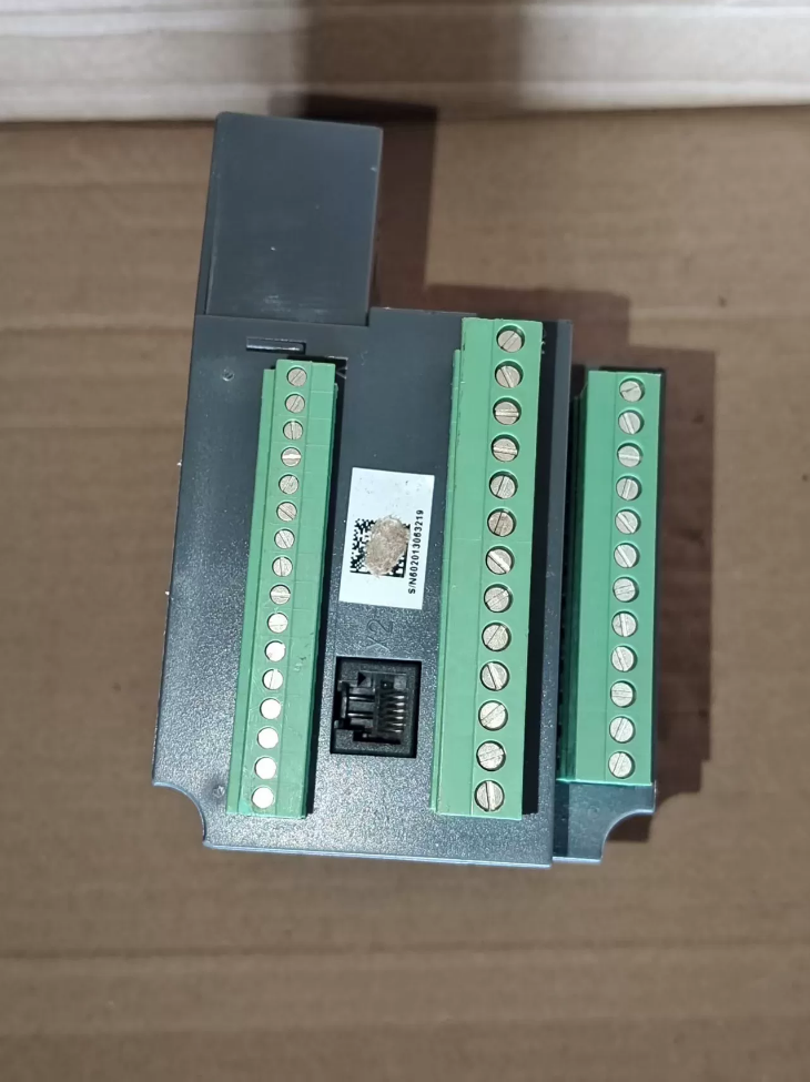

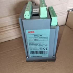
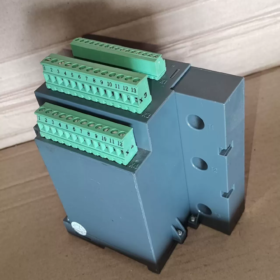
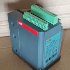
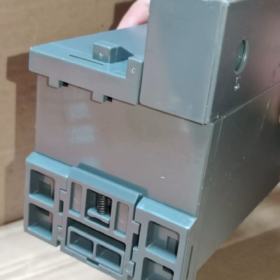
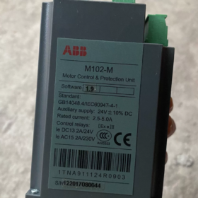
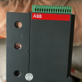
M10xseries advanced intelligent motor protection unit; M stands for ModbusRTU (RS485) communication version; the counterpart P refers to ProfibusDP version.
- Desglose del código del modelo
| Campo | Definición |
| M102 | Advanced type; supports current & voltage measurement, PTC, earth‑fault leakage, reversing and soft‑starter control; compared with M101 (current‑only, sin medición de voltaje) |
| ‑M | Interfaz de comunicación: Modbus RTU RS485, slave mode |
| Rango actual | 0.24‑1.0A / 1.0‑2.5A / 2.5‑5.0A / 5‑12.5A /12.5‑30A /30‑63A; external CT required for currents >63A |
| Fuente de alimentación | 24 VCC / 110 VAC / 240 VAC |
| MD21/MD31 | Local operator panel; MD21 full‑feature panel, MD31 compact panel; panels are optional accessories, main unit can be ordered without panel |
Example Ordering Code: `1TNA920611R0002` → M102M 24VDC, builtin CT 0.2463A, panel not included.
- Hardware central & Especificaciones eléctricas
| Artículo | Parámetro |
| Medición | 3-corriente de fase, 3‑phase voltage, fuerza, factor de potencia, corriente de fuga (external RCT required), PTC thermistor motor winding temperature measurement |
| Built‑in CT range | 0.24‑63A; external current transformer (secondary 1A/5A) is mandatory above 63A |
| Funciones de protección | Sobrecarga, rotor bloqueado, cortocircuito, pérdida de fase, desequilibrio de fase, over‑voltage, under‑voltage, voltage loss, PTC over‑temperature, earth‑fault leakage; configurable modes: alarm‑only / delayed trip / viaje instantáneo |
| Motor control modes | DOL direct‑on‑line, REV‑DOL reversing, soft‑starter interlock, star‑delta; M101 lacks voltage measurement and soft‑starter interlock capability |
| Comunicación | RS485 Modbus‑RTU; default baud‑rate 38400, Incluso paridad, 1 bit de parada; dirección 1‑247; máximo. 32 nodes per segment, total bus length ≤1200 m; 120 Ω terminating resistor required at bus ends |
| TRAVESURA | X1 digital inputs; X4 contactor‑control relay outputs, AC‑15 240V 2A; supports external push‑buttons and interlock signals |
| Montaje | DIN‑35 rail mounting; screw‑fixing also available; core motor‑management device for MNS switchgear cabinets |
| Condiciones ambientales | Temperatura de funcionamiento:‑20~+60℃; storage‑40~+85℃; condensation forbidden; unit IP20 |
III. Terminal Interface Definition (Llave)
X1: Entrada digital DI, PTC motor thermistor input
X2: MD operatorpanel interface (for MD21 / MD31)
X3: ModbusRTU RS485 communication, RCT leakagecurrent transformer, 3phase voltage acquisition inputs
X4: Contactorcontrol relay outputs (CCA/CCB/CCC), driving maincircuit contactor coils
⚠️Hardrule warning: Never connect highpower motor maincircuit current to voltagesampling terminals; PTC terminals shall not be connected to ordinary thermocouples; RS485 bus must adopt daisychain topology, La topología en estrella está prohibida.; 120 Ω terminating resistors must be fitted at bus ends.
- Software de soporte
- MCUsetup (MNavigate): PCbased parameter configuration, fault reading, trend logging; connected via USBRS485 adapter; parameter file import/export supported; GSD file available for hostsystem configuration.
- MD21 / MD31 operator panels: local parameter editing, reading running current/voltage and fault logs. Panels are ordered separately, not supplied with main unit.
- Package Contents Distinction
✅ Standard package (main unit only)
M102M main unit, rail mounting clips, paper user manual
❌ Not included in standard scope — must be ordered separately
MD21 / MD31 operator panel
1.2 m panel connecting cable
RCT residualcurrent leakage transformer
External current transformers (for circuits >63A)
RS485 communication cable, terminating resistors
- Protección & Fault Types
Faults are classified into Alarm (warning without tripping) and Trip (contactor deenergized). Fault records are stored in device memory and accessible via panel or fieldbus.
- Sobrecarga (thermalmodel motor heat accumulation protection)
- Lockedrotor (stall during startup or running)
- Shortcircuit (instant highcurrent fault)
- Pérdida de fase, 3phase current unbalance
- Sobretensión / subtensión / voltage loss (not available on M101)
- PTC overtemperature (motor winding temperature)
- Earthfault leakage (external RCT required)
Métodos de restablecimiento de fallas: local panel reset, DIterminal external reset, remote Modbus reset command.
VII. Errores de selección & Inapplicable Conditions
- M102M requires 3phase voltage sampling wiring to activate over/undervoltage protections; voltagerelated protections become fully disabled if only current is wired.
- For circuits >63 A, builtin CT cannot be used; external CT shall be adopted with correct secondary range (5A secondary → select 2.55A unit range; 1A secondary → select 0.51A unit range).
- For cabinets with heavy vibration or corrosive atmosphere, shockabsorbing brackets are recommended. Unit is IP20 and must not be installed outdoors.
- Communication network must use daisychain wiring; star topology forbidden; fit terminating resistors at both bus ends to avoid packet loss and communication errors.
- Comparison vs M101M: M101 has no voltage measurement, PTC temperature sensing, protección contra fugas, reversing or softstarter interlock. M101 is acceptable for simple fans; zapatillas, compressors and processcritical motors shall adopt M102M.
VIII. Crossbrand Alternative Reference
| TEJIDO M102‑M | Solución alternativa | Observaciones |
| M102‑M (Modbus) | Siemens 3UF7 (SIMOCODE pro) | Funcionalmente equivalente; hardware & software incompatible; full rewiring & re‑configuration required |
| Schneider LTMR series | Motor‑management relay with Modbus RTU, full function coverage; terminals and firmware cannot be reused directly |
M10x series is not formally discontinued, yet sparepart leadtime is extended. For drawercabinet retrofits, cabinet/drawer hardware can be retained; replace the unit and redownload motor parameters.
- Escenarios típicos de aplicaciones industriales
MNS lowvoltage drawertype switchgear in cement, acero, chemical and papermaking plants
Intelligent protection for process pumps, compresores, belt conveyors and fan motors
DCS / PLC collects fullscale motor operating and fault data via ModbusRTU to implement motormanagement system.
- Version Notes
M102M is available in 24VDC, 110VAC and 240VAC powersupply variants. Digitalinput DI power follows mainunit supply voltage. When ordering, confirm powersupply voltage, current range and requirement for MD panel.
ABB M102M Complete Installation Instructions
M102M installation consists of mainunit mounting and MD21/MD31 doormount operatorpanel installation. Main unit IP20; installation inside enclosed switch cabinets only; outdoor direct exposure prohibited.
- Unidad principal (M102M Body)
- Two mounting options
1)DIN35 (TS35×15) standard rail mounting [Recomendado, preferred for MNS drawer cabinets]
Unit has integrated spring clips at bottom for clipping onto 35 mm standard electrical rail. Montaje horizontal (terminals downward) is official preferred orientation.
Procedimiento de instalación: hook upper edge onto rail, press down unit until clip clicks into locked position. Eliminación: depress bottom clip and lift unit upwards.
Dimensiones generales: W110 mm × H140 mm × D75 mm.
2)Screwfastened direct mounting (no rail available)
Predrilled mounting holes on housing for M4 screw fixing to cabinet backplate.
⚠️Constraints: 90° vertical upright mounting (terminals facing left/right) esta permitido. Inverted mounting (terminals upward) is strictly forbidden: inversion degrades heat dissipation and impairs builtin CT measurement accuracy.
- Cabinetmount clearance & heatdissipation requirements
Maintain minimum 10 mm clearance top, bottom and both sides. Do not mount adjacent to heatgenerating components such as contactors, thermal relays or softstarters.
Operating ambient temperature20℃ ~ +60℃. If cabinet internal temperature exceeds 60℃, enhanced ventilation is mandatory to prevent derating and spurious protection trips.
Condensation must be avoided. Dehumidifier is recommended for highhumidity cabinets.
Fit rail endstops at both ends of DIN rail to prevent unit sliding.
- Par de apriete de terminales
Recommended screw torque: 0.81.0 Nuevo Méjico. Insufficient torque causes overheating; excessive torque damages terminal base.
Max single conductor crosssection: 10 mm²; maximum two identicalgauge conductors per terminal.
✔ Permitted mounting orientations
✔ Horizontal (terminals down, estándar)
✔ 90° vertical upright (terminals left / bien)
❌ Strictly forbidden
❌ Inverted (terminals upward)
❌ Tilt ±15°
- MD21 / MD31 Cabinetdoormount Operator Panels (Opcional, ordenado por separado)
Panels are fitted on switchcabinet / drawer door; connected to mainunit X2 port by dedicated TA201 RJ11 cable. Max cable length 2.5 m; cable extension or homemade substitute not allowed.
| Panel Model | Door Cut‑out Dimension (Ancho×Alto) | Panel Ingress Protection | Descripción |
| MD21 (Large LCD) | 84 mm × 68 mm | IP54 | Full‑feature LCD display, complete parameter setting & fault viewing |
| MD31 (Compacto) | 84 mm × 46 mm | IP54 | Indicator‑only unit without LCD; supports reset & start/stop; cannot modify full parameter set |
Pasos de instalación:
- Cut cabinet door according to cutout dimensions.
- Insert panel from outer side of door into cutout aperture.
- Fit rear mounting clamps and tighten locking tabs.
- Plug one end of dedicated RJ11 TA201 cable into panel, the other into mainunit X2.
⚠️Hardrule warnings:
- Ordinary telephonecable shall never replace original TAseries cable: it causes communication garbling or panel dropout.
- Avoid parallel routing alongside highpower power cables.
- Maximum cable length 2.5 m; extension prohibited.
III. RS485 (ModbusRTU) Communication Wiring Rules
M102M Modbus interface is located at terminal block X3.
- Wiring topology: strict daisychain series connection; estrella / tree topology prohibited.
- Fit external 120 Ω terminating resistor at both physical ends of bus. M102M has no internal terminating resistor.
- Use shielded twistedpair communication cable; shield grounded at cabinet masterend only, remote end floating.
- Separate communication cables from power cables with minimum 20 cm spacing; do not route within same cable duct.
- máx. 32 M102M units per bus segment; total bus length ≤1200 m. Higher baudrate reduces permissible cable distance.
- Typical Deployment inside MNS Drawer Cabinets (Field mostcommon)
- M102M main unit clipped onto internal DIN35 rail inside drawer.
- MD21 / MD31 mounted on drawer front door.
- Inside drawer: maincircuit power passes through builtin CT; X3 wired for 3phase voltage sampling; X4 relay outputs drive contactor coils; X1 connected to PTC motor thermistor and external DI interlock signals.
- RS485 daisychain runs through all drawers via drawer secondary connectors.
- Installation Troubleshooting Notes (Highfaultrisk points)
- Do not mount M102M close to heatgenerating devices; overheating leads to random tripping and unstable communication.
- Never invert unit: builtin CT measurement error may cause overloadprotection malfunction.
- MD operatorpanel must use ABB original TAseries cable; homemade telephone cable results in data loss or black panel.
- Modbus star topology forbidden; missing terminating resistors produce intermittent random communication dropouts.
- Observe terminal torque 0.81.0 N·m; insufficient torque causes overheating and burnt terminals.
- Mainunit IP20: must be housed inside closed cabinet; direct dust/moisture exposure is prohibited.
ABB M102M Fault & Trip QuickReference Table
Nota: M102M has no numeric fault codes; MD21 panel displays textbased fault messages. Hexadecimal fault event codes can be read via Modbus communication. Fault types: Alarma (warning without trip) / Viaje (contactor tripped). Fault logs persist in device memory and can be retrieved via panel or MCUsetup software. Always resolve rootcause before reset; avoid repeated forced resets.
- Protection Trips (Mostfrequent field faults)
| Panel Text | Tipo | Descripción de la falla | Root‑cause Analysis | Field Remedial Action |
| Sobrecarga (TOL) | Viaje | Thermal overload trip; accumulated motor thermal‑model overheating | Continuous motor overload; incorrect motor‑rated‑current setting; poor motor cooling; arranque frecuente | 1. Verify motor nameplate rated current; 2. Measure actual running current; 3. Inspect motor fan & disipación de calor; 4. Reduce mechanical load; 5. Allow thermal‑model cool‑down prior to reset |
| Rotor bloqueado | Viaje | Locked‑rotor / protección de puesto | Agarrotamiento mecánico; jammed load; excessive start‑time; incorrectly‑set stall parameters | 1. Manually turn motor shaft to check for mechanical blockage; 2. Verify stall‑current & stall‑time settings; 3. Check contactor full closure |
| Short‑circuit | Viaje | Instantaneous short‑circuit trip | Phase‑to‑phase short‑circuit in motor cable or winding; main‑circuit short‑circuit; improperly‑low short‑circuit threshold | 1. Power‑off insulation resistance test for motor & cables; 2. Inspect for damaged power wiring; 3. Confirm short‑circuit setting; avoid arbitrarily raising threshold |
| Pérdida de fase | Viaje | Phase‑failure protection | Supply missing‑phase; burnt contactor main‑contact; broken cable conductor; fusible quemado | 1. Measure 3‑phase incoming voltage; 2. Inspect contactor contact wear; 3. Tighten loose terminals |
| Phase unbalance | Alarm/Trip | 3‑phase current asymmetry | Unbalanced supply voltage; damaged motor winding; loose single‑phase connection | 1. Measure 3‑phase current & Voltaje; 2. Retighten all power terminals; 3. Perform motor insulation test; can be configured for alarm‑only without tripping |
| PTC‑sensor | Viaje | PTC winding over‑temperature protection | Motor PTC thermistor triggers overtemperature; PTC wire open / cortocircuito; faulty X1 wiring | 1. Measure PTC resistance: approx.100‑150 Ω cold state, >3 kΩ over‑temperature; 2. Check X1 PTC wiring; 3. Verify real motor temperature; circuito abierto / short‑circuit of PTC also triggers this message |
| Earth‑fault | Viaje | Fuga / ground‑fault (external RCT transformer mandatory) | Motor‑cable ground fault; motor‑winding insulation breakdown; RCT mis‑wiring or damaged RCT | 1. Measure winding‑to‑earth insulation resistance; 2. Check RCT pass‑through direction; 3. Verify leakage‑protection threshold setting |
| Under‑voltage | Alarm/Trip | Undervoltage trip | System voltage dip; momentary power dip; loose X3 voltage‑sampling terminals | Inspect 3‑phase voltage‑input terminals X3; verify under‑voltage enable and threshold parameters |
| Sobretensión | Alarm/Trip | Over‑voltage trip | Grid over‑voltage; regenerative over‑voltage; faulty voltage‑sampling | Measure actual bus‑bar voltage; inspect X3 voltage‑sampling wiring |
| Underload | Alarm/Trip | Under‑load protection (no‑load / broken‑shaft detection) | Broken belt; decoupled coupling; pump dry‑run; total load loss | Verify under‑load percentage setting; inspect mechanical transmission chain |
| Long start | Viaje | Extended start‑up protection | Motor acceleration time exceeds configured limit; heavy‑load start‑up with insufficient torque | 1. Inspect mechanical load; 2. Increase permitted start‑up‑time parameter; critical for star‑delta or soft‑starter interlock applications |
- E/S, Entrelazar & External Trips
| Panel Text | Tipo | Descripción de la falla | Root‑cause Analysis | Field Remedial Action |
| DIx Trip | Viaje | Digital‑input DI external trip | Assigned DI receives external fault signal (Molestar, process interlock) | Identify relevant DI channel; inspect external interlock loop; confirm DI configuration (alarm or trip) |
| parada de emergencia | Viaje | Emergency‑stop trip | E‑stop DI input activated | Inspect E‑stop push‑button circuit and wiring |
| External trip | Viaje | General external trip | Trip command issued by host PLC/DCS via fieldbus | Diagnose trip command origin from PLC / DCS |
| Secuencia de fases | Alarma | Wrong phase‑sequence warning | Incorrect 3‑phase supply phase‑rotation; reversing motor start inhibited | Swap two incoming‑phase conductors; function may be disabled if phase‑sequence supervision is unnecessary |
III. Communicationrelated Faults (M102M ModbusRTU specific)
| Panel Text | Fenómeno | Significado | Troubleshooting Checklist | |
| Bus timeout | Alarma | Bus communication timeout warning | Host cannot receive M102‑M data | 1. Daisy‑chain topology; star wiring forbidden; 2. Fit 120 Ω terminating resistors at both bus ends; 3. Verify address, baud‑rate 38400, Incluso paridad; 4. Use shielded twisted‑pair cable; 5. Check RS485 A/B polarity reversal; 6. Max bus length ≤1200 m; max node count ≤32 |
Bus timeout is alarmonly without tripping. Motor keeps running; only host monitoring is lost.
- Unit Selfdiagnosis Hardware Faults (Repair / unitreplacement required)
| Panel Text | Significado | Acción correctiva |
| Self‑test error1/2/3 | Internal self‑test failure, hardware anomaly | Power‑cycle unit for retest; repeated errors indicate hardware damage, reemplazar unidad |
| CT‑error | Built‑in current‑transformer fault or over‑range current | Check operating current against selected unit range; persistent fault means hardware damage, reemplazar unidad |
- Tres métodos de reinicio
- Local MD21 panel: press reset key on fault page
- Hardware DI terminal: configure one DI channel as faultreset input, activate via external pushbutton shortcircuit
- Modbus remote reset: host writes reset command to device command register
⚠Important rule: certain hardware faults (selftest error, CTerror) cannot be cleared by powercycling; unit replacement is mandatory.
- Common Field Pitfall Reminders
- After overload trip on M102M, thermalmodel is NOT cleared instantly. Cooling time is required; retrip may occur immediately even after manual reset.
- PTC opencircuit or shortcircuit will also trigger `PTCsensor` alarm; fault does not always mean real motor overheating.
- Earthfault `Earthfault` protection requires external RCT residualcurrent transformer; protection function is inactive without RCT.
- Phasesequence supervision generates alarm only by default and does not trip; reversingstarter will be inhibited upon phasesequenceerror alarm.
5. RS485 AB polarity reversal is the mostcommon rootcause for Bustimeout; missing terminating resistors produce sporadic intermittent communication packet loss



NH42-63-318x560.png "Interruptores de transferencia automática tipo PC CHINT (ATS)NH42-63/4SZ")



