 contactor,cortacircuitos,sensor,Codificador,SOCIEDAD ANÓNIMA,Convertidor

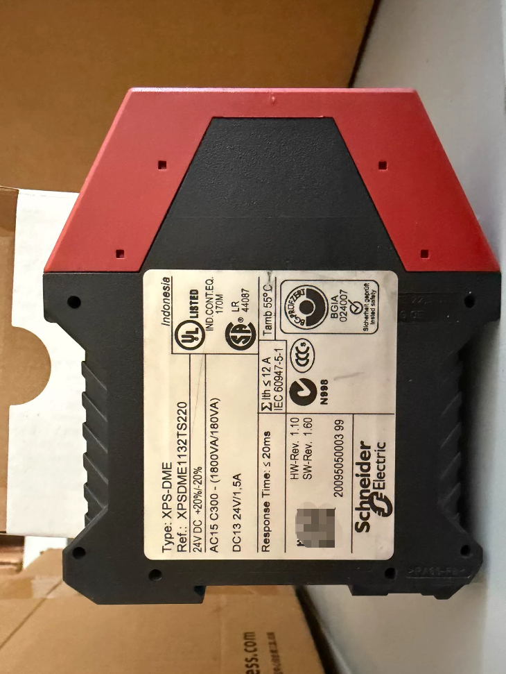

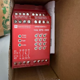
Desglose del modelo (XPS-DME-XPSDME1132TS220)
- XPS: Módulos de control de seguridad serie Preventa
- DME: Especializado en interruptores magnéticos codificados de puertas de seguridad.; soporta hasta 6 interruptores magnéticos, mientras que DMB solo admite 2 interruptores
- 1132: Especificaciones básicas
11: 24Fuente de alimentación VCC
32: 2 contactos de seguridad normalmente abiertos + 2 salidas de señal de transistores
- TS220: Terminales de reinicio manual AC220V
(El XPSDME1132 estándar solo admite reinicio de 24 V; TS220 acepta señales de reinicio AC220V)
- Aplicaciones principales
Emparejado con Schneider puertas de seguridad magnéticas sin contacto codificadas (XCS-DMC / XCS-DMP), Se utiliza para monitorear puertas protectoras en máquinas herramienta., Equipos de embalaje y líneas de producción automatizadas.:
Un solo módulo puede conectar hasta 6 interruptores magnéticos codificados en serie, logrando la más alta calificación de seguridad Cat.4 / pl y
Corta instantáneamente el circuito de seguridad al abrir la puerta., rotura de alambre, cortocircuito o falla del interruptor
Las salidas de transistor envían diagnósticos de fallas al PLC; Los LED del panel frontal indican fallas de canal
- Calificaciones de certificación de seguridad (Información clave)
| Estándar | Clasificación |
| ISO 13849-1 | Categoría 4, pl y |
| CEI 61508 / CEI 62061 | SIL 3 / SILCL3 |
| Normas de seguridad de maquinaria | EN 1088, EN 60204-1 |
| Certificaciones | CE, UL, TUV |
- Especificaciones eléctricas
4.1 Fuente de alimentación
Clasificado: 24 VCC (rango permitido: 17~30 VCC), consumo de energía ≤3.5W
4.2 Entradas de seguridad (Canales de interruptor magnético)
Corriente de entrada: 8Detección de pulso mA, protección contra cortocircuitos anti-bypass
Resistencia máxima del cable por circuito: 100Oh
Longitud máxima de cable por canal: 2000metro
Dispositivos monitoreados máximos: 6 interruptores magnéticos codificados en serie (Cat.4); más que 6 cambia la calificación de degradación a Cat.3
4.3 Contactos de salida
- Principales contactos de seguridad (2 contactos NA de guiado forzado)
Corriente térmica Ith=6A por canal, corriente combinada total ≤12A
carga de CA: 230VCA 0,75A (AC15)
carga CC: 24VCC 1,5 A (DC13, L/R=50ms)
Protección de salida: 4Un fusible gG / 6Un fusible de acción rápida
- Salidas de señal del PLC (2 transistores de estado sólido)
Carga mínima: 17V / 10mamá
La salida se abre durante fallas o apertura de puerta para diagnóstico de nivel superior
4.4 Función de reinicio (Exclusivo TS220)
Los terminales de reinicio admiten el reinicio manual activado por 24 V CC o 220 V CA.
Tiempo de respuesta: ≤20ms
4.5 Ambiental & Datos mecánicos
Temperatura de funcionamiento: -10℃ ~ +55 ℃
Temperatura de almacenamiento: -25℃~+85℃
Clase de protección: Vivienda IP40, terminales IP20
Montaje: 35carril DIN mm, dimensiones 22,5×109×117mm
Terminales: Terminales de tornillo, sección transversal del cable 0,14~2,5 mm²
- Breve definición de terminal
- Fuente de alimentación: A1(24V+) / A2(0V)
- 6 canales de entrada de interruptor magnético: Canales agrupados S11-S12 / T11-T13
- Reiniciar el circuito: Y1-Y2 (TS220 compatible con CA 220V / Pulsadores de reinicio DC24V)
- Salidas de seguridad: 13-14, 23-24 (2 contactos de seguridad normalmente abiertos)
- Salidas de transistores de diagnóstico: 31-32, 41-42 (Retroalimentación del estado del PLC)
- Solución de reemplazo obsoleta (Actualización oficial)
La serie XPS-DME ha sido descontinuada. Modelo de reemplazo directo: XPSUDN13AP
Descripción de reemplazo
- Compatibilidad funcional total: Soportes 6 interruptores magnéticos codificados, Cat.4 PL y SIL3
- reinicio universal: XPSUDN13AP acepta reinicio de 24 VCA/CC y 220 VCA, Cubriendo completamente los requisitos TS220.
- Las definiciones de terminales coinciden uno a uno; no se requiere modificación del cableado del gabinete
- Mismo ancho de carril DIN de 22,5 mm; no es necesario ajustar el espacio del gabinete
- Escenarios de aplicación típicos
- Puertas protectoras de seguridad para centros de mecanizado y máquinas de moldeo por inyección.
- Vallado de células de trabajo robóticas y puertas de acceso para líneas de producción automatizadas
- Bloqueos de puertas magnéticos sin contacto para envases de alimentos y equipos con baterías de iones de litio
- Maquinaria multipuerta (3~6 puertas de protección controladas por un relé de seguridad)
- Puntos clave para la resolución de problemas
- LED de canal rojo iluminado: Interruptor magnético correspondiente abierto, rotura de cable o cortocircuito
- No hay respuesta al botón de reinicio: Voltaje del circuito de reinicio no coincidente (verificar el suministro AC220/DC24 para TS220), soldadura por contacto
- Las salidas de seguridad no cierran: Fallo del canal de entrada, reinicio incompleto, suministro de subtensión
- No hay señal de retroalimentación al PLC: Carga de salida de estado sólido por debajo de 10 mA
Escenarios de aplicación del relé de seguridad Schneider XPSDME1132TS220
Condiciones previas para la compatibilidad del producto
Este módulo está especialmente diseñado para interruptores de puerta de seguridad magnéticos codificados Schneider. (XCS-DMC / XCS-DMP). Arriba a 6 Los interruptores magnéticos sin contacto se pueden conectar en serie., con clasificación de seguridad Cat.4 / pl y / SIL3. Admite reinicio manual de doble voltaje (CA 220 V/CC 24 V) y es ideal para maquinaria con múltiples puertas de seguridad.. Libre de desgaste por contacto mecánico, resistente al polvo y al agua para entornos operativos hostiles.
- Industria de procesamiento de máquinas herramienta
- Vertical / Centros de mecanizado horizontales, Fresadoras CNC, Tornos
Puertas protectoras delanteras y traseras de la máquina, Puertas de acceso al almacén de herramientas., Escudos de seguridad del husillo monitoreados en serie.. La energía del servo y del husillo se corta inmediatamente al abrir la puerta.. Los interruptores magnéticos sin contacto resisten la acumulación de refrigerante y virutas de metal sin los fallos de atasco que se observan en las cerraduras mecánicas de las puertas..
- Muelas, Prensas punzonadoras, Prensas plegadoras, Tijeras
Cercas de seguridad y puertas de acceso a moldes para equipos de estampado de chapa., Cumple con la norma de seguridad de maquinaria EN1088 para evitar lesiones por aplastamiento al abrir accidentalmente la puerta.. Varias puertas monitoreadas colectivamente; La apertura de cualquier puerta activa la parada de emergencia del circuito de seguridad de toda la máquina..
- electroerosión & Máquinas de corte de alambre
Puertas de protección selladas para recintos de fluidos dieléctricos. Los interruptores magnéticos eliminan la oxidación de los contactos en ambientes húmedos., Adecuado para condiciones de trabajo húmedas y corrosivas..
- Líneas de producción automatizadas & Células de trabajo robóticas
- 6-Robots de eje, Cercado robótico colaborativo
3~6 puertas de valla de seguridad segmentadas que rodean células robóticas conectadas en serie a este módulo. Los servoaccionamientos del robot se cortan instantáneamente si se abre alguna puerta. Dos salidas de diagnóstico de transistores se conectan al PLC para identificar puertas defectuosas y facilitar el mantenimiento..
- Líneas de montaje, Estaciones de carga/descarga de robots
Puertas laterales de acceso a equipos y puertas protectoras de recuperación de material para líneas de producción continua. Los interruptores magnéticos ofrecen una vida útil mucho más larga que los interruptores mecánicos de puertas de seguridad., reducir el tiempo de inactividad para reparaciones.
- Almacenamiento automatizado, Apiladores, Gabinetes AGV
Puertas de seguridad para mantenimiento de racks y protecciones de aislamiento de equipos.. Admite una longitud máxima de cable de 2000 m para cableado de larga distancia, adecuado para grandes almacenes.
- Embalaje, Impresión & Equipos de caucho/plástico
- Moldeadores por Inyección, Moldeadores por soplado, Extrusoras
Puertas de acceso al molde y protectores de seguridad de barriles para alta temperatura., ambientes aceitosos. Los interruptores magnéticos codificados evitan la manipulación de derivación y los cortocircuitos ilegales de las puertas de seguridad..
- Máquinas de envasado de alimentos, Formadores de cajas de cartón, Selladores
Líneas de producción de alimentos que requieren limpieza mediante lavado. Los interruptores magnéticos tienen una clasificación de impermeabilidad IP67 resistente al enjuague con agua.. El monitoreo centralizado de múltiples puertas de protección cumple con las normas de seguridad de maquinaria alimentaria..
- Imprentas, Laminadores, Cortadoras
Puertas protectoras que cubren conjuntos de transmisión de rodillos. Los equipos de alta velocidad exigen un corte rápido del circuito de seguridad; tiempo de respuesta del módulo ≤20ms.
- Nueva energía & Equipo de batería de litio
- Recubrimiento de iones de litio, Devanado, Llenado de electrolitos, Equipo de formación
Puertas de seguridad para cámaras de procesamiento de células selladas. Los interruptores sin contacto eliminan los riesgos de chispas eléctricas para cumplir con los requisitos a prueba de polvo y explosiones de los talleres de litio.. Puertas de varias cámaras conectadas en serie, con clasificación de seguridad PL e que cumple con los estándares de aceptación de equipos de litio.
- Corte de obleas de silicio fotovoltaico, Equipo de laminación de módulos
Los entornos de producción con mucho polvo evitan el bloqueo mecánico causado por la entrada de polvo., Garantizar un acceso de mantenimiento seguro para los operadores..
- Logística & Equipo de transporte pesado
- Líneas de clasificación automática, Gabinetes para cinta transportadora pesada
Puertas laterales de mantenimiento en máquinas clasificadoras de gran tamaño; arriba a 6 Las puertas comparten un relé de seguridad para ahorrar espacio en la instalación del gabinete.. El diseño estrecho de riel DIN de 22,5 mm se adapta a gabinetes de control densamente poblados.
- Plataformas elevadoras, Prensas hidráulicas, Máquinas de fundición a presión
Puertas protectoras de seguridad para equipos de energía hidráulica.. Los contactos de seguridad guiados forzadamente cuentan con autodetección de soldadura de contacto para eliminar modos de falla peligrosos.
- Automatización personalizada general & Equipo de prueba
- Máquinas de ensayo de materiales, Bancos de pruebas de impacto, Cámaras de prueba de alto voltaje
Puertas de seguridad para recintos de prueba sellados en alta tensión / Zonas de riesgo de impacto con protección de enclavamiento de múltiples puertas.. El restablecimiento de 220 V CA coincide con los circuitos de control de CA de planta estándar sin módulos de conversión de energía adicionales.
- Equipo de entrenamiento, Pequeños bancos de entrenamiento automatizados
Puertas de guardia de entrenamiento de estaciones múltiples. Las salidas de diagnóstico PLC duales facilitan la recopilación del estado de seguridad de nivel superior para la enseñanza de sistemas de monitoreo.
- Escenarios de aplicación inadecuados (Errores en la selección de modelos)
- Aplicaciones de puertas de protección única (Se recomienda el modelo más pequeño de la serie XPSDME01 para un mejor rendimiento de costos)
- Circuitos dedicados para botones de parada de emergencia., tapetes de seguridad o cortinas de luz (Este modelo solo admite interruptores de puerta magnéticos codificados y no puede conectar cortinas de luz directamente. / paradas de emergencia)
- Zona de alto riesgo 1 / Zona 2 atmósferas explosivas (Se requieren interruptores y cajas magnéticos a prueba de explosiones como accesorios correspondientes.)
- Más que 6 puertas de protección cableadas en serie (excesivo 6 Los interruptores reducen la clasificación de seguridad a Cat.3, incumplimiento de los estándares de aceptación de equipos de alta gama)
Resumen de las ventajas principales para las aplicaciones
- Monitorización centralizada para maquinaria multipuerta (2~6 puertas de guardia) para reducir la cantidad de relés de seguridad
- Interruptores magnéticos sin contacto compatibles con entornos hostiles que contienen aceite, polvo, limpieza de humedad y lavado
- Reinicio de 220 V CA adecuado para modernizaciones de equipos antiguos sin reemplazar los botones de reinicio de 220 V existentes
- Clasificación de seguridad Cat.4 más alta, Cumple con la aceptación de certificación TÜV/UL para equipos exportados a la UE y América del Norte.
Instalación completa estándar & Procedimientos de puesta en servicio del relé de seguridad Schneider XPSDME1132TS220
- Preparación previa a la instalación (Regla de seguridad: Todas las operaciones realizadas con energía desconectada)
1.1 Herramientas & Materiales
Phillips & destornilladores planos, multímetro, cinta aislante electrica, bridas para cables, cable de par trenzado blindado (dedicado a interruptores magnéticos)
Interruptores de puerta magnéticos codificados compatibles: XCS-DMC / XCS-DMP (No se pueden conectar cerraduras mecánicas comunes ni cortinas de luz.)
Pulsador de reinicio: Pulsador universal de reinicio automático para AC220V/DC24V (Los terminales Y1-Y2 admiten voltajes duales.)
Especificaciones de cables: Cables de control 0,5~1,5 mm²; Cables de alimentación de salida de seguridad 1,0 ~ 2,5 mm²
1.2 Ambiental & Inspección del estado de instalación
- Temperatura de funcionamiento del armario de control: -10℃ ~ +55 ℃, Mantener alejado de fuentes de interferencias electromagnéticas fuertes, como inversores y contactores.
- Ancho del módulo 22,5 mm para carril DIN estándar de 35 mm; reserve un espacio libre de ≥15 mm por encima y por debajo para la disipación de calor
- Tome medidas de protección contra el polvo., Líquido de corte y humedad dentro de los gabinetes.. La clasificación IP40 del módulo restringe el uso dentro de gabinetes únicamente; Prohibido el montaje directo en exteriores.
- Confirmar suministro de energía: Módulo A1/A2 fijo 24VDC (17~30 VCC); circuito de reinicio suministrado independientemente por AC220V o DC24V
1.3 Inspección visual previa a la instalación
Vivienda intacta, sin terminales quemados, LED indicadores funcionales
Verificar modelo: XPSDME1132TS220 (TS220 = variante de reinicio AC220V; no intercambiar con el estándar XPSDME1132)
Confirmar máximo 6 interruptores magnéticos codificados en serie; más que 6 Los dispositivos degradan la clasificación de seguridad a Cat.3
- Pasos de instalación del hardware
Paso 1: Montar el módulo en el carril DIN
- Cortar el suministro eléctrico total del gabinete; confirmar la desconexión total de la alimentación de 24 VCC y 220 VCA
- Enganche los pestillos inferiores del módulo en el riel de 35 mm, presione el módulo hacia abajo hasta que el pestillo superior se bloquee automáticamente
- Agite ligeramente hacia la izquierda y hacia la derecha para confirmar el montaje firme.. No se requieren espacios cuando se instalan varios módulos uno al lado del otro; mantener canales de disipación de calor sin obstrucciones
Paso 2. Estándares de cableado del sistema (Requisitos EMC obligatorios)
- Separación de fuertes & Circuitos de corriente débil
Ruta de los cables de señal de control de 24 V. (interruptores magnéticos, Diagnóstico del PLC) por separado de los cables de reinicio y de alimentación principal de 220 V CA en canales distintos con una separación de ≥10 cm; Prohibidos los largos recorridos paralelos dentro del mismo conducto.
Utilice cable blindado trenzado para interruptores magnéticos.; Conexión a tierra de un solo extremo de la capa protectora dentro del gabinete de control.
- Manejo de canales no utilizados (Crítico)
Este módulo contiene 3 grupos de entradas de doble canal S1, T2, T3, cada uno con terminales Sx1-Sx2, Sx1-Sx3:
Canales de alambre correspondientes a puertas instaladas.; cortocircuito Sx1 y Sx3 para todos los canales no utilizados. De lo contrario, las fallas de canal se activarán al encender y el reinicio se desactivará.
Ejemplo: Solo 2 puertas utilizadas: S31-S33 corto con cable de puente; todo 3 grupos de canales cableados para 6 puertas
- Par de apriete de terminales 0,6~0,8N·m; sin hilos de cobre sueltos ni cortocircuitos entre terminales en los conductores
Paso 3. Definición completa del cableado de terminales
- Circuito de alimentación principal (Fijo 24 VCC)
A1: 24VCC Positivo; A2: 0VCC Negativo
- Canales de entrada de interruptor magnético (Redundancia de doble canal, núcleo para Cat.4)
T11/T12/T13: 1interruptores magnéticos del primer grupo; S21/S22/S23: 2segundo grupo; S31/S32/S33: 3tercer grupo
Dos contactos de cada interruptor magnético codificado están conectados en serie a los correspondientes Sx2 y Sx3.; todos los terminales comunes Sx1 conectados en paralelo
- Restablecer el circuito Y1-Y2 (TS220 Exclusive Dual-Voltage)
AC220V reset: Y1 connected to Live L, Y2 connected to Neutral N, in series with self-reset pushbutton
DC24V reset: Y1 connected to 24V+, Y2 connected to 0V, in series with self-reset pushbutton
Select only one voltage type; simultaneous connection of 220V and 24V prohibited
- Forced-Guided Safety Outputs (Cut off servo / main contactor circuits, wired in series)
13-14, 23-24: 2 SIN contactos de seguridad, max load 6A per channel, AC230V 0.75A (AC15)
The two contacts must be wired in series for safety circuit to satisfy Cat.4 redundant safety requirements
- PLC Solid-State Diagnostic Outputs (Passive transistor feedback)
31-32, 41-42: Open-circuited during door faults / door opening; conductive after all doors closed and reset executed, connected to PLC digital inputs
Paso 4. Power-Down Post-Wiring Inspection (Mandatory Before Power-Up)
- Multimeter continuity test: All closed magnetic switch channels Sx2-Sx3 conductive; canales no utilizados en cortocircuito Sx1-Sx3 conductivos
- Pulsador de reset normalmente abierto, cerrado cuando se presiona; No hay cortocircuitos en el cable a tierra.
- Sin cortocircuitos a tierra o fuente de alimentación en los terminales de salida de seguridad 13/14, 23/24
- No hay polaridad inversa ni cortocircuito en el suministro de 24 V A1/A2
- Proceso de puesta en marcha paso a paso
Fase 1: Autoprueba de encendido (Prueba de módulo desnudo sin carga)
- Energice primero el suministro de 24 VCC del módulo, luego aplique energía AC220V para restablecer el circuito
- 2-Autotest del segundo módulo: Todos los LED se iluminan simultáneamente; Los circuitos internos detectan automáticamente los cortocircuitos., Roturas de cables y anomalías del canal.
- Diferenciación de estado después de completar la autoprueba:
LED de funcionamiento verde fijo: Fuente de alimentación normal; todos los LED de canal rojos apagados: Todas las puertas cerradas, sin fallas de cableado
LED rojo parpadeante en cualquier canal: Rotura del hilo del canal correspondiente, cortocircuito, interruptor magnético no accionado o canal no utilizado en cortocircuito
Fase 2: Puesta en marcha de la función de reinicio básica
- Cierre completamente todas las puertas de protección y confirme que todos los LED de los canales rojos se apaguen.
- Presione el botón de reinicio durante ≥0,5 segundos y luego suéltelo.
- Rendimiento normal: El LED verde de salida OUT se ilumina, terminales 13-14/23-24 conducta, salidas de transistores 31-32/41-42 encender, El PLC recibe la señal listo
- Anomalía: No hay respuesta cuando se presiona el botón de reinicio
Solución de problemas 1: Una puerta no completamente cerrada / interruptor magnético desalineado
Solución de problemas 2: Canal de entrada no utilizado y sin cortocircuito
Solución de problemas 3: Voltaje del circuito de reinicio no coincidente, contacto del pulsador normalmente abierto dañado
Solución de problemas 4: Cableado invertido o roto en terminales Y1/Y2
Fase 3: Prueba de simulación de función de seguridad (Elemento Obligatorio para la Aceptación de Equipos)
Prueba 1: Parada de la máquina activada por la apertura de una sola puerta
- Salidas del módulo cerradas normalmente, equipo listo para operar
- Abre cualquier puerta de seguridad.
Respuesta estándar: El LED verde de salida se apaga en ≤20 ms, ambos contactos de seguridad se abren simultáneamente, Las salidas de diagnóstico del PLC se desenergizan
Después de volver a cerrar la puerta, reset button must be pressed again to restore outputs (manual reset mode; no automatic reset for this model)
Prueba 2: Wire Break Fault Simulation (Cat.4 Self-Diagnosis)
- Desconecte la fuente de alimentación, remove wire from any Sx2 terminal to simulate wire breakage
- Re-energize power; corresponding red fault LED stays solidly illuminated
- Reset operation ineffective even with all doors closed; module latches fault state and cuts safety outputs
- After restoring wiring, power cycle module then close all doors and reset to clear fault
Prueba 3: Multi-Door Interlock Test (2~6 Doors)
- Partial door closure with one door open: Reset disabled, fault LED alarm triggered
- Reset after all doors fully closed to energize outputs; immediate machine stop upon opening any single door
- Verify dual PLC diagnostic outputs distinguish global fault signals
Prueba 4: Reset Voltage Compatibility Test (TS220 Feature)
For AC220V reset: Desconecte el suministro de reinicio de 24 V, solo energice 220VAC; La función de reinicio funciona normalmente.
Para reinicio de actualización DC24V: Desconecte el suministro de 220 VCA, solo energice 24VDC; La función de reinicio funciona normalmente.
Prohibido el suministro simultáneo de 220 V CA y 24 V CC a Y1-Y2, quemará el circuito de reinicio
Fase 4: Puesta en marcha de coordinación de carga completa de la máquina
- Contactos de seguridad de alambre 13-14 y 23-24 en serie con el contactor principal / circuito de habilitación de servo
- Se permite la puesta en marcha del equipo después de un reinicio exitoso
- Apertura de puerta durante el estado de funcionamiento: El contactor principal se abre instantáneamente, corte de energía sin movimiento peligroso
- Verificación de carga de fallas: El PLC recopila señales de 31-32/41-42; La pantalla táctil muestra alarmas de falla de la puerta de guardia.
- Criterios de aceptación al finalizar la puesta en servicio
- No se detectaron fallas durante la autoprueba de encendido; Las salidas se activan normalmente después del cierre y reinicio de la puerta.
- El circuito de seguridad se corta instantáneamente dentro <20ms al abrir cualquier puerta
- Bloqueo de fallos fiable provocado por roturas de cables o cortocircuitos; El equipo no se puede iniciar ilegalmente.
- Prueba de conmutación normal de circuitos de reinicio AC220V/DC24V
- Conexión/desconexión sincrónica de contactos de seguridad duales, eliminando el riesgo de falla de un solo punto (Cat.4/PL e)
- Retroalimentación precisa de la señal de diagnóstico del PLC para la identificación remota de fallas
- Instalación & Prohibiciones de puesta en servicio + Búsqueda rápida de fallos
Operaciones estrictamente prohibidas (Reglas de seguridad estrictas)
- No conecte puertas de seguridad mecánicas estándar., cortinas de luz o paradas de emergencia a canales de entrada Sx (Sólo son compatibles los interruptores magnéticos codificados XCS-DMC/DMP.)
- No encienda el módulo si los canales no utilizados no están en cortocircuito: el módulo bloquea la falla permanentemente
- No cablear sólo uno de los dos contactos de seguridad.; calificación de seguridad invalidada, la aceptación del equipo falló
- No suministre AC220V y DC24V a los terminales Y1-Y2 simultáneamente
- No coloque cables de alimentación y cables de señal en largos tramos paralelos dentro del mismo canal.; La interferencia electromagnética provoca paradas involuntarias de la máquina.
Resolución rápida para fallas comunes de puesta en servicio
- LED de canal rojo fijo iluminado
Puerta no completamente cerrada, espacio de montaje excesivo en el interruptor magnético; rotura de cable/cortocircuito; canal no utilizado no en cortocircuito
- No hay respuesta al botón de reinicio
No hay energía para restablecer el circuito, pulsador dañado; fallo de canal no borrado; cierre incompleto de todas las puertas
- LED de salida parpadeante, tropezones frecuentes
Resistencia excesiva del cable debido a un cableado demasiado largo (>100Ω a través del circuito); Mala conexión a tierra del blindaje que causa EMI; emparejamiento de codificación fallido del interruptor magnético
- No se envía ninguna señal de diagnóstico al PLC
Corriente de carga de salida del transistor inferior a 10 mA; coincide con la clasificación de corriente de entrada del PLC
- Mantenimiento de rutina & Puntos clave de puesta en servicio
- Inspección diaria: Estado de ejecución, LED de salida y fallo
- Nueva prueba trimestral de las funciones de seguridad de rotura de cable y tope de puerta
- Es obligatoria la repetición completa de las pruebas de simulación de fallas después de reemplazar cualquier interruptor magnético.
- Para modernizaciones de equipos heredados, priorice el modelo de reemplazo XPSUDN13AP para nuevos proyectos con lógica de instalación y puesta en servicio idéntica





NH42-63-318x560.png "Interruptores de transferencia automática tipo PC CHINT (ATS)NH42-63/4SZ")



