 contactor,cortacircuitos,sensor,Codificador,SOCIEDAD ANÓNIMA,Convertidor

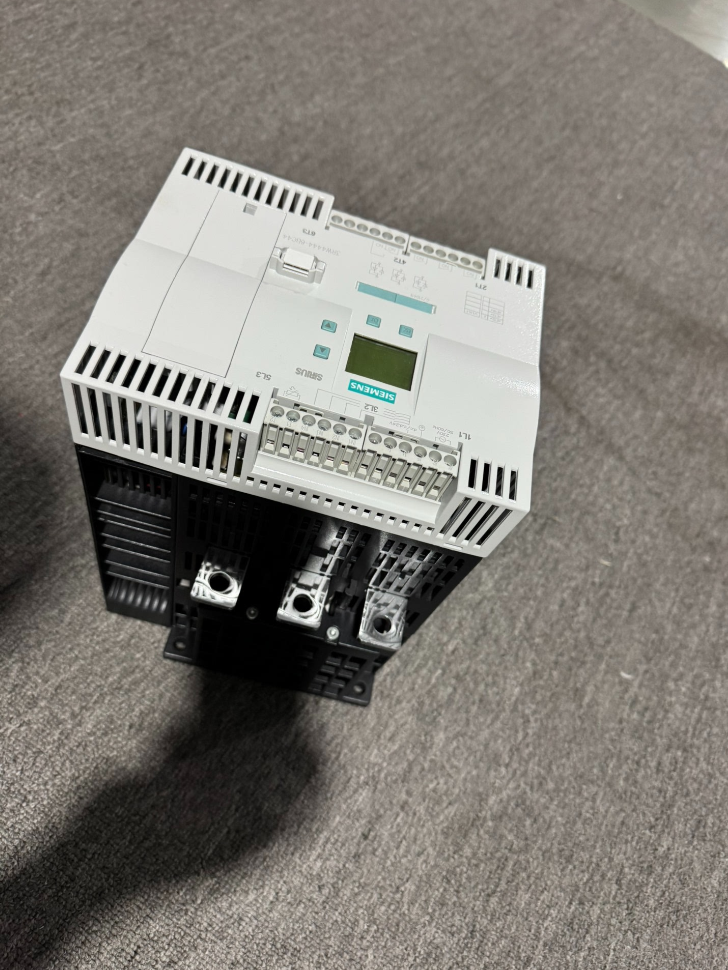

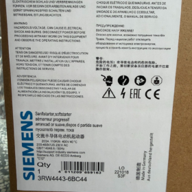
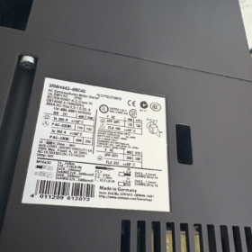
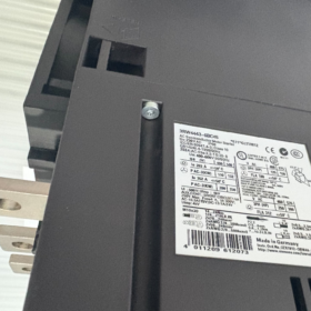
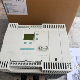
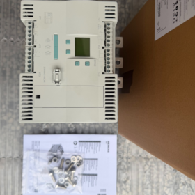
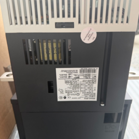
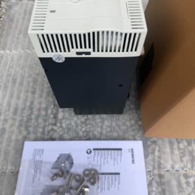
Desglose del código de pedido MLFB
3RW 44 43 6 antes de Cristo 4 4
- 3RW: Serie de productos de arrancadores suaves SIRIUS
- 44: Bypass integrado de alto rendimiento trifásico totalmente controlado arrancador suave (Regulación independiente por tiristores por fase., contactor de derivación integrado de serie)
- 43: Código de talla, corriente nominal 203 un en 40 °C para cargas estándar
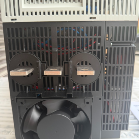
- 6: Tipo de terminal del circuito de control = terminales de tornillo; Circuito principal conectado mediante barras colectoras de cobre.
- B: Contactor de derivación integrado (2/3-derivación de fase para pérdida cero durante el funcionamiento en estado estable)
- do: Control independiente de tiristores trifásicos (Control trifásico completo para equilibrar las corrientes trifásicas.)
- 4: Tensión de alimentación de control Us = CA 230 V
- 4: Tensión de funcionamiento del circuito principal Ue = CA 200~460 V
- Parámetros eléctricos básicos (40 °C, Clase 10 Carga estándar)
| Artículo | Valor del parámetro |
| Corriente nominal para cableado estándar (Motor conectado directamente al arrancador suave.) | 203 A |
| Potencia del motor adaptada a 400 V | 110 kilovatios |
| Corriente nominal para conexión dentro del triángulo (Los devanados del motor se dividen en dos ramas.) | 352 A |
| Potencia del motor adaptada a 400 V para cableado interior en triángulo | 200 kilovatios |
| Rango de voltaje del circuito principal | CA 200~460 V (50/60 Hz) |
| Controlar el suministro | C.A. 230 ±10% |
| Modo de control de fase | Tiristores antiparalelos por fase con regulación independiente |
| Funciones estándar | Contactor de derivación integrado para evitar los tiristores durante el funcionamiento |
| Clase de viaje por sobrecarga estándar | Clase 10; Clase 10/20/30 configurable manualmente |
| Funciones de protección | Pérdida de fase, desequilibrio de fase, sobrecarga del motor, calentamiento excesivo, cortocircuito del tiristor, tiempo de espera de inicio, detección de falla a tierra |
| Expansión de la comunicación | Compatible con Profibus DP (requiere módulo de comunicación 3RW4900-0KC00) |
| Peso | Aprox.. 11.2 kilos |
| País natal | Alemania |
III. Coincidencia de carga & Límites de selección
- Cargas aplicables
bombas de agua, fans, cintas transportadoras, compresores de aire, enfriadores, equipo centrífugo (velocidad fija, sólo se requiere un arranque/parada suave)
- Referencia de reducción de potencia para operación de servicio pesado (40 °C)
Clase 20 trabajo pesado (inicios frecuentes, alto par de arranque): corriente permitida 170 A, motor combinado 90 kilovatios
Clase 30 trabajo extra pesado (molinos de bolas, trituradoras): corriente permitida 145 A, motor combinado 75 kilovatios
- Condiciones de funcionamiento prohibidas
Regulación de velocidad continua, conmutación frecuente hacia adelante/hacia atrás, jogging de alta frecuencia (≥30 veces por hora)
- Estructura de hardware & Descripción del cableado
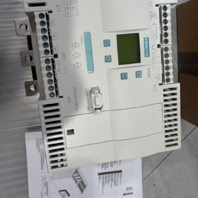
- Circuito principal: Terminales de barras de cobre; Entrada lateral de línea L1/L2/L3, Salida del lado del motor T1/T2/T3; Admite cableado estándar y cableado interior en triángulo.
- Circuito de control: Terminales de tornillo para señales de arranque/parada., salidas de fallo, reiniciar, entrada de termistor externo
- Panel del operador: Pantalla LCD incorporada para configurar la rampa de inicio, voltaje inicial, parada suave, límite actual y umbrales de protección
- Instalación: Montaje en pared vertical; mínimo 150 mm de espacio libre superior/inferior para disipación de calor; temperatura ambiente 0~40 °C (reducción de potencia para temperaturas superiores 40 °C)
- Ciclo de vida del producto & Modelos de reemplazo
- Estado: 3Serie RW44 descatalogada (PLM: PM490 fase de fin de soporte); El fabricante original detiene la producción en masa., solo repuestos en stock disponibles
- Modelo de reemplazo directo OEM (Recomendado para nuevos proyectos)
3RW5543-6HA14 (Serie 3RW55 de nueva generación, mismo 203 Una corriente nominal, 230 Alimentación de control V, 200-460 voltaje principal, terminales de tornillo, bypass integrado)
- Diferencias entre lo viejo & Nuevos modelos
Huella más pequeña, menor consumo de energía, Modbus RTU nativo y lógica de protección optimizada para 3RW55
Diferentes dimensiones de recorte de montaje; Las barras colectoras de cobre y los soportes de montaje necesitan modificaciones durante la modernización del gabinete.
- Dispositivos de protección compatibles recomendados
- Protección contra cortocircuitos del circuito principal: Disyuntor de caja moldeada adaptado a 110 circuito del motor kW
- Protección especializada de tiristores: Fusible ultrarrápido aM/gR 500 V 315 A (obligatorio aguas arriba del arrancador suave, sin protección contra cortocircuitos de tiristores sin él)
- Protección adicional del motor: Termistor PTC externo conectable a terminales de control para protección de sobredisparo del devanado
VII. Matriz típica de solución de problemas
| Síntoma de falla | Causa principal | Solución |
| Alarma de sobrecalentamiento durante el arranque | Conducto de aire de refrigeración bloqueado / temperatura ambiente superior 40 °C / arranque de carga pesada de larga duración | Limpiar el polvo, mejorar la ventilación del gabinete, actualizar a un arrancador suave de mayor calificación |
| Alarma de pérdida de fase | Pérdida de energía monofásica, conexión de barra suelta, bobinado del motor roto | Apretar el cableado, medir el voltaje de entrada trifásico y la resistencia del devanado del motor |
| Corriente de arranque ilimitada, salida directa de voltaje completo | Tiristores averiados, contactos de contactor de derivación soldados | Desconecte la fuente de alimentación para probar los tiristores.; reemplazar el módulo de contacto de derivación |
| Viaje de tiempo de espera de inicio | Tensión inicial demasiado baja, carga mecánica agarrotada, tiempo de rampa insuficiente | Aumentar el voltaje inicial, inspeccionar la carga mecánica, ampliar el tiempo de rampa de inicio |
VIII. Ventajas clave
- Regulación de voltaje trifásico independiente; Elimina el desequilibrio de corriente trifásico común en arrancadores suaves bifásicos., Ampliación de la vida útil de los rodamientos del motor.
- El bypass integrado elimina la pérdida de energía del tiristor durante el funcionamiento constante, entregando 98% modelos de ahorro de energía versus modelos sin bypass
- Admite la supresión del golpe de ariete con parada suave y parada de la bomba, ideal para suministro de agua, sistemas de drenaje y climatización
- Protección integral del motor integrada, eliminando la necesidad de relés de sobrecarga térmica separados
Especificaciones de dimensiones completas de siemens 3RW4443-6BC44
- Dimensiones generales del equipo (Ancho × Alto × Fondo, Unidad: milímetros)
210 (Ancho) × 230 (Altura) × 298 (Profundidad)
- Recorte de montaje & Dimensiones de fijación
- Distancia central horizontal entre orificios de montaje: 167 milímetros
- Distancia central vertical entre orificios de montaje: 190 milímetros
- Especificación del sujetador: perno m8, par de apriete 15 Nuevo Méjico
- Ancho mínimo reservado del recorte del panel del gabinete ≥210 mm, altura ≥230 mm
III. Espacio libre mínimo obligatorio en el gabinete para la disipación de calor (Montaje en pared vertical)
Liquidación superior: ≥100 milímetros
Espacio libre inferior: ≥75 milímetros
Espacio libre lateral (varias unidades una al lado de la otra): ≥5 milímetros
Superficie trasera del equipo a placa posterior del gabinete: contacto directo permitido
- Dimensiones exteriores de la caja (almacenamiento & Referencia Logística)
348 × 433 × 394 milímetros, peso neto 11.22 kilos
- Notas complementarias
- Clase de protección: IP00; solo para instalación en gabinete
- Todas las variantes del 3RW4443 (-6BC34/-6BC44/-2BC45) comparten dimensiones generales idénticas; diferencias solo en los terminales de control y voltaje de suministro
- El modelo de repuesto 3RW5543-6HA14 ocupa menos espacio; recalcular el tamaño del recorte del gabinete para modificaciones
Lista completa & Definición de funciones de terminales de control – Siemens 3RW4443-6BC44
Este modelo está equipado con terminales de control tipo tornillo., categorizado en cinco grupos: controlar la fuente de alimentación, entradas digitales, detección de temperatura PTC del motor, salidas de relé programables, relé de falla general.
- Terminales de fuente de alimentación de control (Suministro principal de la unidad)
- A1, A2
Función: Fuente de alimentación de control principal para arrancador suave
Calificación del modelo: C.A. 230 ±10%, 50/60 Hz
regla de cableado: A1 línea viva L, A2 línea neutra N
- educación física
Terminal de tierra protectora del circuito de control; conectar a la barra colectora de tierra del gabinete
- L+, l-
Alimentación auxiliar interna integrada de 24 V CC para interruptores de entrada digitales pasivos; externo 24 No se requiere fuente de alimentación V
L+ = polo positivo DC24 V; L= polo negativo DC24 V (terreno común)
- 4 Terminales de entrada digitales programables IN1 / IN2 / IN3 / IN4
Lógica: Conecte un extremo del interruptor a L+, el otro extremo al INx correspondiente para activar la función asignada; todas las funciones configurables a través de los parámetros del panel
Asignación predeterminada de fábrica
EN1: Arranque del motor (Grupo de parámetros 1 rotación hacia adelante)
IN2: No asignado
IN3: No asignado
IN4: Restablecimiento de disparo por falla
Todas las funciones personalizables
Modo manual local, arranque de emergencia, fluencia a baja velocidad, parada de emergencia rápida, reinicio de falla, 3 Grupos de conmutación de parámetros de motor de avance/retroceso.
III. Terminales de detección de temperatura del devanado del motor T1, T2
Para conexión de termistor PTC de motor externo (protección contra sobrecalentamiento del motor)
El arrancador suave se dispara automáticamente cuando la temperatura del devanado excede el umbral
Cortocircuito T1 y T2 si no hay PTC instalado para desactivar la protección térmica
- 3 Salidas de relé programables independientes (Contactos secos pasivos, CA 250 V. / 5 A)
Cada par consta de contactos normalmente abiertos con funciones totalmente asignables a través del menú de parámetros.
- 13, 14 Producción 1
Por defecto: Señal de funcionamiento del motor (se cierra después de completar el arranque y activar el contactor de derivación)
- 23, 24 Producción 2
Por defecto: No asignado; configurable para estado de bypass, inicio en progreso, prealarma, Frenado CC, etc..
- 33, 34 Producción 3
Por defecto: No asignado; personalizable para todo tipo de señales de estado de equipos
- Terminales de relé de falla general 95, 96, 98 (Alarma de falla global)
3-pole changeover contact for unified fault signaling, widely used in safety circuits
95: Common terminal COM
95-96: Normalmente cerrado (CAROLINA DEL NORTE): conductive when unit healthy; opens upon fault trip
95-98: Normalmente abierto (NO): closes when fault occurs, for fault indicator light / alarm horn wiring
Terminal Summary Table
| Grupo de terminales | Terminal Number | Core Purpose |
| Controlar la fuente de alimentación | A1, A2 | AC230 V control voltage input |
| Tierra protectora | educación física | Control circuit grounding |
| Incorporado 24 V Supply | L+, l- | DC24 V power for digital inputs (positivo / suelo) |
| Entradas digitales | EN1, IN2, IN3, IN4 | Start/stop, reiniciar, parameter switchover, manual mode etc. |
| PTC Temperature Sensing | T1, T2 | Motor winding overheat thermistor interface |
| Salida de relé 1 | 13, 14 | Motor running status (normalmente abierto) |
| Salida de relé 2 | 23, 24 | Customizable equipment status (normalmente abierto) |
| Salida de relé 3 | 33, 34 | Customizable equipment status (normalmente abierto) |
| Fault Changeover Contact | 95, 96, 98 | Global fault alarm (COM + CAROLINA DEL NORTE + NO) |
Supplementary Wiring Guidelines
- Tightening torque for control wires: 1.2~1.5 N·m; wire cross-section 0.75~1.5 mm² copper conductors
- Digital inputs are passive contact type; power solely from internal L+/Lwithout external PLC 24 suministro V
- Series the normally closed 95/96 contactos en el circuito de seguridad para cortar la alimentación del contactor aguas arriba en caso de falla
- La comunicación Profibus requiere un módulo 3RW4900-0KC00 independiente con puerto dedicado (No forma parte de los terminales de control delanteros.)





NH42-63-318x560.png "Interruptores de transferencia automática tipo PC CHINT (ATS)NH42-63/4SZ")



