 contactor,cortacircuitos,sensor,Codificador,SOCIEDAD ANÓNIMA,Convertidor

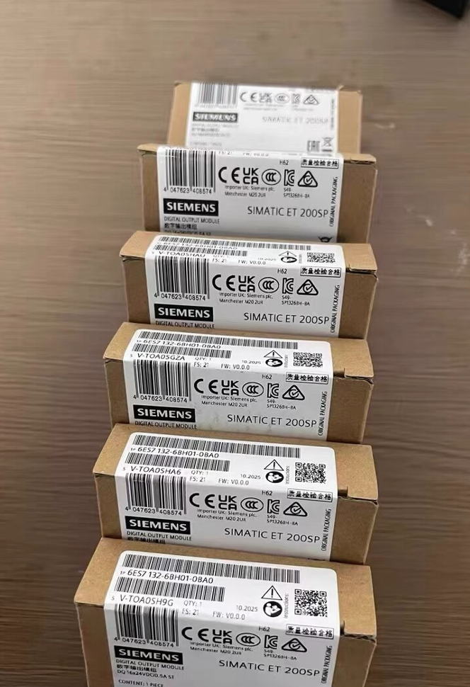

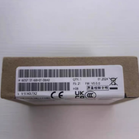
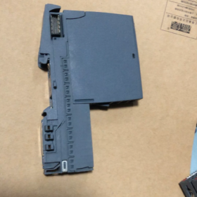
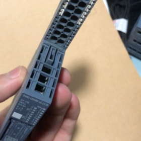
- Designación completa del modelo & Posicionamiento
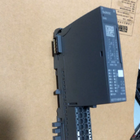
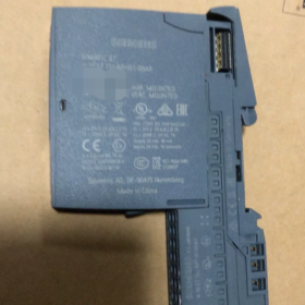
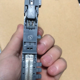
SIMATIC ET200SP DI 16×24VDC ST Módulo de entradas digitales estándar de Siemens
Serie: E/S distribuidas ET200SP (Estación remota PROFINET/PROFIBUS)
Función: 16-canal 24 Entrada digital V CC para recopilar señales de sensores PNP, como interruptores, interruptores de proximidad, sensores fotoeléctricos y finales de carrera
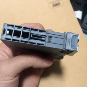
Tipo de codificación: Codificación mecánica tipo A, sólo compatible con BaseUnit tipo A0
Desglose del código del modelo
| Segmento de código | Definición |
| 6ES7131 | Entrada digital ET200SP (DE) Serie de módulos |
| 6BH01 | 16-canal 24 VCC Estándar DI, Versión de hardware V1 |
| 0BA0 | Versión industrial estándar, sin recubrimiento anticorrosión y sin mejora de supresión de sobretensiones |
- Especificaciones eléctricas básicas
2.1 Fuente de alimentación & Características de entrada
Suministro clasificado: 24 En DC, rango permitido 19.2 ~ 28.8 V, con protección contra inversión de polaridad
Tipo de entrada: P-lectura (Entrada PNP de hundimiento, CEI 61131 Tipo 3)
Lógica 0: -30 V~ +5 V
Lógica 1: +11 V~ +30 V
Corriente típica en estado activado por canal: 2.5 mamá; Corriente total máxima del módulo: 90 mamá
Consumo de energía típico: 1.7 W.
Agrupación de canales: dos grupos (Canales 0~7 / 8~15). Todos los sensores dentro de un grupo deben ser uniformemente PNP o NPN; Está prohibido el cableado mixto..
2.2 Retraso del filtro (8 niveles configurables en TIA Portal)
0.05 / 0.1 / 0.4 / 0.8 / 1.6 / 3.2 / 12.8 / 20 EM
Retardo de cable adicional de 30 ~ 500 μs. Se recomienda una configuración de filtro ≥3,2 ms para entornos con fuertes interferencias de inversores..
2.3 Longitud máxima del cable
Cable blindado: 1000 m máximo
Cable sin blindaje: 600 m máximo
- Estructura mecánica & Instalación
- Dimensiones: 15 milímetros (W.) × 73 milímetros (h) × 58 milímetros (D), diseño compacto ultra estrecho
- Clase de protección: IP20, Montaje en carril DIN únicamente dentro del armario de control
- Temperatura ambiente
Montaje Horizontal: 0 ~ +60 °C
Montaje vertical: 0 ~ +40 °C
Almacenamiento & Transporte: -25 ~ +70 °C
- Indicadores: LED verde independiente para cada canal (ENCENDIDO = Lógica 1, APAGADO = Lógica 0); no hay LED de error de hardware dedicado
- Dirección de ocupación: Consume 2 bytes de entrada más un adicional 2 bytes para información de diagnóstico de QI. interrupción de proceso, El modo isócrono y las funciones de contador no son compatibles..
- Diagramas de cableado (Unidad base tipo A0 Obligatorio)
4.1 2-contactos pasivos de alambre (Interruptores de límite, Pulsadores)
Conecte directamente a la BaseUnit A0: un terminal de contacto se conecta a DIx, el otro a m (24 V negativo). Para detección de rotura de cables, conectar un 25 ~ 45 resistencia kΩ en paralelo con el contacto.
4.2 3-Sensores PNP de alambre (Fotoeléctrico común / Interruptores de proximidad)
Se requiere terminal de distribución potencial:
Cable marrón del sensor: L+ 24 V
Cable azul del sensor: Tierra común M
Cable negro del sensor (Señal): Conectar al canal DI del módulo
> Los sensores NPN no deben conectarse directamente a este módulo; lógica 1 las señales no se pueden detectar.
4.3 2-sensores de proximidad inductivos de alambre
Corriente máxima de circuito cerrado limitada a 1.5 mamá. Los cables largos pueden generar falsas alarmas de rotura de cable.
- Funciones de diagnóstico & Limitaciones funcionales
- Admite diagnóstico de rotura de cables (Se requiere resistencia de detección en paralelo); diagnóstico de cortocircuito no disponible
- Sin protección contra sobrecorriente a nivel de canal; Los cortocircuitos del sensor no activarán alarmas de falla de canal individual.
- Sin salida de alimentación del codificador ni auxiliar 24 Alimentación VCC
- me apoya&M0 ~ yo&Información del dispositivo M3; hardware reconocido automáticamente por TIA Portal
- Compatibilidad de comunicación: CPU S7-1200/1500, CPU ET200SP, PROFINET IO, PROFIBUS-DP
- Comparación de derivados de la misma serie
| Número de modelo | Diferencias | Aplicaciones típicas |
| 6ES7131-6BH01-0BA0 | DI básico estándar sin revestimiento anticorrosión | Talleres generales, Equipo estándar bajo temperatura normal. |
| 6AG1131-6BH01-7BA0 | Revestimiento anticorrosión SIPLUS, rango de operación -40 ~ +70 °C | Plantas químicas, puertos, ambientes corrosivos de alta humedad |
| 6ES7131-6BH01-0CA0 | Supresión de sobretensiones incorporada | Cables de campo de larga distancia, áreas propensas a rayos |
| 6ES7131-6BH00-0BA0 | Modelo antiguo obsoleto, Totalmente compatible con hardware | Reemplazo de piezas de repuesto para equipos antiguos |
- Escenarios de aplicación típicos
- Líneas de montaje automotrices: Recopilación de señales para confirmación de la posición del dispositivo., Puertas de seguridad y pulsadores de estaciones de trabajo.
- Embalaje & Equipos de Logística: Conteo fotoeléctrico, interruptores de detección de atascos, clasificar señales de activación
- Sistemas de tratamiento de agua: Interruptores de nivel de flotador, interruptores de límite de válvula, señales de retroalimentación de funcionamiento de la bomba
- Automatización de máquinas herramienta: Interruptores de límite de viaje, detección de herramientas, contactos del circuito de seguridad
- Selección de modelo & Precauciones de operación
- Sólo se permiten BaseUnit del tipo A0; El tipo B0/C0 y otras unidades base codificadas son incompatibles. El módulo cuenta con un bloqueo de codificación tipo A integrado para evitar una inserción incorrecta..
- Todos los sensores dentro de cada grupo de 8 canales deben compartir la misma polaridad.; Los dispositivos PNP y NPN no se pueden mezclar en un grupo.
- Los cables tendidos cerca de inversores y servoaccionamientos deben estar blindados para eliminar activaciones falsas..
- Aumente el retardo del filtro de entrada para cables largos para suprimir la interferencia electromagnética.
- Sin certificación de seguridad SIL. Este módulo no se puede utilizar de forma independiente para circuitos de seguridad.; Se requieren relés de seguridad o módulos de E/S de seguridad..
- Opciones de reemplazo alternativas
- Reemplazo directo equivalente: 6AG1131-6BH01-7BA0 (versión anticorrosión para amplia temperatura)
- Actualización de mayor densidad: 6ES7131-6BF01-0BA0 (8-módulo DI aislado de canal)
- Reemplazo de aplicaciones de seguridad: 6ES7131-6FD01-0BB1 (DI de seguridad, SIL 2 obediente)
Principio de funcionamiento completo de agrupación de canales para 6ES7131-6BH01-0BA0
- Definición del grupo de hardware (Fijado 8 Canales por grupo, 2 Grupos Totales)
El 16 Los canales de entrada están físicamente divididos en dos dominios de potencial de referencia independientes con circuitos de hardware internos completamente separados.:
- Grupo 1: Canales DI.0 ~DI.7 (Primero 8 agujas)
- Grupo 2: Canales DI.8 ~ DI.15 (Último 8 agujas)
Lógica subyacente central: Referencia común independiente M por grupo
El módulo asigna internamente una tierra de referencia M independiente a cada grupo., sin conexión eléctrica entre los dos grupos.
Todos los canales dentro de un grupo comparten el mismo potencial del grupo M. Todo 8 Los canales de un solo grupo deben utilizar una polaridad de sensor idéntica. (todo PNP o todo NPN); Los dos grupos pueden adoptar diferentes polaridades..
- Operación de circuitos de grupos de canales.
2.1 Modo estándar (Valor predeterminado de fábrica: PNP / Lectura P hundida)
Estructura del circuito interno para cada grupo.:
Cada canal DIx se eleva internamente hasta 24 En DC
Condición de conducción de la señal.: DIx conectado a 0 V (METRO) → Circuito cerrado, El PLC detecta la lógica 1
Compatible con sensores PNP de 3 hilos y contactos pasivos de 2 hilos (pulsadores / interruptores de límite)
Reglas de cableado:
Los terminales negativos de todos los sensores del grupo se conectan uniformemente al terminal del grupo M
Los sensores PNP y NPN no pueden coexistir en un grupo; de lo contrario, los canales parciales permanecen permanentemente Lógica 0 o lógica 1.
2.2 Cableado de sensores NPN a un solo grupo (Salida de fuente)
Salida de sensores NPN de bajo nivel 0 Señales V que no se pueden reconocer por defecto. Modifique la conexión M común del grupo a 24 VL+:
DIx recibe alto nivel 24 Señal V del sensor NPN para cerrar el circuito.
Sólo es necesario ajustar el potencial común del grupo objetivo.; el otro grupo no se ve afectado.
2.3 Características clave de aislamiento de la separación de grupos
No hay conexión eléctrica entre los dos grupos.. Está totalmente permitido conectarse al Grupo. 1 m a 0 V y grupo 2 m a 24 VL+.
Los cortocircuitos o fallas a tierra en un grupo no interferirán con la adquisición de señales en el otro grupo..
Los sensores en cables largos o bucles de suministro de energía separados se pueden conectar a tierra en grupos separados para reducir la interferencia del bucle de tierra..
- Asignación entre direcciones de E/S y grupos de canales (Área de memoria del PLC)
El 16 los canales ocupan 2 bytes de entrada, estrictamente asignado por grupo en correspondencia uno a uno:
Grupo 1 (DE.0~DI.7): ``IBx'' (1st byte, bit0 ~ bit7)
Grupo 2 (TU.8 ~ TU.15): `IBx+1` (2segundo byte, bit0 ~ bit7)
Ejemplo: Dirección inicial del módulo IB100
DI0~DI7 = I100.0 ~ I100.7
DI8~DI15 = I101.0 ~ I101.7
Los datos del estado de diagnóstico de QI se cargan en dos segmentos correspondientes a cada grupo.
- Disposición de terminales de los grupos de canales correspondientes de la BaseUnit tipo A0
Lógica de disposición de terminales de la BaseUnit A0 coincidente:
- Terminales 1~8: DE.0~DI.7 (Grupo 1) + Grupo 1 M común
- Terminales 9~16: TU.8 ~ TU.15 (Grupo 2) + Grupo 2 M común
La unidad base está equipada con dos terminales M independientes físicamente separados para conectar diferentes potenciales a cada grupo..
- Tres escenarios prácticos típicos de cableado para agrupaciones
Guión 1: Todo el cableado PNP (Más común)
Grupo 1 M y grupo 2 M en corto juntos a 0 V (24 V negativo)
Sensores PNP uniformes de 3 cables e interruptores pasivos para ambos grupos sin conflicto
Guión 2: Un grupo PNP, NPN de un grupo (Permitido)
Grupo 1 (DI0~7) M conectado a 0 V → Cableado con fotoeléctrico PNP / sensores de proximidad
Grupo 2 (DI8~15) M conectado a 24 V L+ → Cableado con sensores NPN
Esta configuración es válida. Los potenciales de grupo independientes no interfieren entre sí., y todas las señales se reconocen normalmente.
Guión 3: PNP mixto & NPN dentro de un grupo (Estrictamente prohibido)
Ejemplo: DI0~4 cableado a sensores PNP, DI5~7 cableado a sensores NPN
El grupo solo tiene un potencial M compartido., creando conflictos de circuitos con los siguientes fenómenos:
Canales parciales permanentemente sin señal (lógica constante 0)
Activación falsa aleatoria y parpadeo de señal
Los casos graves provocan una sobrecarga del circuito de entrada y daños permanentes en el canal del módulo.
- Funciones de diagnóstico basadas en grupos
La detección de rotura de cables funciona por grupo:
Las resistencias de detección están conectadas en paralelo a todos los canales de un grupo.; El diagnóstico de rotura de hilo está activado/desactivado para todo el grupo a la vez.
Una falla de rotura de cable detectada en un grupo solo activa el diagnóstico para ese grupo, dejando al otro grupo no afectado
Los parámetros de retardo del filtro se aplican a todo el módulo.; No se admiten configuraciones de filtro independientes por grupo..
- Ventajas de ingeniería del diseño de grupo dual
- Compatibilidad con doble sensor: Cableado directo para sensores PNP y NPN sin relés intermedios
- Aislamiento de diferentes bucles potenciales.: Separe las señales de máquinas herramienta de alta y baja potencia en dos grupos para mitigar la interferencia de modo común
- Zonificación de fallas: Los cortocircuitos o fallas a tierra en un grupo no desactivarán todos 16 canales
- Cableado flexible: Cada grupo puede ser alimentado por un independiente 24 Alimentación VCC; Las fallas de energía en un suministro no afectan al otro grupo..
- Resumen rápido
- Hardware fijado en 2 grupos de 8 canales cada uno, con una referencia común independiente M para cada grupo
- Todos los sensores dentro de un grupo deben compartir polaridad idéntica; Los dos grupos pueden utilizar diferentes polaridades libremente.
- Asignación de direcciones, Los datos de diagnóstico y los potenciales de referencia comunes se gestionan por separado por grupo.
- esencia central: Los dos grupos cuentan con circuitos de entrada eléctricamente aislados y comparten solo la fuente de alimentación del módulo..





NH42-63-318x560.png "Interruptores de transferencia automática tipo PC CHINT (ATS)NH42-63/4SZ")



