 Contacteur,disjoncteur,capteur,Encodeur,API,Convertisseur

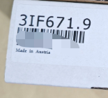

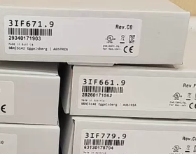
PROFIBUS-DP module d'interface de communication pour le système 2005 série
(Exclusif au système existant 2005 CPU en rack, fin de vie)
- Description de la norme officielle
Système 2005 module d'interface avec 1 Port RS485 isolé galvaniquement prenant en charge le bus de terrain PROFIBUS DP; installé dans le connecteur d'extension IF entre le processeur et les connecteurs d'extension supplémentaires.
- Répartition du code modèle
| Segment | Définition |
| 3SI | Famille de modules d'interface de communication pour Système 2005 |
| 661 | Sous-série d'interface RS485 à isolation galvanique PROFIBUS DP |
| 0.9 | Numéro de révision du matériel |
- Matériel de base & Paramètres électriques (Fiche technique originale)
- Interface de bus
Couche physique: 1 canal RS485 isolé galvaniquement (Conforme PROFIBUS)
Tension de tenue d'isolement: 250 Isolation galvanique V AC pour une immunité CEM améliorée sur site
Connecteur correspondant: 0Terminal de bus PROFIBUS standard G1000.00-090 (accessoire en option)
- Spécifications des communications
Protocole: PROFIBUS-DP (Classe 1 Maître seulement)
Débit en bauds: Plage adaptative de 9.6 kbit/s à 12 Mbit/s
Plage d'adresses de station: 0 ~ 126
Dossier de support: Package de fichiers GSD officiel V1.01 pour 3IF661.9
- Alimentation & Consommation d'énergie
Alimentation: Dérivé du système 2005 bus de fond de panier; pas d'externe 24 Alimentation VCC requise
Consommation électrique typique: 0.4 W
- Évaluations environnementales
Température de fonctionnement: -20 ℃ ~ +60 ℃
Stockage / température de transport: -40 ℃ ~ +85 ℃
Classe de protection: IP20 (montage en armoire uniquement)
Poids: Environ. 0.10 kilos
- Certifications
CE, UKCA, UL cULus, Certifications de contrôle industriel EAC
III. Installation & Instructions de configuration
- Règles de montage en rack
Compatible uniquement avec le système 2005 racks CPU série (3CPxxx, 3Contrôleurs RPxxx)
Position de montage: Premier emplacement d'extension IF sur le côté droit du CPU; Les emplacements IO sont interdits
Quantité maximale par CPU: 1 morceau de 3IF661.9
- Assistance logicielle
Logiciel de programmation: Studio d'automatisation
Version minimale compatible: COMME V4.0 (avec package de mise à niveau matérielle 1.0.0.1)
Éléments configurables: Adresse de la station DP, débit en bauds, mappage des données de processus, activation du diagnostic
- Diagnostic
Module équipé de LED d'état pour l'alimentation, diagnostic de défaut de communication du bus et de déconnexion du bus DP.
- Solutions de remplacement en fin de vie (Système 2005 vers X20)
Solution 1: Remplacement direct au sein de la même architecture (Système de retenue 2005 étagère, approvisionnement en pièces de rechange)
Aucun modèle amélioré compatible dans la même série. Le 3IF661.9 a été officiellement arrêté; seules les pièces de rechange d'occasion/reconditionnées sont disponibles.
Solution 2: Mise à niveau complète du système vers X20 (Recommandé pour les nouveaux projets & rénovations)
| Système d'origine 2005 Module | Modèle de remplacement X20 | Description de la différence |
| 3IF661.9 (Maître PROFIBUS DP RS485 à isolation galvanique) | X20IF1061 | Maître PROFIBUS DP pour racks X20, isolé galvaniquement avec des performances améliorées |
| X20IF1063 | PROFIBUS DP double canal pour les applications de bus redondants |
Notes de remplacement
- Système 2005 les programmes ne peuvent pas être migrés directement vers X20; configuration matérielle, la cartographie et la compilation des bus doivent être retravaillées.
- Les fichiers PROFIBUS GSD sont entièrement compatibles, aucune modification requise pour les appareils esclaves DP.
- Bus de fond de panier, l'alimentation et les dimensions de montage sont totalement incompatibles; remplacement complet du processeur X20 + l'unité de base est obligatoire.
- Scénarios d'application typiques
Machines-outils & machines d'emballage: Système hérité 2005 B&R-automates communiquant avec les onduleurs, servomoteurs et stations DP IO déportées
Modernisation des lignes de production: Extension de la communication par bus PROFIBUS pour équipements vieillissants
Métallurgie, plastique & extension de la capacité de communication de la ligne d'automatisation héritée du textile
- Matrice de dépannage des pannes courantes
| Phénomène de défaut | Cause première | Étapes de résolution |
| LED BUS rouge fixe, aucune communication | Bus DP déconnecté / résistance de terminaison manquante | 1. Vérifier le commutateur DIP de terminaison sur le connecteur de bus 0G1000; 2. Mesurer la continuité des lignes de signaux A/B; 3. Vérifier les adresses de station en double |
| Pas d'éclairage LED après la mise sous tension | Mauvais contact dans l'emplacement du fond de panier | Retirez et réinsérez le module, nettoyer les doigts dorés du fond de panier, tester dans un autre emplacement IF |
| Perte fréquente de paquets de communication | Mauvaise mise à la terre / circuit d'isolation endommagé | Acheminement séparé des câbles de puissance et des câbles de bus DP; remplacer le module 3IF661.9 |
VII. Liste des documents justificatifs (Téléchargeable officiel)
- Fiche technique 3IF661.9 V1.0 (2004 Manuel en anglais)
- Package de mise à niveau matérielle AS V4.0
- Paquet de fichiers de description PROFIBUS GSD V1.01
- 0Manuel de câblage du connecteur de bus G1000.00-090
Tutoriel complet de configuration des paramètres de communication pour B&R 3IF661.9 (Maître PROFIBUS DP System2005)
Conditions préalables
- Contraintes matérielles
Compatible uniquement avec les processeurs rack System2005 (3CPxxx/3RPxxx), installé dans l'emplacement de communication IF à droite du CPU (Slots IO interdits); maximum 1 unité par CPU.
Accessoires pour bus DP: Connecteurs DP standards 0G1000; réglez la résistance de terminaison sur ON pour le premier & derniers nœuds de bus, OFF pour les nœuds intermédiaires.
- Environnement logiciel
Studio d'automatisation V4.0 ~ V4.7 (La bibliothèque matérielle pour System2005 est supprimée dans les versions supérieures à V4.7)
La bibliothèque matérielle complète System2005 doit être chargée; pilote natif pour 3IF661.9 inclus, aucune importation GSD de module séparé n'est nécessaire.
- Préparation du fichier
Fichiers GSD pour tous les appareils esclaves DP (onduleurs, E/S distantes, instruments, etc.)
- Configuration du rack matériel (Vue physique)
- Créez un nouveau projet standard et sélectionnez le processeur 3CP/3RP System2005 correspondant.
- Basculez vers la vue matérielle de la vue physique sur la gauche, faites glisser et déposez le CPU sur le rack.
- Glissez et déposez le module « 3IF661.9 » dans le connecteur d'extension IF à droite du CPU.
> Note: La position de l'emplacement doit correspondre au matériel physique; une erreur de non-concordance matérielle sera déclenchée pendant le téléchargement, sinon.
- Cliquez avec le bouton droit sur 3IF661.9 → Configuration pour ouvrir le panneau des paramètres du maître DP.
- Paramètres des paramètres de communication du maître DP principal (3Configuration IF661.9)
- Paramètres généraux du bus (Onglet Général)
| Élément de paramètre | Règle de valeur | Description |
| Adresse de la gare (Adresse principale) | 1~126, 0 est interdit | Adresse 0 est réservé à la diffusion DP; la station principale doit utiliser une adresse unique 1 à 126 sur l'ensemble du réseau |
| Débit en bauds | 9.6k/19,2k/93,75k/187,5k /500k/1,5M/3M/6M/12M | Limites de longueur de câble: 12M=100m, 1.5M=200m, 500k=400m, 187.5k=1000m; Tous les esclaves doivent adopter un débit en bauds identique à celui du maître |
| Temps de rotation cible | Min.. 2 MS, recommandé 5 ~ 20 ms | Cycle de rafraîchissement des données du bus; cliquez sur 【Ajuster】 pour une optimisation automatique du Token Ring par logiciel |
| Chien de garde des bus | 100~5 000 ms | Seuil de temporisation pour l'alarme en cas de déconnexion du bus/perte de communication; 500 ms recommandé pour les applications sur le terrain |
| Isolement | Fixé 250 V et (matériel câblé, non configurable) | Isolation galvanique intégrée au matériel, aucun ajustement logiciel requis |
- Paramètres avancés de contrôle de bus (Onglet Avancé)
- Nombre de tentatives: Délais de retransmission en cas d'échec de communication; par défaut = 3, s'ajuster à 5 pour les environnements à fortes interférences.
- Facteur d'écart: Écart de jeton DP; garder la valeur par défaut 10.
- Activation du diagnostic: Cochez pour activer les fonctions de diagnostic de l'esclave pour la lecture du code d'erreur via le programme PLC..
- Prise en charge de la synchronisation/gel: Rechercher des scénarios de synchronisation de contrôle de mouvement; décocher pour les applications IO standard.
- Remarque sur le mode de fonctionnement des touches
Le 3IF661.9 agit comme une classe 1 Maître DP, prenant en charge l'échange de données IO cyclique uniquement. Le mode esclave et la communication DX directe entre esclaves ne sont pas pris en charge.
III. Importer des fichiers GSD d'esclave DP & Configurer les esclaves
- Barre de menu supérieure d'AS: 【Outils】 → 【Gestionnaire de périphériques tiers】(Gestionnaire de périphériques tiers)
- Cliquez sur 【Import Fieldbus Devices】 pour importer tous les fichiers esclaves « .gsd ».
- Revenez à la fenêtre de configuration du 3IF661.9 et passez à l'onglet Topologie du bus 【Topologie】.
- Localisez les esclaves DP importés dans la bibliothèque matérielle de gauche, glisser-déposer sur la ligne du bus DP.
- Double-cliquez sur chaque esclave pour attribuer une adresse de station unique (1~126), ne chevauche pas l'adresse principale.
- Double-cliquez sur l'esclave pour accéder à la page de mappage IO; sélectionner la fiche technique du périphérique correspondant à la longueur d'octet d'entrée/sortie.
- Mappage des données du processus IO (Mappage d'E/S – Interface principale du programme API)
- Basculez vers l'onglet 【I/O Mapping】 dans la fenêtre de configuration 3IF661.9.
- DP_In (données reçues des esclaves vers l'automate) & DP_Sortie (commandes de contrôle envoyées de l'automate aux esclaves) les chaînes sont affichées à gauche.
- Liez les variables globales ou de programme comme indiqué ci-dessous:
Consigne de fréquence du variateur: Lier `Program.DP_Out.Freq_Set` à l'octet de sortie esclave 0~1
Retour d'information du courant moteur: Liez `Program.DP_In.Motor_Current` à l'octet d'entrée esclave 2 ~ 3
- Règles de mappage
Définissez la cohérence sur Tout de manière universelle pour éviter un mauvais alignement des données fragmentées.
La longueur maximale d'E/S par esclave unique ne doit pas dépasser 244 octets (Limitation de la norme DP)
- Compilation, Télécharger & Diagnostic des communications
- Télécharger le flux de travail
- Cliquez sur 【Appliquer】 pour enregistrer la configuration du module une fois que tous les paramètres sont définis.
- Construire l'ensemble du projet; télécharger sur le processeur System2005 si aucune erreur matérielle ne se produit.
- Définition de l'état des LED du module
PWR vert fixe: Alimentation du fond de panier normale
BUS vert clignotant: Communication sur le bus DP établie normalement
BUS rouge fixe: Déconnexion du bus / adresse en double / débit en bauds incompatible
ERR rouge fixe: Défaut esclave / longueur de mappage d'E/S incompatible
- Dépannage du diagnostic en ligne
- Ouvrez 【System Diagnostics Manager】 en mode en ligne.
- Filtrer pour afficher le module 3IF661.9:
Compteurs d'émission/réception de paquets de bus
Liste des numéros de station esclave hors ligne/défaut
Expiration du délai de surveillance & Compteurs d'erreurs de communication CRC
- Localisation rapide des défauts
Tous les esclaves hors ligne: Vérifier le débit en bauds, résistances de terminaison et câblage A/B
Esclave unique hors ligne: Vérifiez l'adresse de la station DIP matérielle, Type GSD IO PPO et câblage A/B
- Erreurs de configuration courantes & Éviter les pièges
- Insertion incorrecte de l'emplacement: L'installation de 3IF661.9 dans l'emplacement IO déclenche une erreur matérielle lors du téléchargement.
- Adresse de la station en double: Adresse principale = 1; les esclaves ne peuvent pas utiliser l'adresse 1; adresse 0 ne doit être attribué à aucun appareil.
- Débit en bauds incompatible: Tout esclave avec un débit en bauds incohérent entraînera une LED BUS rouge fixe et une perte totale de communication.
- Version GSD manquante/mauvaise: Les esclaves ne peuvent pas être ajoutés ou la table de mappage IO est vide; réimporter le fichier GSD du fabricant d'origine.
- Temps de cycle trop court: Temps de rotation cible < 2 ms provoque de fréquentes pertes de paquets et des alarmes de bus.
- Caractères chinois dans le chemin du projet: Échec de l'importation GSD & erreur de compilation; seulement l'anglais & chiffres autorisés dans les chemins de fichiers.
VIII. Référence supplémentaire sur la migration en fin de vie
L'ancien 3IF661.9 monté en rack System2005 ne peut pas être utilisé directement dans les systèmes X20. Modèle de remplacement de mise à niveau recommandé: X20IF1061. La logique de configuration est cohérente, pourtant, le fond de panier et la bibliothèque matérielle sont totalement incompatibles, nécessitant un processeur complet & remplacement de l'unité de base.
Liste complète des B&Modules d'interface de communication R
Classé selon quatre plates-formes matérielles majeures: Système 2005 (3SI, EOL), X20 (X20IF, PLC d'armoire grand public), X67 (X67IF/BC, Contrôleurs de bus d'E/S distants distribués IP67), X90 (X90IF, engins de chantier mobiles). Classé par maître/esclave de bus de terrain, port série et bus Ethernet en temps réel.
- Système 2005 Modules de communication série 3IF (Support hérité, Fin de vie; 3IF661.9 appartient à cette série)
Règle de dénomination: `3IFxxx.9` = Module de communication à connecteur d'extension IF pour System2005; suffixe `.6`/`.86` pour les premières révisions matérielles.
- En série / Modules série mixtes
| Modèle | Spécifications de l'interface | Application |
| 3IF613.9 | 3 ports RS232 isolés galvaniquement | Lecteurs de codes-barres, instruments, communication série de l'imprimante |
| 3IF621.9 | 1 RS485/422 isolé galvaniquement + 1 Port CAN | Communication série personnalisée + CANopen |
| 3IF622.9 | 1 RS232 + 2 Ports RS485/422 isolés galvaniquement | Interconnexion de périphériques série multicanaux |
- Série de bus CAN
| Modèle | Spécifications de l'interface | Application |
| 3IF671.9 | RS232 + RS485 + 1 Port CAN | Série mixte & Extension CAN |
| 3IF672.9 | RS232 + 2 ports CAN isolés galvaniquement | Maître CANopen double canal |
- Série PROFIBUS-DP (Votre module actuel)
| Modèle | Spécifications de l'interface | Mode de fonctionnement |
| 3IF661.9 | 1 Port RS485 DP isolé galvaniquement | Classe 1 DP Master exclusif aux racks System2005 |
| 3IF762.9 | RS485 + Esclave DP V0 | Carte d'extension aPCI esclave DP pour emplacement aPCI intégré au processeur |
- Ethernet / Ethernet temps réel POWERLINK
| Modèle | Spécifications de l'interface | Fonction |
| 3IF681.86 / 3IF681.95 / 3IF681.96 | 1Port Ethernet RJ45 ×10M | IHM TCP/IP standard & communication informatique supérieure |
| 3IF686.9 | POWERLINK V1/V2 à isolation galvanique | Maître de contrôle de mouvement POWERLINK |
- Cartes de communication d'extension aPCI (3IF7xx, Emplacement aPCI interne du processeur)
3IF722.9 (Ports série multicanaux), 3IF761.9 (Maître DP), 3IF789.9-1 (LIEN PUISSANT + Maître de liaison X2X)
- Modules de communication X20IF série X20 (PLC d'armoire grand public actuel, Remplacement de la migration System2005)
Règle de dénomination: Module à bus unique `X20IF1xxx`; Module double bus mixte `X20IF2xxx`.
- Communication série RS232/485
X20IF1020: 1 Port RS232/422/485 isolé galvaniquement
X20IF1030: 2 ports RS485 indépendants à isolation galvanique
- Série PROFIBUS-DP (3Options de remplacement IF661.9)
| Modèle | Mode | Description |
| X20IF1061 | Maître DP V1 | Maître DP monocanal, remplacement supérieur pour 3IF661.9 |
| X20IF1063 | Esclave DP V1 | L'automate agit comme un esclave DP communiquant avec un maître tiers |
| X20IF1063-1 | Esclave DP avec prise en charge du diagnostic DTM | Version améliorée pour la mise en service des équipements & dépannage |
| X20IF1063-2 | Esclave DP redondant double canal | Applications d'architecture de bus redondante |
- PEUT / CANopen
X20IF1072: Port maître CAN isolé galvaniquement unique
X20IF2792: 1 Port CAN + 1 Lien X2X (bus d'extension d'E/S distantes)
- Bus de mouvement en temps réel POWERLINK
X20IF1082: POWERLINK monocanal avec hub 2 ports intégré, prise en charge de la redondance en anneau
X20IF1082-2: Équipé d'une synchronisation haute vitesse PRC (contrôle synchrone multi-axes)
X20IF1086-2: POWERLINK à fibre optique pour les environnements longue distance très bruyants
- PROFINET E/S
X20IF10E3-1: Périphérique PROFINET IO (Esclave)
X20IF10E1: Contrôleur PROFINET IO (Maître)
- Bus d'extension d'E/S distantes X2X Link
X20IF2772: Maître de liaison X2X, variateurs X67 modules IP67 distribués
III. Série X67: Unités de communication d'E/S distantes distribuées IP67
Deux catégories: Contrôleurs de bus X67BC, Modules série X67IF
- Contrôleurs de bus X67BC (Canaux IO intégrés, connexion directe au bus de terrain)
X67BC4321: Contrôleur de bus CANopen
X67BC5321: Contrôleur de bus DeviceNet
X67BC6321: Contrôleur de bus PROFIBUS DP; le suffixe .L08/.L12 correspond aux connecteurs M8/M12
X67BC7321: Contrôleur de bus CAN IO
X67BC8321-1: Contrôleur de bus POWERLINK
- Modules de communication série autonomes X67IF (Montage sur site IP67 pour scanners & instruments)
X67IF1121-1: RS232/RS485 combiné avec 2DI intégré + 2FAIRE des chaînes numériques
- Plateforme de contrôle mobile X90 Cartes d'extension X90IF (Machines de construction, Contrôleurs de véhicules)
X90IF730.04-00: 3 Ports CAN + 1 Port RS485 dédié aux équipements mobiles
Cartes d'extension générales X90IF: Soutien PEUT, RS485 et Ethernet; PROFIBUS/PROFINET non pris en charge
- Règles de décodage du code modèle universel (Identification rapide des fonctions)
- Préfixe de plateforme
3SI = Système2005 (Support hérité, Fin de vie)
X20IF = Module de communication API d'armoire X20 (Grand public actif)
X67BC = Contrôleur de bus distant IP67; X67IF = Module série IP67
X90IF = Carte d'extension de contrôleur de machines de construction mobiles
- Identifiant de bus à mi-chiffre
66x = PROFIBUS-DP
67x = Bus CAN
62x = Port série RS485/232
68x = Ethernet / LIEN PUISSANT
1061/1063 = X20 PROFIBUS
108x = X20 POWERLINK
- Code de révision du suffixe
.9 / .6 = Révision matérielle System2005
-1 / -2 = Version à fonctions améliorées X20/X67 (Redondance, Fibre Optique, Diagnostic avancé)
- Référence de remplacement multiplateforme pour 3IF661.9 (Aide-mémoire pour la sélection des rénovations)
| Module de fin de vie d'origine | Modèle de remplacement amélioré | Remarque sur la migration de la plateforme |
| 3IF661.9 (Maître DP System2005) | X20IF1061 | Processeur X20 complet & remplacement du rack requis; Protocole DP entièrement compatible, Fichiers GSD réutilisables |





NH42-63-318x560.png "Commutateurs de transfert automatiques de type PC CHINT (ATS)NH42-63/4SZ")



