 Contacteur,disjoncteur,capteur,Encodeur,API,Convertisseur

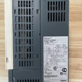
Interprétation complète du modèle
| Segment de modèle | Description |
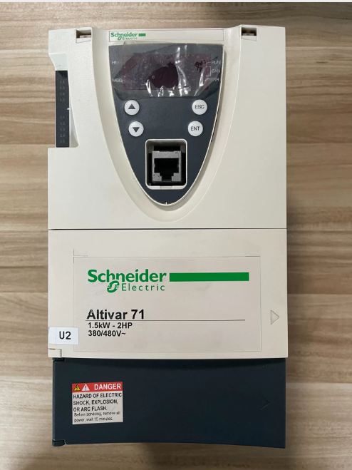
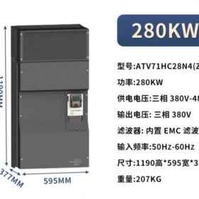
| ATV71 | Série de produits: Schneider Altivar 71 haute performance convertisseur de fréquence, conçu pour les complexes, équipement mécanique de grande puissance, remplaçant principalement la série ATV58/68 |
| H | Classe de tension: Triphasé 380~480V (50/60Hz) |
| C | Type de demande: Application à couple constant, adapté aux scénarios à couple élevé tels que le levage, levage, et manutention du matériel |
| 28 | Code d'alimentation: Correspondant à une puissance nominale moteur de 280 kW (certains documents indiquent une compatibilité avec les moteurs de 315 kW) |
| N4 | Configuration standard: Filtre CEM de classe B intégré, Classe de protection IP20, pas d'unité de freinage intégrée |
| (Z) | Identifiant spécial: IndiqueÉcouterpas de terminal graphique intégré, uniquement équipé d'un panneau de commande de base |
- Paramètres techniques de base
| Élément de paramètre | Valeur | Remarques |
| Tension d'entrée nominale | Triphasé 380~480V, 50/60Hz | Plage de fluctuation autorisée: -15%~+10% |
| Puissance de sortie nominale | 280kW (compatible avec les moteurs de 315 kW) | Valeur nominale pour les applications à couple constant |
| Courant de sortie nominal | 550UN | Courant de sortie continu à une fréquence porteuse de 2,5 kHz |
| Courant de sortie instantané | 825UN (pour 60 secondes) | 150% du courant nominal, adapté aux démarrages intensifs |
| Fréquence de sortie maximale | 600Hz | Répond aux exigences de contrôle des moteurs à grande vitesse |
| Modes de contrôle | V/F en boucle ouverte, contrôle vectoriel (facultatif) | Prend en charge plusieurs algorithmes de contrôle de moteur pour différents scénarios d'application |
| Composants intégrés | Filtre CEM classe B, panneau de commande de base | La version Z n'a pas de terminal graphique; le terminal graphique VW3A1101 doit être acheté séparément |
| Classe de protection | IP20 | Convient pour une installation à l'intérieur d'armoires de commande électrique |
| Accessoires recommandés | Disjoncteur NSX630, Le contacteur LC1F630 est recommandé | Assurer le fonctionnement sécuritaire du système électrique |
III. Caractéristiques principales du produit
- Performances de couple élevées: Spécialement conçu pour les charges à couple constant, avec un couple de démarrage allant jusqu'à 150% du couple nominal, idéal pour les équipements nécessitant un couple de sortie stable, tels que les grues, ascenseurs, et bandes transporteuses
- Fonctions de contrôle flexibles: Prise en charge 8 vitesses prédéfinies, Régulateur PID, et logique de commande de frein pour répondre aux exigences complexes de contrôle de mouvement
- Capacité de communication intégrée: Interfaces de communication Modbus et CANopen intégrées; prise en charge des réseaux industriels tels que Profibus et Ethernet via des cartes d'extension
- Mécanisme de protection global: Équipé de fonctions de protection complètes, y compris les surintensités, surtension, sous-tension, surchauffe, court-circuit, et protection contre les défauts à la terre, protégeant efficacement le variateur de fréquence et le moteur
- Entretien facile: Fonctions de diagnostic intégrées pour une localisation rapide des défauts; la conception modulaire facilite la réparation et le remplacement des composants
- Scénarios d'application et équipements compatibles
- Principaux domaines d'application:
Machines de levage: Ponts roulants, grues à tour, grues portuaires, etc..
Équipement de levage: Ascenseurs, escaliers mécaniques, treuils de mine, etc..
Manutention des matériaux: Convoyeurs à bande, élévateurs à godets, convoyeurs à vis, etc..
Autres équipements à couple élevé: Machines d'emballage, machines à bois, équipement de charge à haute inertie
- Ne convient pas pour:
Applications à couple variable de type charge légère ou ventilateur/pompe (la série ATV71D est recommandée)
Installation extérieure non protégée (des enceintes de protection supplémentaires sont nécessaires)
Scénarios nécessitant des freinages fréquents (les unités de freinage externes doivent être configurées séparément)
- Précautions de sélection et d'utilisation des clés
- Différenciation des modèles:
ATV71HC28N4: Equipé d'un panneau de commande de base, pas de terminal graphique
ATV71HC28N4Z: Marqué explicitement sans terminal graphique, avec la même configuration que le modèle ci-dessus
ATV71HD28N4: Version à couple constant avec terminal graphique
- Exigences d'installation:
Doit être installé à l'intérieur d'une armoire de commande électrique avec classe de protection IP20
Un espace de dissipation thermique suffisant doit être réservé (plus de 100 mm de tous les côtés: haut, bas, gauche et droite)
Une self d'entrée est recommandée du côté de l'entrée pour réduire les interférences harmoniques.
- Achat d'accessoires:
Terminal d'affichage graphique: VW3A1101 (applicable aux modèles sans l'identifiant Z)
Unité de freinage: VW3A3520 (applicable aux scénarios nécessitant des freinages fréquents)
Cartes d'extension de communication: VW3A3306 (Profibus-DP), VW3A3310 (Ethernet), etc..
- Statut du produit Description
Ce modèle a été abandonné en mars 31, 2020. Schneider recommande la série ATV930 comme produit de remplacement (modèle ATV930C28N4Z), qui comporte des algorithmes de contrôle plus avancés, efficacité énergétique supérieure, et des fonctions de communication plus complètes.
Installation, Guide de câblage et manuel de dépannage pour Schneider ATV71HC28N4(Z) Convertisseur de fréquence
- Directives d'installation clés
1.1 Préparation avant l'installation
Conditions préalables de sécurité: Exploité uniquement par des électriciens certifiés. Débranchez toutes les alimentations avant l'installation et attendez 15 minutes pour permettre aux condensateurs du bus DC de se décharger complètement (tension < 45Vcc)
Exigences environnementales:
Température: -10°C à +40°C (déclasser par 1% pour chaque augmentation de 1°C au-dessus de 40°C)
Humidité: 5%-95% sans condensation
Altitude: ≤1000m (déclasser par 1% pour chaque augmentation de 100 m au-dessus de 1 000 m)
Classe de protection: IP20 (pose d'armoire), assurer une bonne aération
Préparation des outils: Multimètre, 1000V mégohmmètre, clé dynamométrique, outil de sertissage, ruban isolant
1.2 Installation mécanique
Méthode d'installation: Doit être installé verticalement, avec un espace de dissipation thermique de 150 mm réservé de tous les côtés (haut, bas, gauche et droite)
Exigences de correction: Fixez avec des boulons M12 à une valeur de couple de 50 Nm pour garantir la stabilité et l'absence de vibrations
Circuit de refroidissement:
Equipé d'un ventilateur de refroidissement intégré; assurez-vous que les entrées d’air ne sont pas obstruées
Nettoyer régulièrement la poussière dans le conduit d'air (chaque 3 mois)
Installer un équipement de refroidissement externe lorsque la température ambiante dépasse 40°C
1.3 Connexion électrique (Étapes principales)
| Borne de connexion | Fonction | Exigences de connexion |
| R/L1, S/L2, T/L3 | Puissance d'entrée triphasée (380-480V) | 1. Connectez-vous au disjoncteur NSX630 (recommandé) |
| 2. Câble à âme en cuivre avec section transversale ≥240 mm² | ||
| 3. Valeur de couple: 60Nm | ||
| U, V, W | Sortie triphasée (connecté au moteur) | 1. Câble à âme en cuivre avec section transversale ≥240 mm² |
| 2. Puissance du moteur ≤315kW | ||
| 3. Valeur de couple: 60Nm | ||
| 4. Longueur de câble ≤100m (aucun filtre requis) | ||
| Pennsylvanie, PC | Bornes de bus CC | 1. Connectez-vous au réacteur DC intégré |
| 2. L'alimentation externe est interdite | ||
| PO, PC | Bornes de la résistance de freinage | 1. Connectez-vous uniquement lorsqu'un freinage rapide est requis |
| 2. Puissance de la résistance de freinage ≥15kW | ||
| +24V, GND | Alimentation de contrôle | 1. Connectez-vous à l'alimentation 24 V CC. |
| 2. Câble à âme en cuivre avec section transversale ≥2,5 mm² | ||
| AI1-AI2 | Entrée analogique | 1. Connecté avec un câble blindé |
| 2. Couche de blindage mise à la terre à une extrémité | ||
| DI1-DI6 | Entrée numérique | 1. Contact sec ou signal PNP/NPN |
| 2. Câble à âme en cuivre avec section transversale ≥1,5 mm² | ||
| DO1-DO3 | Sortie numérique | 1. Sortie relais (250VCA/30 VCC) |
| 2. Courant maximal: 5UN | ||
| PE | Mise à la terre de protection | 1. Câble à âme en cuivre avec section transversale ≥95 mm² |
| 2. Doit être connecté à la barre de mise à la terre du système | ||
| 3. Valeur de couple: 60Nm |
Notes de connexion:
- Acheminer les câbles d'entrée et de sortie séparément (distance ≥300mm) pour éviter les interférences électromagnétiques
- Utiliser des câbles blindés pour les circuits de commande, avec la couche de blindage mise à la terre à une extrémité (du côté du variateur de fréquence)
- Effectuez un test de traction sur toutes les connexions des bornes pour garantir l'absence de jeu.
- Installer un limiteur de surtension côté moteur (facultatif)
1.4 Câblage du circuit de commande
Circuit de contrôle de base:
Connectez le démarrage (DI1), arrêt (DI2), et avant/arrière (DI3) bornes
Assurez-vous que le circuit d'arrêt d'urgence est indépendant de la commande du variateur de fréquence.
Connexion de communication:
Modbus: Se connecte aux bornes RS485 (+, -) avec un débit en bauds de 9600-19200bps
Profibus: Installez la carte de communication VW3A3407 en option
- Processus d’inspection et de mise en service du câblage
2.1 Inspection du câblage
- Test d'isolation:
Résistance d'isolement entre les bornes d'entrée/sortie et la terre ≥1MΩ (testé avec un mégohmmètre 1000V)
Résistance d'isolation de l'enroulement du moteur ≥1MΩ
- Test de continuité:
Vérifiez qu'il n'y a pas de court-circuit entre les bornes d'entrée et de sortie
Vérifier la continuité normale des bornes du circuit de commande
- Paramétrage:
Restaurer les paramètres d'usine (P0,01=1)
Définir les paramètres du moteur (P1.01-P1.07): puissance nominale, tension, actuel, fréquence
Définir le mode de contrôle (P2.01=0: Contrôle V/F; =1: contrôle vectoriel)
2.2 Étapes de mise en service
- Mise en service à vide:
Débrancher le moteur, démarrer le convertisseur de fréquence, et vérifiez la tension de sortie équilibrée
Testez la plage de réglage de la fréquence (0-60Hz)
- Mise en service chargée:
Connecter le moteur, régler le temps d'accélération (P4.01=10s) et temps de décélération (P4.02=15s)
Chargez progressivement jusqu'à 100% et vérifiez le courant et la température normaux
Capacité de surcharge de test (150% du courant nominal pour 60 secondes)
- Manuel de dépannage
2.1 Processus de diagnostic des pannes
- Identification des défauts: Enregistrer les codes d'erreur, état de fonctionnement au moment du défaut, et réglages des paramètres
- Inspection préliminaire:
Éteignez et vérifiez les câbles desserrés et les dommages à l'isolation.
Inspecter le système de refroidissement et la poussière dans le conduit d'air
Mesurer la tension d'alimentation et l'isolation du moteur
- Dépannage ciblé: Identifier les causes en fonction des codes d'erreur
- Mise en œuvre de solutions: Réparer ou remplacer les composants défectueux
- Test de vérification: Effectuer un essai de fonctionnement après l'élimination du défaut pour confirmer l'absence d'anomalies
2.2 Codes d'erreur courants et solutions (Contenu de base)
| Code d'erreur | Type de défaut | Causes possibles | Solutions |
| SCF1 | Court-circuit moteur | 1. Court-circuit de l'enroulement du moteur | 1. Tester l'isolation du moteur avec un mégohmmètre |
| 2. Dommages au câble de sortie | 2. Inspecter les câbles et remplacer les pièces endommagées | ||
| 3. Dommages au module IGBT | 3. Exécuter un test de transistor (Menu 1.10) | ||
| 4. Remplacer le module IGBT | |||
| SCF2 | Court-circuit à la terre | 1. Mise à la terre du moteur ou du câble | 1. Vérifier la résistance de mise à la terre du moteur ≥1MΩ |
| 2. Mise à la terre interne du variateur de fréquence | 2. Tester l'isolation entre les bornes de sortie et la terre | ||
| 3. Remplacer les composants endommagés | |||
| OCF | Surintensité | 1. Changement de charge soudain | 1. Prolonger le temps d'accélération (P4.01) |
| 2. Temps d'accélération trop court | 2. Inspecter la charge et éliminer les défauts mécaniques | ||
| 3. Paramètres moteur incorrects | 3. Reconfigurer les paramètres du moteur | ||
| 4. Vérifier le circuit de détection de courant | |||
| OLF | Surcharge du moteur | 1. La charge dépasse la valeur nominale | 1. Réduire la charge ou fonctionner à capacité réduite |
| 2. Paramètres de protection thermique du moteur incorrects | 2. Régler le courant thermique du moteur correctement (ITH) | ||
| 3. Mauvaise dissipation de la chaleur | 3. Nettoyer le conduit d'air et améliorer la dissipation thermique | ||
| 4. Inspecter le ventilateur de refroidissement du moteur | |||
| OHF | Surchauffe du convertisseur de fréquence | 1. Température ambiante trop élevée | 1. Améliorer la ventilation et réduire la température ambiante |
| 2. Dommages au ventilateur | 2. Inspecter le ventilateur et remplacer les pièces endommagées | ||
| 3. Obstruction des conduits d'air | 3. Nettoyer la poussière du conduit d'air | ||
| 4. Vérifier le capteur de température | |||
| USF | Sous-tension | 1. Tension d'entrée inférieure à 340 V | 1. Vérifiez la tension du réseau et installez un stabilisateur de tension si nécessaire |
| 2. Dommages à la résistance de précharge | 2. Inspecter le circuit de précharge | ||
| 3. Fluctuation de l'alimentation électrique | 3. Prolonger le temps de pré-charge | ||
| 4. Remplacer la résistance endommagée | |||
| OSF | Surtension | 1. Tension d'entrée supérieure à 480 V | 1. Vérifier la tension du réseau |
| 2. Temps de décélération trop court | 2. Prolonger le temps de décélération (P4.02) | ||
| 3. Défaut unité de freinage | 3. Inspecter l’unité de freinage et la résistance | ||
| 4. Activer la fonction de suppression de tension | |||
| PHF | Perte de phase d'entrée | 1. Perte de phase dans l'alimentation d'entrée | 1. Vérifier l'équilibre des tensions triphasées |
| 2. Défaut disjoncteur | 2. Inspecter le disjoncteur et le contacteur | ||
| 3. Défaut contacteur d'entrée | 3. Remplacer les composants endommagés | ||
| 4. Vérifier les réglages des paramètres LCF | |||
| EnF | Défaut d'encodeur | 1. Connexion de l'encodeur lâche | 1. Inspecter le câblage de l'encodeur |
| 2. Dommages à l'encodeur | 2. Test du signal du codeur | ||
| 3. Paramètres de paramètres incorrects | 3. Reconfigurer les paramètres du codeur | ||
| 4. Remplacer l'encodeur |
2.3 Dépannage avancé
Défauts de paramètres:
Quand “Paramètre invalide” est affiché, appuyez deux fois sur la touche ENT pour restaurer les paramètres d'usine
Lorsque les paramètres sont corrompus, restaurer les paramètres d'usine via P0.01=1
Défauts de communication:
Vérifiez le câble de communication et les connecteurs desserrés
Confirmez que les paramètres de débit en bauds et d'adresse correspondent au système hôte
Tester le module de communication et remplacer les modules défectueux
Défauts matériels:
Défaut du module d'alimentation: Mesurer la tension du bus CC (plage normale: 540-600V)
Défaut de la carte de commande: Inspecter les voyants et remplacer le tableau de commande si nécessaire
Défaut de la carte pilote: Remplacer la carte pilote et effectuer la remise en service
III. Calendrier d'entretien
| Cycle d'entretien | Contenu de maintenance | Remarques |
| Tous les jours | Vérifier l'état de fonctionnement, paramètres, et la température | Enregistrez toute anomalie |
| Hebdomadaire | Nettoyer la poussière de surface et inspecter les ventilateurs de refroidissement | Assurez-vous que les ventilateurs fonctionnent normalement |
| Mensuel | Vérifiez le câblage et l'isolation des câbles desserrés | Effectuer un contrôle de couple sur les connexions des bornes |
| Trimestriel | Nettoyer la poussière dans le conduit d'air et inspecter la résistance de l'isolation | Utiliser de l'air comprimé pour le nettoyage de la poussière |
| Annuel | Inspection complète et remplacement des pièces d’usure (les fans, condensateurs) | Doit être réalisé par du personnel professionnel |
| Biennal | Test de performances des condensateurs et mise en service complète de la machine | Remplacer les condensateurs si nécessaire |





NH42-63-318x560.png "Commutateurs de transfert automatiques de type PC CHINT (ATS)NH42-63/4SZ")



