 Contattore,interruttore automatico,sensore,Codificatore,PLC,Convertitore

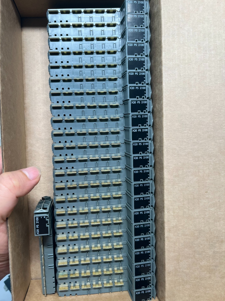

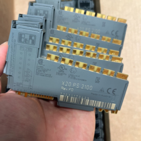
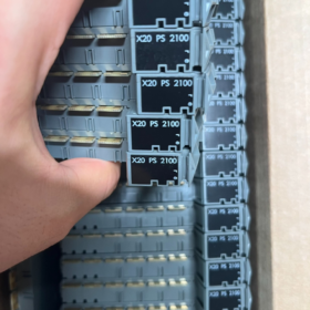
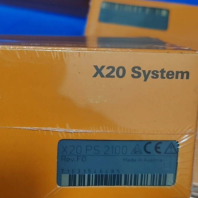
B&RX20PS2100 Manuale di installazione (Versione ingegneristica, compilato per funzionario B&Manuale del sistema R X20)
Modello: X20PS2100; Variante rivestita conforme: X20cPS2100
Modello completo: X20PS2100 (Versione rivestita conforme: X20cPS2100)
Funzione: I/O interni modulo di alimentazione per il sistema X20
✅ Fornisce alimentazione solo all'elettronica I/O interna sul segmento backplane
❌ NON fornisce alimentazione al bus X2X Link (Distinzione critica)
Spiegazione semplice: Alimenta i circuiti elettronici dei moduli DI/DO/AI/AO sul segmento del backplane locale; non è in grado di fornire alimentazione tra i segmenti per l'espansione del bus X2X
- Specifiche elettriche principali
| Articolo | Parametro |
| Tensione in ingresso | 24 VCC, tolleranza -15% ~ +20% |
| Corrente di immissione massima | 10 UN (circuito esterno) |
| Consumo energetico del modulo | Lato autobus: 0.2 W; Circuito I/O: 0.6 W |
| Isolamento elettrico | Nessun isolamento galvanico tra alimentazione I/O e backplane |
| Protezione da cortocircuito | Nessun fusibile integrato. Il fusibile del circuito esterno è obbligatorio |
| Protezione della custodia | IP20 |
| Binario di montaggio | 35 Guida DIN da mm, larghezza del modulo 12.5 mm |
Valutazioni della temperatura ambiente
Montaggio orizzontale: -25 ℃… +60 ℃
Montaggio verticale: -25 ℃… +50 ℃
Elevazione sopra 2000 M: Declassare la temperatura ambiente massima di 0.5 ℃ al 100 M
- Accessori coordinati obbligatori (Ordinato separatamente)
- Modulo autobus (Selezionane uno)
X20BM01: Modulo bus di alimentazione, senza interruttore dell'indirizzo del nodo
X20BM05: Modulo bus di alimentazione, con interruttore dell'indirizzo del nodo X2X
Funzione: Blocca la trasmissione di potenza al backplane sinistro per l'alimentazione segmentata
- Morsettiera: X20TB12 (12-spillo, 24 Terminale con chiave VDC)
- Confronto con i moduli di alimentazione peer (Chiave per la selezione)
| Modello | Obiettivo dell'alimentazione | Supporta l'alimentazione del bus di collegamento X2X | Applicazione tipica |
| X20PS2100 | Solo I/O interno | ❌ Non supportato | Alimentazione segmentata per I/O locali su macchine standalone, backplane corti |
| X20PS3300 | I/O interni + Bus di collegamento X2X | ✅ Supporta l'espansione trasversali | Stazioni remote distribuite, reti X2X Link multisegmento |
⚠️ Errore comune: Tentativo di pilotare i moduli di espansione X2X utilizzando X20PS2100 → Il sistema non funzionerà. È necessario utilizzare X20PS3300.
- Definizione dell'indicatore LED
CORRERE (Verde): Acceso fisso = Modulo normale; SPENTO = Nessuna alimentazione 24V / Colpa
ERR (Rosso): SU / Lampeggiante = Alimentazione anomala, sovraccarico, guasto al cablaggio
- Cablaggio & Linee guida di ingegneria
- I terminali accettano +24V / 0Alimentazione V per alimentare l'attuale segmento del backplane;
- X20BM01/X20BM05 blocca l'alimentazione a sinistra, consentendo l'alimentazione segmentata indipendente per più moduli per mitigare la caduta di tensione;
- Protezione esterna consigliata: Massimo. 10 Un fusibile ad azione lenta;
- La sostituzione a caldo non è supportata;
- È possibile collegare più moduli X20PS2100 in parallelo su un segmento del backplane per aumentare la corrente di alimentazione disponibile.
- Certificazioni
CE, UL cULus, ATEX Zona2, Classe I Div.2 (adatto per aree pericolose Zona2), DNV, Omologazione marina ABS, KC
- Scenari applicativi tipici
Stazioni I/O locali per macchine utensili, linee di confezionamento, macchine per lo stampaggio ad iniezione; alimentazione segmentata per stazioni locali X20 su apparecchiature medio-piccole senza espansione trasversale X2X.
- Risoluzione dei problemi rapida
- LED FUNZIONAMENTO SPENTO: Esterno mancante 24 VCC, Terminali X20TB12 sciolti, polarità di alimentazione invertita
- Il LED ERR è acceso fisso: Cortocircuito nel backplane, sovracorrente oltre il limite
- I moduli parziali non riescono ad accendersi: Controllare l'orientamento di X20BM01/X20BM05, verificare la logica di potenza segmentata
Se necessario, Posso fornire:
Assegnazione completa dei pin di X20TB12
Schema testuale del cablaggio del backplane segmentato standard
Pagine chiave estratte dalla scheda tecnica ufficiale dell'X20PS2100
Oppure valuta se per la tua applicazione è necessario l'aggiornamento a X20PS3300.
Definizione della funzione: Modulo di alimentazione I/O interno del sistema X20 (fornisce alimentazione solo ai circuiti I/O del backplane locale, L'alimentazione del bus X2X Link non è supportata)
⚠️ Nota importante: B&R NON pubblica un manuale di installazione autonomo indipendente per X20PS2100. Le specifiche pertinenti sono documentate nel Manuale dell'utente del sistema X20. Questo documento è standardizzato per la messa in servizio in loco e la progettazione dell'armadio.
Sommario
- Istruzioni di sicurezza pre-installazione
- Elenco dei componenti corrispondenti obbligatori
- Specifiche di installazione meccanica
- Regole di layout del backplane (Critico: frequente fonte di errori)
- Pinatura terminale X20TB12 & Specifiche di cablaggio
- Diagnosi dello stato dei LED
- Specifiche elettriche & Condizioni ambientali
- Selezione del fusibile & Linee guida per la messa a terra
- Procedure standard di messa in servizio all'accensione
- Matrice di diagnosi dei guasti
- Selezione & Tabù di installazione
- Istruzioni di sicurezza pre-installazione
- Tutte le operazioni di installazione e smontaggio devono essere eseguite con 24 Alimentazione VCC scollegata. La sostituzione a caldo NON è supportata.
- I moduli hanno un grado di protezione IP20 e devono essere installati solo all'interno di quadri elettrici.
- Implementare la protezione ESD (indossare un cinturino da polso antistatico) prima di maneggiarlo per evitare danni elettrostatici ai circuiti del backplane.
- Vietare severamente l'ingresso con polarità inversa; evitare il superamento della tensione di ingresso 28.8 VCC.
- Non esiste isolamento galvanico tra l'alimentazione I/O e il backplane. Non applicabile ai circuiti di segnale che richiedono isolamento elettrico.
- Il declassamento della temperatura è obbligatorio per altezze di installazione superiori 2000 M.
- Componenti corrispondenti obbligatori (Fornito separatamente, non incluso nel modulo)
| Numero di parte | Descrizione | Note applicative |
| X20BM01 | Modulo bus di alimentazione | Blocca l'alimentazione I/O a sinistra; nessun cambio di nodo, preferito per I/O locale |
| X20BM05 | Modulo bus di alimentazione | Blocca l'alimentazione I/O a sinistra; con interruttore dell'indirizzo del nodo X2X, utilizzato per le stazioni remote |
| X20TB12 | 12-spillo 24 Morsettiera con chiave VDC | Montaggio obbligatorio; X20TB06 non può essere sostituito |
Ricambi opzionali: Strisce di etichette X20, puntalini per cavi per terminali push-in
- Specifiche di installazione meccanica
3.1 Requisiti della guida DIN
Standard 35 Guida DIN TH35 da mm; larghezza del modulo: 12.5 mm
3.2 Orientamento di montaggio & Limiti di temperatura
| Tipo di montaggio | Temperatura operativa | Osservazioni |
| Montaggio orizzontale (Raccomandato) | -25 ℃… +60 ℃ | Etichetta del modulo leggibile in avanti |
| Montaggio verticale | -25 ℃… +50 ℃ | Riservare spazio superiore e inferiore per la dissipazione del calore |
Magazzinaggio / Temperatura di trasporto: -40 ℃ ~ +85 ℃
Umidità relativa: 5%~95%, È vietata la formazione di condensa
Elevazione 2000 M: Ridurre la temperatura ambiente massima di 0.5 ℃ al 100 M
3.3 Passaggi di installazione
- Agganciare il fermo superiore alla guida DIN;
- Premere verso il basso la parte inferiore del modulo finché non si sente un clic che conferma il bloccaggio sicuro;
- Aderire saldamente ai moduli adiacenti per completare l'interconnessione del backplane;
- Rimozione: Sollevare il fermo inferiore verso l'alto e tirare verso l'esterno per estrarre il modulo.
- Regole di layout del backplane (Requisito ingegneristico di base)
✅ Ordine di layout standard (Da sinistra a destra)
"X20BM01 / X20BM05 → X20PS2100 → Moduli I/O DI/DO/AI/AO`
Principio fondamentale
Caratteristiche hardware di X20BM01/X20BM05: Blocca la trasmissione dell'alimentazione I/O a sinistra
→ X20PS2100 alimenta solo tutti i moduli sul lato destro; i moduli a sinistra non ricevono alimentazione da questa unità.
Configurazioni consentite
- Segmento backplane singolo: BM01 + PS2100 + Moduli I/O
- Alimentazione indipendente multisegmento: `BM01+PS2100 + I/O + BM01+PS2100 + I/O` per la riduzione della caduta di tensione
- È possibile collegare in parallelo più moduli X20PS2100 sullo stesso segmento per aumentare la capacità di alimentazione totale.
❌ Errori di layout severamente vietati
- Posizionare PS2100 sul lato sinistro del modulo bus
- Utilizza PS2100 per alimentare i backplane di espansione X2X Link (l'alimentazione dei segmenti trasversali si guasta; È richiesto X20PS3300)
- Omettere X20BM01/X20BM05 direttamente davanti a PS2100, causando diafonia inversa tra i segmenti del backplane
- Assegnazione pin X20TB12 per X20PS2100
Pin attivi tra i terminali 1~12:
| Terminale n. | Definizione del segnale | Descrizione |
| 1 | +24V I/O | Esterno 24 Ingresso positivo VCC |
| 2 | +24V I/O | Terminale positivo parallelo (supporta doppi cavi in entrata) |
| 11 | GND (0V) | Negativo CC esterno |
| 12 | GND (0V) | Terminale negativo parallelo |
Specifiche di cablaggio
- Sezione del cavo: 0.5 ~ 2.5 Fili di rame intrecciati da mm²; puntalini consigliati per terminali push-in
- Instradare i cavi di alimentazione separatamente dai cavi di segnale analogico per ridurre al minimo le interferenze
- NON collegare i carichi dei sensori di campo direttamente a questi terminali. I terminali servono esclusivamente per l'alimentazione del backplane.
- Definizione dei LED del pannello frontale
Due LED sul lato anteriore del modulo: CORRERE (Verde), ERR (Rosso)
| CORRERE | ERR | Descrizione dello stato | Azione correttiva |
| Acceso fisso | SPENTO | Funzionamento normale | Nessuna azione richiesta |
| SPENTO | Qualsiasi stato | Nessuna alimentazione a 24 V, terminali allentati, polarità invertita | Spegnimento, serrare nuovamente il cablaggio e verificare la polarità |
| Acceso fisso | Acceso fisso | Cortocircuito nel backplane / Grave sovraccarico | Spegnere e individuare il punto di cortocircuito rimuovendo i moduli I/O in sequenza |
| Acceso fisso | Lampeggiante intermittente | Sottotensione (sotto 20.4 VCC) | Misura 24 V uscita alimentazione e caduta di tensione sul cavo |
- Specifiche elettriche
Ingresso nominale: 24 VCC; Raggio d'azione: 20.4 VCC ~ 28.8 VCC (-15% ~ +20%)
Corrente di immissione massima: 10 UN
Autoconsumo del modulo: Lato autobus 0.2 W; Circuito I/O 0.6 W
Isolamento: Nessun isolamento galvanico tra alimentazione I/O e backplane
Classe di protezione: IP20
- Fusibile & Specifiche tecniche di messa a terra
- Requisito fusibile esterno obbligatorio
Installare un dispositivo ad azione lenta da ≤10 A (ritardo) fusibile a monte del circuito
❌ Nessun fusibile interno montato nel modulo; il rischio di cortocircuito può danneggiare permanentemente il backplane!
- Raccomandazioni per la messa a terra
Implementare la messa a terra a punto singolo per 24 VCC 0 V; terra di protezione separata dell'armadio (PE) e cablaggio di terra dell'alimentazione.
Per ambienti ad alta interferenza, montare il condensatore del filtro EMC tra 0 V e PE.
- Procedura standard di messa in servizio all'accensione
- Completare l'installazione meccanica e confermare l'interconnessione completa del backplane;
- Collegare i terminali di alimentazione X20TB12 e ricontrollare la polarità;
- Verificare 24 Alimentazione VDC tramite multimetro;
- Chiudere l'interruttore di alimentazione esterno;
- Confermare che il LED RUN sia acceso fisso e il LED ERR spento;
- Eseguire la scansione dell'hardware tramite Automation Studio per verificare che tutti i moduli I/O su questo segmento vengano rilevati normalmente;
- Misurare la tensione di alimentazione del backplane sui moduli remoti per confermare una caduta di tensione accettabile.
- Matrice di diagnosi dei guasti
| Sintomo di guasto | Causa ultima | Soluzione |
| Il LED RUN non si accende | NO 24 fornitura V, terminali allentati, polarità invertita | Spegnimento, stringere nuovamente i terminali e confermare la polarità |
| Il LED ERR è acceso fisso, modulo non funzionante | Cortocircuito nel backplane, Modulo I/O difettoso | Rimuovere i moduli I/O uno per uno per identificare l'unità difettosa |
| I moduli I/O parziali non si accendono | Orientamento errato del modulo BM01, disposizione errata della potenza segmentata | Regola la disposizione; assicurarsi che il modulo bus sia posizionato a sinistra di PS2100 |
| Bassa tensione sui moduli backplane remoti | Carico eccessivo, cavi troppo lunghi | Aggiungi PS2100 extra per l'alimentazione segmentata; aggiornamento a una sezione trasversale del cavo più grande |
| Guasto completo delle stazioni I/O remote X2X | X20PS2100 distribuito in modo errato; non può fornire alimentazione al bus X2X | Sostituire il modulo con X20PS3300 |
- Selezione & Riepilogo dei tabù di installazione
- X20PS2100 non può fornire alimentazione ai collegamenti di espansione X2X. Selezionare X20PS3300 per stazioni remote distribuite.
- X20BM01/X20BM05 non può essere omesso.
- È vietato lo scambio a caldo.
- Non può essere utilizzato come uscita di potenza per sensori e attuatori esterni; solo per l'elettronica interna del backplane X20.
- Per circuiti di sicurezza che richiedono la disconnessione dell'alimentazione I/O, la revisione hardware Rev.F0 o successiva è obbligatoria.
Accesso al manuale originale ufficiale
Scarica il manuale utente del sistema X20 (Documento n.: UM200.440) da B&Sito ufficiale R; sezione 4.27 contiene le specifiche complete di X20PS2100.
Su richiesta posso fornire:
- Definizioni dei terminali pronte per l'importazione diretta in EPLAN
- Schema di cablaggio del backplane basato su testo
- Tabella comparativa completa tra X20PS2100 e X20PS3300 per la selezione
Difetti comuni, Cause profonde & Misure correttive standard per B&Sistema di I/O R X20
Copre il backplane, moduli di potenza (X20PS2100/PS3300), moduli autobus, moduli I/O digitali/analogici, Problemi di espansione del collegamento X2X e riconoscimento di Automation Studio. Classificato in quattro categorie: Difetti hardware, difetti di cablaggio, errori di configurazione, Interferenze EMC.
Hardware applicabile: X20CPU, Controller bus X20BC, Moduli di potenza X20PS, X20DI/DO/AI/AO, Moduli bus X20BM, Stazioni remote X2X
- Guasti relativi all'alimentatore (Più frequente, Soprattutto con X20PS2100)
1.1 I moduli I/O parziali non si accendono, non rilevato in Automation Studio
Sintomo: I moduli anteriori su un segmento del backplane funzionano normalmente, i moduli remoti non si avviano; LED FUNZIONAMENTO SPENTO
Cause tipiche
- X20BM01/X20BM05 installato al contrario o fuori posto, bloccando la trasmissione di potenza
- X20PS2100 supporta solo l'alimentazione I/O del segmento locale; non può alimentare le stazioni remote X2X
- Carico pesante del backplane, cavi sottili che portano alla sottotensione sottostante 20.4 VCC in posizioni remote
- Fusibile esterno bruciato, terminali TB allentati
Azioni correttive
Regola di impaginazione: Modulo bus installato a sinistra del modulo di alimentazione, il potere si propaga verso destra
X20PS3300 è obbligatorio per le stazioni X2X remote
Utilizza più PS2100 per l'alimentazione segmentata su backplane lunghi
1.2 ERR LED rosso acceso fisso sui moduli X20PSxx
Sintomo: RUN LED verde acceso, ERR fisso / lampeggiante
Cause
- Cortocircuito interno del backplane (modulo I/O danneggiato, pin del backplane deformati)
- Sovraccarico transitorio, tensione di alimentazione fuori tolleranza
- Modulo I/O guasto che interrompe l'alimentazione del backplane
Diagnosi: Spegnere e rimuovere i moduli I/O in sequenza da destra a sinistra per individuare l'hardware difettoso.
1.3 LED RUN completamente spento sul modulo di alimentazione
Esterno mancante 24 VCC, polarità invertita sui terminali X20TB12, terminali non completamente agganciati.
- Backplane & Guasti di contatto meccanico
2.4 Caduta intermittente del modulo
Sintomo: Moduli segnalati casualmente come mancanti in Automation Studio; il guasto si verifica dopo la vibrazione dell'armadio o il funzionamento della porta
Cause profonde
- Interconnessione backplane incompleta tra moduli X20 adiacenti
- Guida DIN allentata; la vibrazione provoca un contatto intermittente
- Ossidazione / deformazione dei contatti a molla del backplane dovuta a ripetuti smontaggi
Contromisura: Riposizionare tutti i moduli; ridurre al minimo lo smontaggio frequente in condizioni operative ad alte vibrazioni.
2.5 Modulo singolo non rilevato mentre altri moduli sullo stesso backplane funzionano normalmente
- Connettore backplane danneggiato sul modulo
- Mancata corrispondenza della revisione hardware con la configurazione del progetto
- Guasto hardware interno permanente del modulo
- Errori del bus di espansione remoto del collegamento X2X (Problema comune in loco)
3.6 Perdita completa di comunicazione con tutti i moduli sulla stazione X2X remota
Sintomo: Guasto segnalato per l'intera stazione remota; Errore del bus X2X visualizzato sul controller master
Trigger primari:
- X20PS2100 utilizzato in modo errato sulla stazione remota (impossibile fornire alimentazione al bus X2X)
- Cavo di comunicazione X2X danneggiato; mancanti o duplicati 120 Resistenza di terminazione Ω
- Interruttori dell'indirizzo del nodo duplicati o impostati in modo errato su X20BM05
- Mancante 24 Alimentazione V alla stazione remota
✅Regola standard: Installarne solo uno 120 Resistore di terminazione da Ω a un'estremità del bus X2X
3.7 Frequenti errori di comunicazione X2X, abbandono ciclico della stazione
Quasi sempre indotto da interferenze EMC:
Cavi X2X instradati parallelamente ai cavi delle unità ad alta potenza su lunghe distanze
Punti di messa a terra multipli per quadri elettrici, differenza di potenziale tra 0 V e PE
Filtri mancanti per inverter e servoazionamenti
- I/O digitali (DI / FARE) Difetti tipici
4.8 Ingresso DI inattivo nonostante il segnale valido misurato esternamente
- Tensione di alimentazione del backplane insufficiente
- Mancante / Cablaggio comune COM interrotto per i canali DI
- Il tipo di sensore source/sink non corrisponde alle specifiche del modulo DI
- Canale di ingresso masterizzato
4.9 L'uscita DO non riesce a gestire il carico / permanentemente ACCESO / SPENTO
- Manca l'alimentatore di carico esterno per i moduli DO (Alimentazione backplane ≠ alimentazione attuatore sulla maggior parte dei moduli X20DO)
- Fusibile elettronico di bordo bruciato a causa di un cortocircuito nel canale
- Ciclo di attività eccessivamente lungo che causa un aggiornamento ritardato dell'output
- Nessun diodo di ricircolo montato per carichi induttivi (elettrovalvole), portando alla rottura del canale
4.10 Danni enormi a più canali DO
Alta probabilità: Caduta di sovratensione causata da carichi induttivi senza protezione contro la rotazione libera.
- I/O analogico (AI / AL) Difetti frequenti
5.11 Deriva del segnale AI, letture fluttuanti e instabili
1 Causa ultima: Interferenza elettromagnetica
- Cavi analogici non schermati; schermo messo a terra su entrambe le estremità (lo schermo deve essere messo a terra su un'estremità all'interno dell'armadio)
- Cavi analogici instradati nella stessa canalina dei cavi di alimentazione
Altre cause:
Caduta di tensione eccessiva sull'alimentazione del sensore
Circuito aperto nel loop da 4~20 mA (il modulo solitamente visualizza il valore minimo)
Contatto scadente sui terminali di ingresso della tensione
5.12 Valore AI bloccato al limite superiore o inferiore
Circuito aperto nel circuito da 4~20 mA → lettura prossima al minimo (~4mA);
Cortocircuito sul sensore → lettura prossima al massimo (~20mA).
5.13 L'uscita AO non riesce a raggiungere il setpoint, capacità di guida insufficiente
L'impedenza di carico supera le specifiche del modulo; terminali del cablaggio allentati; alimentazione backplane insufficiente.
- Software & Errori di configurazione di Automation Studio (Facilmente giudicato erroneamente come un guasto hardware)
6.14 Persistente “Mancata corrispondenza del modulo” errore dopo il download del progetto
Sintomo: Hardware installato fisicamente, ma AS segnala la mancata corrispondenza del modulo
Cause:
- Modello errato selezionato nell'albero hardware del progetto
- Revisione hardware del modulo troppo vecchia, incompatibile con il firmware attivo
- Scansione hardware non aggiornata dopo la sostituzione del modulo
6.15 Modulo rilevato normalmente, ma i segnali I/O non si aggiornano
- Indirizzo di mappatura I/O errato
- Elaborazione I/O non abilitata nell'attività assegnata
- Parametro di abilitazione canale disabilitato nella configurazione del modulo (supportato su moduli selezionati)
6.16 Guasti casuali indotti dall'incompatibilità del firmware
Revisione firmware CPU obsoleta e incompatibile con i moduli X20 più recenti; i sintomi includono l'interruzione casuale del modulo e l'instabilità della comunicazione.
- EMC complessa & Guasti legati alla messa a terra (Il più difficile da risolvere)
Caratteristica tipica: Il guasto si verifica in modo casuale; il sistema funziona in condizioni di assenza di carico, gli errori emergono una volta attivati i carichi
- Punti di messa a terra multipli attivi 24 V 0V e PE creano anelli di terra → deriva del segnale analogico, interruzione X2X intermittente
- I cavi di alimentazione non schermati per inverter e servo inducono interferenze sul bus backplane
- Manca l'isolamento in mezzo 24 V forniture di diversi quadri elettrici, generando differenze di potenziale e disturbi della comunicazione
Specifica consigliata: Messa a terra a punto singolo per 24 VCC 0 V; schermatura del cavo messa a terra solo all'interno del quadro elettrico.
- Difetti indotti dall'ambiente
- Condensa → perdita dal backplane, cortocircuiti casuali, esaurimento permanente del modulo
- La temperatura operativa è stata superata (Orizzontale 60 ℃, Verticale 50 ℃) → comportamento anomalo del modulo, ripristino spontaneo
- Contaminazione di polvere e olio sui terminali e sul backplane → contatto scadente
Procedura standard di risoluzione dei problemi a più livelli per la manutenzione in loco
- Verificare tutti gli alimentatori X20PS; confermare 24 VCC entro l'intervallo: 20.4~28,8 V
- Definire l'ambito dell'errore: Guasto del singolo modulo / Intero segmento del backplane / Tutte le stazioni X2X remote
- Guasto all'intero segmento → Ispezionare i moduli di potenza, Disposizione BM, Alimentazione del bus X2X (Distinguere PS2100 e PS3300)
- Guasto a canale singolo → Ispezionare il cablaggio esterno, sensori/attuatori, terminali comuni, protezione contro le sovratensioni del carico
- Guasti intermittenti casuali → Dare priorità all'ispezione della sede meccanica, Interferenze EMC e impianto di terra





NH42-63-318x560.png "Commutatori automatici di tipo PC CHINT (ATS)NH42-63/4SZ")



