 Contattore,interruttore automatico,sensore,Codificatore,PLC,Convertitore

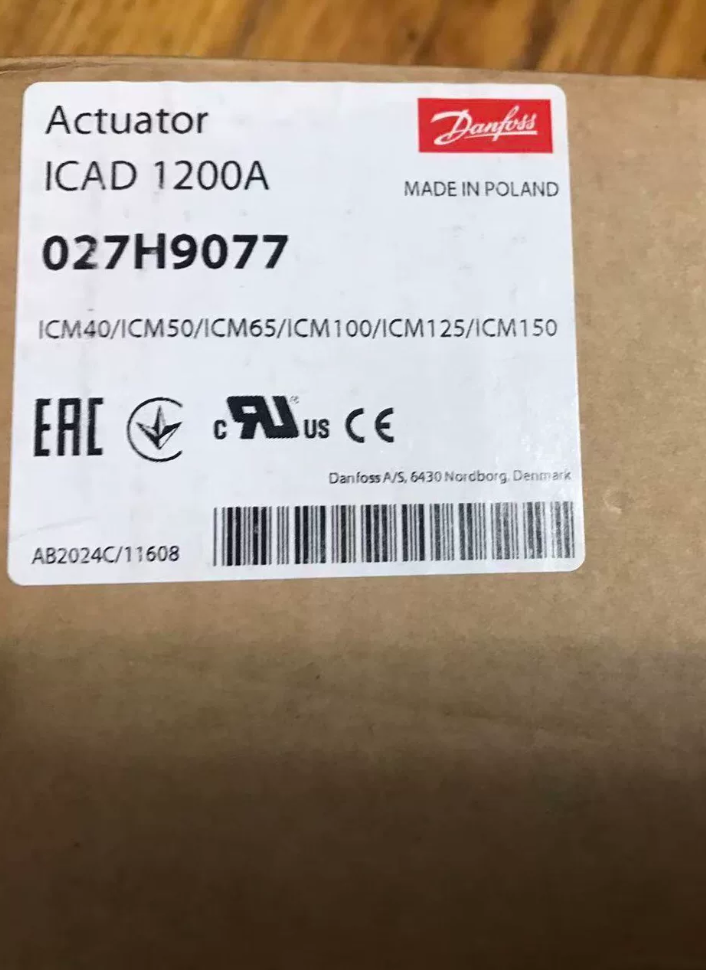
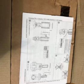
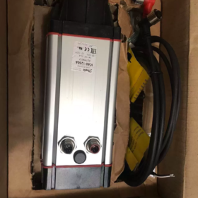
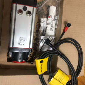
⚠️Nota importante: Il codice articolo 027H9075 corrisponde a ICAD600A (NON ICAD1200A).
Codice articolo ICAD1200A: 027H9077, corrente nominale 2,0 A.
027H9075: ICAD600A, 24 VCC, nominale 1,2 A, compatibile con ICM20-32
027H9077: ICAD1200A, 24 VCC, nominale 2,0 A, compatibile con ICM40-150
- Scomposizione del codice modello
| Numero parte | Modello | Alimentazione elettrica | Corrente nominale | Corpo valvola compatibile |
| 027H9075 | ICAD600A | 24 VCC | 1.2 UN | ICM‑20/25/32 |
| 027H9077 | ICAD1200A | 24 VCC | 2.0 UN | ICM‑40…ICM‑150 |
ICAD = Attuatore con motore passo-passo per valvole motorizzate ICM; VersioneA: codificatore integrato + tastiera MMI LCD locale.
- Parametri elettrici principali (ICAD-1200A 027H9077, 24 V2.0A)
| Articolo | Specifica |
| Alimentazione elettrica | 24 Alimentazione isolata VCC; tolleranza+10%/‑15% (21‑26,4 Vcc) |
| Consumo massimo di corrente | 2.0 UN |
| Alimentatore fail-safe opzionale | 24 UPS VCC / batteria, 2.0 UN |
| Ingresso analogico | 0/4‑20mA (200 OH); 0/2-10 V (10 kΩ) |
| Uscita analogica | 0/4‑20mA, massimo. carico250Ω |
| Ingresso digitale | Controllo ON/OFF passivo con contatto pulito |
| Uscita digitale | 3Uscite a collettore aperto NPN a canale (valvola completamente aperta, completamente chiuso, allarme); 5‑24 V CC esterni richiesti |
| Protezione dall'ingresso | IP67 |
| Temperatura ambiente | ‑30℃~+50℃; condensazione / vietate le condizioni di formazione di ghiaccio |
| Peso | ca. 1,9 kg |
| Interfacce | 2 × connettori circolari M12: 4-alimentazione pin, 8-segnale pin |
- Principio di funzionamento
L'ICAD utilizza un motore passo-passo ad alta velocità con trasmissione senza ingranaggi ad accoppiamento magnetico per azionare la valvola motorizzata ICM. Un encoder di posizione integrato fornisce un feedback sulla posizione della valvola ad anello chiuso.
Funzioni supportate:
- Modulante continua tramite 4-20mA / 2-10 Segnale analogico V.
- Contatto pulito digitale completamente aperto / commutazione completamente chiusa.
- Tastiera LCD locale per l'impostazione dei parametri, indicazione della posizione e lettura del codice guasto.
Design ad accoppiamento magnetico: Nessun collegamento meccanico rigido tra attuatore e corpo valvola; elimina il rischio di perdite di refrigerante.
- Assegnazione dei pin: Connettore di segnale M12-8 pin
| Spillo | Colore del filo | Funzione |
| 1 | Bianco | 24 V CC positivo |
| 2 | Marrone | 24 V CC negativo |
| 3 | Nero | Uscita allarme NPN‑ |
| 4 | Marrone | Uscita completamente aperta NPN‑ |
| 5 | Rosso | Uscita completamente chiusa NPN‑ |
| 6 | Arancia | Segnale GND |
| 7 | Giallo | 4-Ingresso 20 mA (+) |
| 8 | Verde | 2‑Ingresso 10 V / IN Ingresso digitale (+) |
4-connettore di alimentazione M12 pin: Alimentazione principale 24 V CC; connessione opzionale per alimentazione UPS a prova di guasto.
- Elenco valvole compatibili
ICAD600A (027H9075): ICM-20, ICM-25, ICM-32
ICAD1200A (027H9077): ICM-40, 50, 65, 80, 100, 125, 150; adatto anche per valvole pilota CVE.
- Scenari applicativi tipici
Refrigerazione industriale, refrigerazione ad ammoniaca, Unità di refrigerazione transcritica a CO₂
Regolazione elettronica dell'espansione della linea del liquido
Pressione di aspirazione / regolazione della temperatura
Bypass del gas caldo & controllo dello sbrinamento a gas caldo
Grandi impianti frigoriferi, stazioni di compressione frigorifera, linee di congelamento per la lavorazione degli alimenti
Insidie della selezione & Avvertenze sui rischi
- Non confondere i codici articolo: 027H9075=600A (1.2 UN); 027H9077=1200A (2.0 UN). Le interfacce di montaggio meccanico sono identiche, ma la coppia in uscita differisce drasticamente. Non azionare mai valvole di grandi dimensioni con ICAD-600A; questo attiva l'allarme di mancata corrispondenza della valvola A1.
- Utilizzare solo un'alimentazione isolata da 24 V CC; 24 Il VAC è severamente vietato. Calcolare la caduta di tensione del cavo; la tensione dei terminali non deve scendere al di sotto di 21 Vcc.
- Le uscite sono transistor NPN; l'alimentazione esterna è obbligatoria. NON collegare le bobine dei relè direttamente alle uscite dell'attuatore.
- Raggio d'azione: -30 ℃ ~ +50 ℃. La classificazione IP67 fornisce protezione da polvere e spruzzi d'acqua; è vietata l'immersione permanente.
- Il parametro i26 deve essere impostato in modo che corrisponda al tipo di valvola ICM effettiva, in caso contrario si attiverà l'allarme A1.
- Riepilogo dei codici di errore
| Codice allarme | Descrizione | Guida alla risoluzione dei problemi |
| A1 | Tipo di valvola non configurato | Selezionare il modello ICM corretto nel parametro i26 |
| A2 | Errore di viaggio / inceppamenti meccanici | Verificare l'eventuale inceppamento della valvola; verificare l'inserimento dell'accoppiamento magnetico |
| A3 | Tensione di alimentazione fuori range | Controllare l'alimentazione a 24 V e la caduta di tensione del cavo |
| A4 | Guasto all'alimentazione di sicurezza | UPS / anomalia nell'alimentazione della batteria di riserva |
- Informazioni sulla sostituzione
ICAD600A / 1200A sono prodotti maturi della gamma attiva, non obsoleto. ICAD600 precedente / 900 / 1200 può essere sostituito direttamente dalle unità della serie A; le interfacce meccaniche sono completamente compatibili. È sufficiente riconfigurare il parametro i26 del tipo di valvola dopo la sostituzione.
Nota alternativa domestica: Non è disponibile alcun attuatore sostitutivo ad accoppiamento magnetico. Per retrofit di terze parti è necessaria la sostituzione completa del gruppo corpo valvola+attuatore.
Procedura di messa in servizio per Danfoss ICAD1200A (027H9077)
Modelli applicabili: ICAD-600A / ICAD-1200A (Serie A con pannello LCD); 24 Alimentazione VCC; per valvole motorizzate ICM.
⚠️027H9075 è ICAD-600A con coppia ridotta. NON utilizzarlo per valvole ICM40 o più grandi.
Prerequisiti: Valvola montata meccanicamente, l'accoppiamento magnetico è correttamente innestato, test di pressione delle tubazioni completato. Tutto il cablaggio è stato eseguito senza alimentazione; Connettori M12 completamente serrati.
- Controllo del cablaggio prima dell'accensione (Obbligatorio)
- Confermare l'alimentazione isolata da 24 V CC; 24 VAC vietato. Potenza nominale ≥2,5A.
- Connettori di alimentazione M12-4 pin sicuri e di segnale M12-8 pin. Cavi integri; schermatura del cavo single-ended collegata a terra.
- Circuito di uscita NPN: I 24 V esterni devono essere forniti dal lato PLC. Non collegare mai le bobine dei relè direttamente alle uscite dell'attuatore.
- Circuito del segnale analogico: Impedenza totale del circuito per ingresso 4-20 mA ≤200 Ω. 2-10 Impedenza di ingresso V ≥10kΩ.
- Verificare che lo stelo della valvola sia libero da ostruzioni meccaniche. Anello di accoppiamento magnetico montato correttamente, nessun disimpegno.
- Accensione & Autotest iniziale
- Applicare l'alimentazione a 24 V CC; Il display LCD si illumina e l'attuatore esegue l'autotest automatico.
- Se compaiono codici di allarme dopo l'autotest: registrare prima il codice di allarme, non reimpostare immediatamente.
- ⚠️Prima accensione: Nessuna valvola selezionata, allarmeA1 è il comportamento normale previsto.
- Configurazione dei parametri di base tramite tastiera LCD
- Entra nel menù: Tenere premuto il tasto OK per 3 secondi.
- Individuare il parametro i26 Tipo di valvola
ICAD-1200A (ICM40-150): Selezionare la dimensione effettiva della valvola (ICM-40 /50 /65 /80 /100 /125 /150).
ICAD-600A (027H9075): È consentito solo l'ICM-20-25-32.
- Salva impostazione. L'attuatore esegue la calibrazione automatica della corsa completa.
Comportamento: L'attuatore si sposta automaticamente nella posizione completamente chiusa, poi completamente aperto. Non interrompere l'alimentazione né applicare forza esterna durante la calibrazione.
- Al termine della calibrazione, l'allarme A1 si cancella. Se A1 persiste: ricontrolla l'impostazione i26; controllare che l'accoppiamento magnetico non scivoli.
Tabella dei parametri utilizzati di frequente
| Parametro n. | Nome del parametro | Descrizione | Impostazione consigliata |
| i03 Segnale di controllo | Sorgente di controllo | 0 =Manuale locale; 1 =4‑20mA; 2 =2‑10 V; 3 =Interruttore ingresso digitale | Corrisponde all'hardware del sistema di controllo |
| i04 Segnale minimo | Segnale di controllo minimo | 4 mA →posizione 0%.; 2 Posizione V→0%. | Impostazioni di fabbrica |
| i05 Segnale massimo | Segnale di controllo massimo | 20 mA →posizione 100%.; 10 V →posizione 100%. | Impostazioni di fabbrica |
| i26 | Tipo di valvola | Deve corrispondere alla dimensione fisica della valvola ICM | Selezionare la dimensione effettiva della valvola in loco |
| i40 Modalità fail-safe | Comportamento a prova di errore | 0 =Nessun fail-safe; 1 =Chiusura di sicurezza; 2 =Apertura di sicurezza | Impostato in base ai requisiti del processo |
| Funzione di uscita i50 | Assegnazione dell'uscita analogica | 0 =Feedback sulla posizione della valvola | Predefinito0 |
- Test funzionali
4.1 Test della modalità manuale locale
- Impostare i03=`0 Manuale locale`.
- Utilizzare i tasti su/giù per regolare la posizione della valvola da 0% a 100%.
- Confrontare la posizione indicata sul display LCD con il movimento effettivo della valvola.
Nessun movimento della valvola: Controllare l'accoppiamento magnetico, inceppamenti meccanici, Errata configurazione i26.
- Portare la valvola allo 0% (completamente chiuso) e 100% (completamente aperto); verificare il raggiungimento dei finecorsa meccanici.
4.2 Test di controllo del segnale analogico esterno (PLC / DCS)
- Impostare i03 su `1 (4-20 mA)" o "2 (2-10 V)"a seconda dei casi.
- Invia segnale minimo (4 mA/2V) dal PLC; confermare che la valvola si sposta allo 0% completamente chiuso.
- Invia il massimo segnale (20 mA/10 V); verificare che la valvola si muova al 100% completamente aperto.
- Invia riferimento intermedio al 50%.; verificare il tracciamento della posizione. Leggere l'output di feedback analogico per la convalida incrociata.
4.3 Verifica dell'uscita digitale (Uscite NPN)
Monitorare tre uscite NPN tramite PLC:
Uscita completamente aperta: Conduce al 100% della posizione della valvola.
Uscita completamente chiusa: Conduce alla posizione della valvola allo 0%..
Uscita allarme: Si comporta quando il guasto dell'attuatore è attivo.
Logica NPN: Condotto = pin cortocircuitato verso GND; non condotto = stato ad alta impedenza.
- Riconoscimento allarme
- Allarmi temporanei: Passare alla voce di menu "Conferma allarme"., premere OK per confermare.
- Allarmi persistenti: L'allarme si ripresenta immediatamente dopo il ripristino. Risolvere la causa principale dell'errore prima del riconoscimento; evitare ripetuti reset ciechi.
- Passaggi finali post-messa in servizio
- Ripristinare i03 alla sorgente di controllo richiesta dal sistema di controllo dell'impianto.
- Uscire dal menu dei parametri per tornare alla schermata di visualizzazione della posizione principale.
- Stringere nuovamente i connettori M12; implementare la protezione antistrappo dei cavi.
- Documentare i dati di messa in servizio: Impostazione della valvola i26, Modalità fail-safe i40 per i record di progetto.
- Riepilogo della risoluzione dei problemi in loco
| Sintomo di guasto | Passaggi per la risoluzione dei problemi |
| A1 Tipo di valvola non selezionato | 1. Verificare l'impostazione del tipo di valvola i26; 2. Ispezionare il disinnesto dell'accoppiamento magnetico; 3. Confermare l'accoppiamento meccanico della valvola attuatore |
| A2 Guasto meccanico per errore di corsa | 1. Valvola bloccata da corpi estranei; 2. Scivolamento dell'accoppiamento magnetico; 3. Glassa mediatica; 4. Danno alla cartuccia interna della valvola |
| A3 Allarme di alimentazione | 1. Misurare la tensione del terminale sotto carico; tensione ≥21V obbligatoria; 2. Ispezionare la caduta di tensione del cavo / sezione del conduttore insufficiente |
| La valvola ignora il riferimento di controllo | 1. Selezione della sorgente i03 errata; 2. Cablaggio del segnale rotto; 3. Uscita del trasmettitore difettosa; 4. GND comune del circuito di segnale mancante |
| Lavori manuali locali, segnale esterno nessuna risposta | Confermare che i03 NON sia impostato sul manuale locale; controllare il cablaggio; verificare i requisiti di impedenza del circuito del segnale |
- Regole rigide per la messa in servizio (Operazioni proibite)
- ❌Connettori M12 hot-plug: Rischio di esaurimento elettrostatico della scheda IO.
- ❌ Azionare l'attuatore senza configurare il tipo di valvola i26: Rischio di danni all'accoppiamento magnetico.
- ❌ Utilizza ICAD-600A (027H9075) per valvole ICM40 e superiori: Una coppia insufficiente provoca la ricorrente distruzione di A2 e dell'accoppiamento magnetico.
- ❌ Perdita di potenza durante la calibrazione automatica: Perdita dei dati di calibrazione della corsa.
- ❌ Alimentazione 24VAC: Distruzione permanente del circuito di alimentazione dell'attuatore.
Difetti comuni & Risoluzione dei problemi per Danfoss ICAD-600A / ICAD-1200A (Tipo LCD serie A)
Codici applicabili: 027H9075ICAD600A, 027H9077ICAD1200A; 24 Alimentazione VCC, per valvole modulanti ICM.
Suddiviso in codici di allarme visualizzati su LCD e anomalie funzionali non allarmanti.
- Codici di allarme del pannello (Display LCD Axx)
| Codice allarme | Descrizione del guasto | Cause profonde | Diagnosi & Azione correttiva |
| A1 Nessuna valvola selezionata | Tipo di valvola non configurato / errore di rilevamento | 1. i26 non impostato alla prima messa in servizio | 1. Immettere il parametro i26, selezionare la dimensione della valvola ICM corrispondente, eseguire la calibrazione automatica |
| 2. Disinnesto dell'accoppiamento magnetico / cattivo accoppiamento meccanico | 2. Spegnimento; controllare la sede dell'anello di accoppiamento magnetico; fissare il gruppo valvola-attuatore | ||
| 3. Montaggio non corretto | 3. L'allarme scompare dopo la calibrazione; A1 ricorrente indica indossato / accoppiamento magnetico slittante | ||
| A2 Errore di corsa | Corsa eccessiva, inceppamenti meccanici, carenza di coppia | 1. Inceppamento della bobina, incrostazione, glassa mediatica | 1. Spegnimento; verificare manualmente il libero movimento dello stelo della valvola; rimuovere il ghiaccio / incrostazione |
| 2. Scivolamento dell'accoppiamento magnetico / frattura | 2. Ispezionare l'accoppiamento magnetico per verificare l'eventuale usura; se necessario, sostituire il kit di accoppiamento | ||
| 3. ICAD‑600A aziona valvole ICM40+ sovradimensionate | 3. Regola di abbinamento della coppia: ICAD‑600A solo per ICM20‑32; ICM40‑150 richiedono ICAD‑1200A | ||
| 4. Forza esterna applicata durante la calibrazione | 4. Riselezionare i26 ed eseguire la calibrazione della corsa completa; nessuna forza esterna consentita durante la calibrazione | ||
| A3 Tensione di alimentazione | Tensione di alimentazione fuori specifica | 1. Uscita dell'alimentatore esterna a 21‑26,4 V CC | 1. Misurare la tensione del terminale M12 sotto carico; deve rimanere ≥21VDC |
| 2. Cavo lungo / caduta di tensione del conduttore sottile sotto carico | 2. Aumentare la sezione trasversale del cavo; accorciare il percorso del cavo; potenza nominale ≥2,5 A | ||
| 3. Potenza nominale di alimentazione insufficiente | 3. Utilizzare un alimentatore CC isolato; vietare 24VAC | ||
| A4 Alimentazione a prova di guasto | UPS a prova di guasto / anomalia dell'alimentazione di riserva | 1. Modalità fail-safe i40 abilitata ma nessuna alimentazione di backup collegata | 1. Fail-safe non richiesto: impostare i40=0 per disabilitare la funzione fail-safe |
| 2. Errore nel cablaggio dell'alimentazione di backup, batteria degradata | 2. Quando si utilizza il fail-safe: controllare il cablaggio di backup da 24 V e lo stato della batteria | ||
| A5 Guasto interno | PCB interno dell'attuatore / guasto hardware del motore | Danni da sovratensione, ESD / danni da elettricità statica | 1. Tentativo di ciclo di alimentazione; allarme persistente=guasto hardware; sostituire l'attuatore completo |
| A6 Errore di ingresso del segnale | Segnale di riferimento esterno fuori intervallo valido | 1. 4‑20mA < 3 mA o > 22 mA | 1. Misurare il segnale di uscita del PLC per confermare l'intervallo valido |
| 2. 2-10 V < 1V o > 11V | 2. Controllare il cablaggio e la terra comune; individuare i guasti a circuito aperto; verificare che i03 corrisponda al tipo di segnale effettivo | ||
| 3. Cablaggio rotto, sorgente del segnale difettosa |
- Anomalie funzionali senza allarmi attivi
Colpa1: Lavori manuali locali; il riferimento PLC esterno ha risposta zero
-Sintomo: La valvola risponde dallo 0 al 100% dalla tastiera; nessuna reazione a 4-20 mA / 2-10 Segnale remoto V, nessun allarme.
-Cause profonde:
- "Segnale di controllo i03" impostato su 0 (manuale locale), riferimento remoto bloccato.
- Mancata corrispondenza dei parametri del tipo di segnale (hardware 4-20 mA ma i03 impostato per 2-10 V).
- GND comune mancante tra la sorgente del segnale e l'attuatore; segnale flottante.
- Cavo del segnale rotto, Canale analogico PLC difettoso.
-Azione correttiva:
- Impostare i03 sulla sorgente corretta: 1=4-20mA; 2=2-10V.
- Collegare il negativo del segnale al segnale GND dell'attuatore (perno6).
- Misura il segnale direttamente sui terminali lato attuatore con un multimetro per isolare i guasti lato PLC da quelli lato attuatore.
Colpa2: Tracciamento invertito della posizione della valvola; 4 mA=tutto aperto, 20 mA=completamente chiuso
-Causa ultima: Configurazione dell'intervallo di segnale invertito.
-Azione correttiva: Scambia i valori numerici del segnale minimo i04 e del segnale massimo i05; in alternativa, invertire la scalatura dell'uscita all'interno del programma PLC.
Colpa3: Chiacchiere / a caccia; la valvola si muove in modo intermittente, la posizione oscilla
-Cause profonde:
- Elevato attrito interno della bobina della valvola, incrostazione / ridimensionamento.
- Abbassamento di tensione sotto carico dovuto a un alimentatore sottodimensionato / cablaggio.
- Interferenza da rumore elettrico; cavi non schermati disposti lungo i cavi di alimentazione.
-Azione correttiva:
- Valutare il servizio del corpo valvola; eseguire la revisione in caso di sporco.
- Mantenere la tensione del terminale ≥ 21 V CC sotto carico; aggiornare la sezione trasversale del cavo di alimentazione.
- Utilizzare un cavo schermato con messa a terra dello schermo a un'estremità; cablaggio dei segnali separato dai percorsi dei cavi di alimentazione.
Colpa4: Nessun feedback dalle uscite digitali NPN (completamente aperto / completamente chiuso / allarme)
-Sintomo: Il display LCD indica lo stato completamente aperto ma il PLC non riceve alcun segnale di feedback.
-Principio di funzionamento: Le uscite a collettore aperto ICAD NPN non assorbono tensione; forniscono solo un percorso di commutazione su GND.
-Cause profonde:
- Nessuna alimentazione esterna a 24 V alimentata nel circuito di ingresso DI del PLC.
- Cablaggio errato; bobina relè collegata direttamente al terminale di uscita.
- Impostazioni errate dei parametri della soglia di uscita.
-Azione correttiva:
- Fornire 24 V esterni al canale DI del PLC; il pin di uscita si abbassa su GND quando è attivo.
- Non azionare mai direttamente le bobine dei relè; installare il relè intermedio.
Colpa5: Nessuna illuminazione LCD; attuatore completamente morto all'accensione
-Cause profonde:
- Alimentazione zero 24 V CC; polarità di alimentazione invertita.
- Rottura della crimpatura / pin piegati all'interno del connettore di alimentazione M12.
- Danni da sovratensione al circuito di alimentazione interno.
-Azione correttiva:
- Misurare la tensione e la polarità sui terminali del connettore di alimentazione M12.
- Ispezionare i pin del connettore per verificarne la retrazione / danno.
- È presente la tensione di alimentazione corretta ma non viene visualizzata alcuna visualizzazione: guasto hardware interno, sostituire l'attuatore.
- Frequenti guasti sul campo indotti dall'uomo (Selezione / Installazione / Relativo alla messa in servizio)
- ICAD-600A (027H9075) pilotaggio di valvole ICM40 o più grandi
Una coppia insufficiente attiva ripetuti allarmi di errore di corsa A2 e una rapida usura dell'accoppiamento magnetico. È necessario eseguire l'aggiornamento a ICAD-1200A (027H9077).
- Unità funzionante senza configurazione del tipo con valvola i26 e calibrazione automatica
Dati di corsa errati portano ad una chiusura incompleta della valvola / apertura incompleta; rischio di danni all'accoppiamento magnetico.
- Connettori circolari M12 sostituibili a caldo
Lo stress ESD può distruggere l'elettronica della scheda IO, attivando l'allarme di guasto interno A5.
- 24 È applicata l'alimentazione di rete VCA
Distruzione permanente del circuito di alimentazione dell'attuatore, perdita unitaria totale.
- Interruzione dell'alimentazione durante la calibrazione automatica
Dati della corsa di calibrazione perduti; allarmi A2 persistenti; necessaria una ricalibrazione completa.
- Flusso di lavoro standardizzato per la risoluzione dei problemi generali
- Registra il codice di allarme sul display LCD; documentare le condizioni operative (temperatura, medio, posizione della valvola).
- Spegnimento; ispezionare il gruppo meccanico: montaggio dell'attuatore, accoppiamento magnetico, inceppamento della bobina della valvola.
- Accensione; misurare la tensione di alimentazione del terminale M12 sotto carico; confermare 21-26,4 V CC.
- Effettuare un controllo incrociato dei parametri chiave: Tipo con valvola i26, Sorgente-controllo i03, Impostazione di sicurezza i40.
- Eseguire la calibrazione automatica completa della corsa della valvola.
- Isolare la localizzazione del guasto testando la modalità manuale locale:
✅Lavori manuali locali: L'errore è nel PLC, cablaggio o sistema di controllo esterno.
❌ Il guasto persiste nel manuale locale: Difetto nell'hardware dell'attuatore, meccanica del corpo valvola o accoppiamento magnetico.
Nota sui pezzi di ricambio: L'anello di accoppiamento magnetico è un componente di consumo e può essere ordinato separatamente; La sostituzione completa dell'attuatore non è sempre necessaria.





NH42-63-318x560.png "Commutatori automatici di tipo PC CHINT (ATS)NH42-63/4SZ")



