 Contattore,interruttore automatico,sensore,Codificatore,PLC,Convertitore

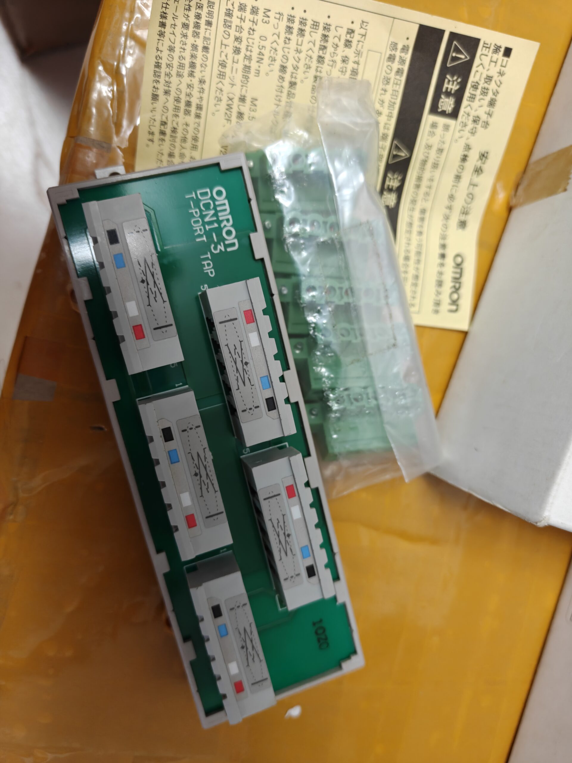

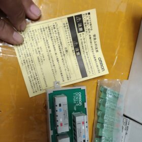
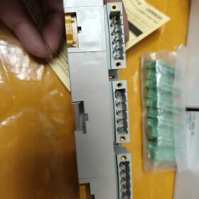
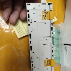
DCN13 è il nome di mercato comune; le designazioni ufficiali complete del modello sono DCN13C / DCN13NC. Si tratta di una derivazione Tbranch dedicata al bus di campo DeviceNet Thickcable, usato per dividere 3 nodi della discesa dalla linea dorsale. Viene fornito con un resistore di terminazione integrato da 120Ω e appartiene a Accessori periferici OMRON DeviceNet.
Scomposizione del codice modello
| Modello | Definizione del suffisso | Direzione del percorso dei cavi | Connettore di accoppiamento |
| DCN1‑3C | C = Uscita laterale | Il cavo esce orizzontalmente | XW4B‑05C1‑H1‑D (5 pz) |
| DCN1‑3NC | NC = uscita superiore | Il cavo esce verso l'alto | XW4G‑05C1‑H1‑D (5 pz) |
DCN1:Tocca DeviceNet TBranch
3:Massimo 3 uscite del ramo
C / NC:Direzione fisica dell'uscita del cavo; differenza solo meccanica, elettricamente identici.
Specifiche hardware principali
| Articolo | Specifiche |
| Protocollo autobus | DeviceNet (Basato su CAN), ramificazione del tronco del cavo spesso |
| Quantità di rami | 3 interfacce di filiale, 1-In / 1- passaggio del bagagliaio in uscita |
| Resistenza di terminazione incorporata | 120 OH (ON/OFF configurabile; i terminatori devono essere montati su entrambe le estremità fisiche del trunk) |
| 5‑Disposizione dei pin | 1: V‑; 2: CAN_L; 3: Scudo DRENAGGIO; 4: CAN_H; 5: V+ |
| Tipo di connettore | Connettore parallelo con morsetto a vite, per cavo spesso DeviceNet |
| Coppia di serraggio | 0.25‑0,3 N·m, cacciavite dedicato XW4Z‑00C |
| Certificazioni | UL, CE |
| Temperatura operativa | 0-60°C; Magazzinaggio:‑25‑85°C, vietata la formazione di condensa |
| Montaggio | Fori di montaggio M3; Montaggio su guida DIN non supportato, montaggio con viti a pannello solo sulla piastra posteriore dell'armadio |
Logica di cablaggio
- Collegare il bus trunk a monte alla porta IN di DCN13; collegare la porta OUT per continuare il trunk downstream.
- Collega le discese del dispositivo slave DeviceNet al 3 porti di filiale.
- 120 Le resistenze terminali da Ω devono essere montate solo alle due estremità fisiche dell'intero bus principale. Il resistore integrato di questa presa deve essere ABILITATO solo quando questa presa si trova all'estremità del bus fisico. Per tutti i nodi intermedi, il terminatore integrato DEVE essere disabilitato. In caso contrario si verifica una resistenza di rete anomala (intervallo normale di resistenza della rete: 5070 OH).
⚠️Sintomi di guasto: Errori di rete, schiavi non rilevati. Dai priorità alla risoluzione dei problemi: terminatori duplicati, messa a terra dello schermo, Inversione di polarità CAN_H/CAN_L.
Elenco completo delle serie
| Modello | Conteggio dei rami | Direzione di uscita |
| DCN1‑1C / DCN1‑1NC | 1 ramo | Lato / Superiore |
| DCN1‑2C / DCN1‑2R | 2 rami | Lato / Angolo retto |
| DCN1‑3C / DCN1‑3NC | 3 rami | Lato / Superiore |
| DCN1‑4C / DCN1‑4R | 4 rami | Lato / Angolo retto |
| DCN1‑1P | Rubinetto di alimentazione (con fusibile) | ‑ |
Finedellavita & Informazioni sulla sostituzione
- DCN13C / 3Le NC sono EOL (Finedellavita). L'ecosistema DeviceNet viene gradualmente eliminato; OMRON non fornisce alcun modello sostitutivo diretto di Pintopin.
- Opzioni di migrazione consigliate da OMRON:
OpzioneA: Impilare più DCN11C (1ramo) tocchi per realizzare la topologia multiramo.
OpzioneB: Connettore a T sigillato DCN311 (per sistemi sottili M12).
- Alternative compatibili con terze parti: Sono disponibili repliche aftermarket di DCN13C. Verificare la dimensione del connettore di accoppiamento (XW4B05C1H1D), terminatore commutabile da 120Ω e compatibilità con cavi spessi prima dell'acquisto.
Scenari applicativi tipici
Linee di saldatura per autoveicoli, linee di smistamento per la movimentazione dei materiali, macchine per stampaggio ad iniezione. Master DeviceNet PLC OMRON serie CS/CJ (C200HWDRM21V1 / CJ1WDRM21) collegamento in rete con moduli I/O remoti della serie DRT; distribuzione del nodo slave multiramo su un tronco di cavo spesso.
Linee guida per evitare le trappole della selezione
- ❗Distinguere la serie con cavo spesso DCN1 e la serie con cavo sottile DCN3: i connettori sono fisicamente incompatibili; non mescolare.
- ❗Non abilitare mai il terminatore integrato per i nodi bus intermedi; abilitare solo i terminatori alle due estremità del trunk fisico.
- ❗Utilizzare solo cavo schermato a 5 conduttori specifico per DeviceNet. Il cavo CANbus generico ha un'impedenza non corrispondente e causa la perdita del pacchetto di comunicazione.
- ❗Rispettare la coppia di serraggio rigorosa di 0,250,3 N·m. Una coppia eccessiva danneggia i conduttori del cavo; una coppia insufficiente causa una comunicazione instabile.
Appendice1: Serie DCN1 (Cavo spesso) Tabella di selezione del tocco del ramo DeviceNet
| Modello | Conteggio dei rami | Direzione di uscita | Terminatore commutabile da 120Ω | Montaggio su guida DIN | Utilizzo tipico |
| DCN1‑1C | 1-modo | Lato | SÌ | ❌ Solo montaggio a vite | Diramazione a punto singolo per nodo bus intermedio |
| DCN1‑1NC | 1-modo | Superiore | SÌ | ❌ Solo montaggio a vite | Cablaggio con uscita dall'alto per uno spazio compatto nell'armadio |
| DCN1‑2C | 2-modo | Lato | SÌ | ❌ Solo montaggio a vite | Ramificazione del sito vicino per 2 schiavi |
| DCN1‑2R | 2-modo | 90° Angolo retto | SÌ | ❌ Solo montaggio a vite | Instradamento ad angolo retto lungo le pareti laterali dell'armadio |
| DCN1‑3C | 3-modo | Lato | SÌ | ❌ Solo montaggio a vite | Nome comune DCN1‑3; ramificazione centralizzata per 3 nodi |
| DCN1‑3NC | 3-modo | Superiore | SÌ | ❌ Solo montaggio a vite | 3‑applicazione a nodo con passaggio cavi verso l'alto |
| DCN1‑4C | 4-modo | Lato | SÌ | ❌ Solo montaggio a vite | Breakout centralizzato per 4 dispositivi schiavi |
| DCN1‑4R | 4-modo | 90° Angolo retto | SÌ | ❌ Solo montaggio a vite | Cablaggio ad angolo retto ad alta densità |
| DCN1‑1P | 1Presa di alimentazione a due vie | Lato | NO | ❌ Solo montaggio a vite | Presa di alimentazione bus con fusibile integrato |
Nota importante: DCN1 = sistema a cavo spesso; DCN3 = sistema di cavi sottili M12. Incompatibilità fisica della spina; non possono essere mescolati all'interno di un tronco.
Appendice2: Elenco di controllo per la risoluzione dei problemi DCN13
Riferimento di impedenza di rete: Con i terminatori abilitati su entrambe le estremità del trunk e tutti i terminatori intermedi disabilitati, l'impedenza del bus sarà pari a 5070 Ω. Più terminatori abilitati riducono l'impedenza a ~30Ω e attivano errori di comunicazione.
📋 Verifica del cablaggio hardware
- Verificare l'assegnazione a 5 pin (fare riferimento allo schema dei pin):
Perno1: Alimentazione negativa del V Bus
Perno2: CAN_L
Perno3: SCUDO Scarico
Perno4: CAN_H
Perno5: V+ Alimentazione bus 24V
✅ Vietato: CAN_H / Inversione CAN_L; V+ / Inversione di polarità V: distruggerà l'hardware slave.
- Coppia della vite del terminale: 0.250.3 N·m. La coppia eccessiva rompe i conduttori; la sottocoppia crea una perdita di pacchetti intermittente correlata al contatto.
- Gestione dello scudo: Collegare il drenaggio dello schermo Pin3 a terra in un solo punto. Più punti di messa a terra creano interferenze del circuito di terra e frequenti errori di comunicazione.
📋 Risoluzione dei problemi relativi alla resistenza di terminazione (Fonte di errore con la massima probabilità)
- Interruttore a levetta Tapmount: Abilitare il terminatore interno da 120 Ω SOLO se questa presa si trova all'estremità fisica assoluta del trunk DeviceNet. Disabilita per tutti i nodi intermedi.
- L'intero trunk dovrà avere esattamente due terminatori, montato alle due estremità fisiche del tronco.
- Misurazione multimetro tra CAN_H / CAN_L:
Terminatore inserito su entrambe le estremità, tutti i terminatori intermedi spenti: 5070 Ω ✔OK
Terminatori multipli abilitati: <40Ω ❌ Guasto
Entrambi i terminatori finali sono spenti: Resistenza infinita ❌ Terminazione mancante
📋 Fenomeni di colpa, Cause principali & Rimedi
| Fenomeno di guasto | Probabile causa principale | Azione correttiva |
| Il PLC non riesce a rilevare tutti gli slave | Terminatori duplicati; CAN_H/CAN_L invertito; perdita dell'alimentazione 24V del bus | Controllare gli interruttori di terminazione; convalidare la piedinatura; misurare V+/V‑ (21-24 VCC) |
| Abbandono intermittente casuale di schiavi parziali | Crimpatura/coppia scarsa; messa a terra schermata multipunto; disadattamento di impedenza del cavo; instradamento adiacente ai cavi di alimentazione | E i terminali; messa a terra dello schermo a punto singolo; utilizzare un cavo DeviceNet originale; separati dai percorsi dei cavi di alimentazione |
| Hardware slave danneggiato immediatamente dopo l'accensione | Autobus V+ / Polarità V invertita | Spegnimento, convalidare il pin1 / polarità del pin5; sostituire gli schiavi danneggiati |
| Scansione di rete OK, frequenti errori nei dati I/O | La lunghezza della discesa supera le specifiche; topologie miste di cavi spessi/sottili | Lunghezza massima della linea di discesa per dorsale per cavi spessi: 6m. Non collegare l'hardware con cavo spesso DCN1 direttamente ai dispositivi con cavo sottile DCN3 M12. |
⚠️ Divieti HardConstraint
- ❌ È vietato il montaggio su guida DIN. Montaggio solo tramite viti M3 sulla piastra posteriore.
- ❌ Il cavo CANopen generico non può sostituire il cavo DeviceNet; disadattamento di impedenza.
- ❌ La lunghezza della singola discesa non deve superare i 6 m. Lunghezza massima del trunk rispetto alla velocità di trasmissione: 500 kbps=100m; 250 kbps=250m; 125 kbps=500m.
- ❌ Non attivare mai la terminazione interna della presa quando la presa è posizionata su un nodo armadiobus intermedio.
Appendice3: Raccomandazioni per l'aggiornamento EOL
DCN13C/DCN13NC sono EOL; OMRON non offre alcuna sostituzione immediata.
- Opzione di adeguamento1: Implementa più derivazioni DCN11C per il cablaggio distribuito mantenendo l'infrastruttura Thickcable originale (pezzi di ricambio ancora disponibili).
- Opzione di retrofit2: Migrazione dell'intero sistema alla topologia thincable DCN3series M12; tutti i connettori master/slave devono essere sostituiti, elevato sovraccarico di modifica hardware.
- Note sull'approvvigionamento di parti compatibili con terze parti: Conferma l'assegnazione del pin, terminatore commutabile da 120Ω, compatibilità con il calibro del conduttore per cavi spessi DeviceNet.
OMRON DCN13 (DCN13C / DCN13NC) Scenari applicativi
DCN13 è una presa T-branch DeviceNet con cavo spesso 3 uscite del ramo. Valore fondamentale: derivare tre discese da una singola posizione sul tronco del cavo spesso per l'I/O remoto, sensori, unità e altri dispositivi slave. Ottimizzato per il breakout multinodo centralizzato all'interno delle macchine / armadi di controllo. Rigorosamente per sistemi di cavi spessi; incompatibile con l'hardware thincable DCN3 M12.
Casi tipici di utilizzo nel settore
- Linee di produzione per saldatura automobilistica (Distribuzione più comune)
Architettura di rete: OMRON CJ1WDRM21 / PLC serie CS come master DeviceNet; tronco di grosso cavo instradato lungo le stazioni di saldatura.
Utilizzo DCN13: Una stazione ospita tre I/O remoti della serie DRT, isole di valvole o controllori di saldatura. Un DCN13 fornisce tre discese locali, eliminando più Ttap collegati in cascata e riducendo il numero totale di connettori bus e i punti di guasto della comunicazione.
Vincoli: Ogni singola discesa ≤6m. Rubinetto fissato alla piastra posteriore dell'armadio della stazione con viti M3.
- Movimentazione dei materiali & Sistemi di trasporto
Attrezzatura: Trasportatori a rulli, meccanismi di trasferimento di ordinamento, cilindri di bloccaggio, rilevatori fotoelettrici.
Applicazione: Una dorsale passa accanto ad una navetta di smistamento / unità di trasferimento con tre nodi I/O remoti simultanei. DCN13 implementa la ramificazione centralizzata per DR2 / Moduli I/O slave DRT DeviceNet.
Vantaggio: Riduce l'ingombro dei cavi all'interno dell'armadio rispetto a più prese DCN11 a ramo singolo.
- Stampaggio ad iniezione & Macchine per estrusione
Rete: Il bus DeviceNet all'interno della macchina per lo stampaggio collega i moduli di ingresso della temperatura, azionamenti per valvole proporzionali e moduli di ingresso di sicurezza.
Posizionamento: Instradamento interno del quadro elettrico; ramificazione locale per tre dispositivi slave co-localizzati.
Nota: Ambiente con elevato rumore elettrico all'interno delle macchine a iniezione. Il drenaggio dello schermo deve essere messo a terra in un unico punto; vietata la messa a terra multipunto.
- Macchine per l'imballaggio (Cibo & Imballaggio farmaceutico)
Macchine: Incartonatrici, pallettizzatori, macchine sigillatrici.
Scenario: Tre set di slave DeviceNet (isole valvole, I/O di rilevamento) raggruppati su un lato del mobile; DCN13 per il breakout concentrato della discesa.
Limiti ambientali: Temperatura di esercizio 060°C. Non adatto ad ambienti con forte condensa o atmosfera corrosiva.
- Macchine utensili & Macchine di automazione per scopi speciali costruite su misura
Postazioni di lavoro per attrezzature e attrezzature: Tre nodi slave di acquisizione del segnale in una stazione di lavoro dove passa il tronco del cavo spesso. DCN13 per la ramificazione locale.
Nota: Evitare l'esposizione diretta al fluido da taglio della macchina utensile; installare all'interno della custodia protettiva.
A livello di gabinetto / Scenari di topologia montata su macchina
- Derivazione centralizzata all'interno del quadro elettrico
Il cavo spesso DeviceNet passa attraverso l'armadio. Tre moduli slave risiedono all'interno dell'armadio. DCN13 fissato alla piastra posteriore dell'armadio: IN per il trunk a monte, OUT continua a valle del tronco; tre porte di diramazione si collegano a tre dispositivi slave.
Quando DCN13 non si trova all'estremità della linea fisica: il terminatore interno da 120Ω deve essere spento.
- Montato all'interno della scatola di giunzione sul campo
Il cavo principale entra in una scatola di giunzione classificata; tre discese si dirigono verso le isole valvole di campo / Moduli I/O. Tap stesso non ha IPrating; deve essere completamente racchiuso all'interno di una scatola di giunzione protettiva, mai esposto all'aperto.
Scenari non applicabili (Avvertenze sulla selezione)
- ❌ Cavo sottile DeviceNet (M12) sistemi: DCN13 è disponibile solo con cavo spesso, hardware incompatibile con la serie DCN3; non mescolare.
- ❌ Richiede solo la posizione Trunkend 12 nodi: Preferisco DCN11C / DCN12C, evitare di specificare eccessivamente DCN13.
- ❌ Lunghezza discesa individuale>6m: DeviceNet thickcable dropline hardlimit; excess length destabilizes network.
- ❌ Outdoor installation, direct fluid spray, heavy condensation, corrosive atmosphere.
- ❌ Direct DINrail mounting: No DINclip hardware; only M3 panelscrew mounting allowed.
- ❌ CANopen bus usage: Similar physical connector, protocollayer incompatible; cannot operate on CANopen networks.
Reference BillofMaterial for Matching Hardware
PLC Master Units: CJ1WDRM21, C200HWDRM21V1
Slave I/O: DRT2ID, DRT2OD, DRT2MDseries remote I/O
Valve Islands: SMC DeviceNet valveisland, Festo DeviceNet valveisland
Cavo: DeviceNetspecific 5core shielded thickcable
OMRON DCN13 (DCN13C / DCN13NC) Istruzioni per l'installazione
⚠️ Critico: DCN13 has no DINrail clip. Direct DINrail mounting is unsupported. Panelscrew mounting only.
- Specifiche di installazione meccanica
| Articolo | Valore |
| Stile di montaggio | Panel‑mount to cabinet backplate / mounting panel |
| Fori di montaggio | 2 × Φ3.5 mm through‑holes for M3 screws |
| Recommended Fasteners | M3 pan‑head screws |
| Device‑body tightening torque | 0.4‑0,5 N·m. Non serrare eccessivamente per evitare rotture dell'alloggiamento. |
| Dimensione complessiva (DCN1‑3C) | 142(l) × 45(W) × 31.3(D) mm |
| Orientamento di montaggio | Arbitrario (orizzontale / verticale). Lasciare spazio sufficiente per maneggiare i cavi e accedere ai cacciaviti. |
Differenza di routing meccanico: DCN13C rispetto a DCN13NC
- DCN13C (C=Uscita laterale)
I cavi escono orizzontalmente dal lato dell'unità. Adatto per il montaggio in piano sulla piastra posteriore dell'armadio con passaggio cavi orizzontale.
- DCN13NC (NC=Uscita superiore)
I cavi escono verticalmente verso l'alto dalla parte superiore dell'unità. Utilizzato quando il luogo di installazione ha uno spazio inferiore limitato.
Le prestazioni elettriche sono identiche; la selezione dipende esclusivamente dalla geometria del cablaggio sul campo.
- Procedura di installazione standard
- Praticare due fori di montaggio da Φ3,5 mm sulla piastra posteriore dell'armadio secondo il disegno dimensionale.
- Fissare il corpo DCN13 alla piastra posteriore dell'armadio con viti M3; coppia 0,40,5 N·m.
- Lasciare spazio tutto intorno per l'accesso al connettore e l'utilizzo del cacciavite.
- Terminare i cavi spessi DeviceNet:
IN: Autobus di linea a monte; FUORI: Continuare a valle dell'autobus principale.
Le restanti tre porte collegano le discese ai rispettivi dispositivi slave.
Coppia della vite del terminale del connettore=0,250,3 N·m. La coppia eccessiva danneggia i trefoli del cavo; la sottocoppia provoca errori di comunicazione intermittenti.
- Configurare l'interruttore a levetta del terminatore da 120 Ω integrato:
Tocca situato sul nodo bus intermedio → TerminatorOFF.
Toccare situato all'estremità fisica assoluta del trunkbus → TerminatorON.
- Cablaggio della schermatura: Perno3 (SCHERMO/SCARICO) collegato alla terra protettiva solo in un unico punto di terra. È vietata la messa a terra su più punti per evitare disturbi dovuti al ritorno di terra.
- Requisiti relativi alla posizione di installazione
- ✅ Ambienti accettabili: Piastra posteriore interna del quadro elettrico; all'interno della scatola di giunzione protettiva; temperatura ambiente060°C, senza condensa.
- ❌ Condizioni di installazione vietate:
Montaggio diretto su guida DIN (la reggiatura con cavi porta ad allentamenti indotti dalle vibrazioni e a guasti intermittenti).
Montaggio esterno a vista, spray fluido da taglio diretto.
Montaggio nelle immediate vicinanze dei VFD, contattori e componenti ad alta potenza; mantenere l'autorizzazione per la mitigazione del rumore.
Compartimenti confinati sigillati che comportano un aumento della temperatura superiore a 60°C.
- Vincoli topologici rigidi di cablaggio (Da seguire per l'installazione dell'hardware)
- Lunghezza massima della singola discesa: 6 m limite assoluto per il sistema a cavi spessi. Discese più lunghe compromettono la stabilità della rete.
- Lunghezza massima della dorsale rispetto alla velocità di trasmissione:
500 kbps: 100 metri massimo
250 kbps: 250 metri massimo
125 kbps: 500 metri massimo
- Alle due estremità fisiche del trunkbus devono essere abilitati esattamente due terminatori da 120Ω. Tutti i terminatori di presa del nodo intermedio rimarranno disabilitati.
- Errori comuni di installazione & Insidie
- ❌ Fissaggio dell'unità alla guida DIN solo con fascette: Le vibrazioni allentano il montaggio, attiva interruzioni casuali della rete.
- ❌ Coppia eccessiva della vite del terminale: Lo schiacciamento del conduttore crea guasti latenti e intermittenti.
- ❌ Messa a terra schermata multipunto: Errori di comunicazione ad alta frequenza e perdita di pacchetti.
- ❌ Abilitazione accidentale del terminatore integrato quando il rubinetto si trova sul nodo cabinetbus intermedio: Bassa impedenza di rete.
- ❌ Lunghezza della discesa superiore a 6 m.
- Installazione di scenari speciali
Montaggio su scatola di giunzione: Proteggi DCN13 all'interno della scatola di giunzione con grado di protezione IP. Il rubinetto stesso non ha alcuna classificazione di protezione ambientale e non deve mai essere esposto.
Armadi dalle dimensioni compatte: Preferire il modello con uscita superiore DCN13NC per ridurre l'interferenza del cavo orizzontale.





NH42-63-318x560.png "Commutatori automatici di tipo PC CHINT (ATS)NH42-63/4SZ")



