 Contattore,interruttore automatico,sensore,Codificatore,PLC,Convertitore

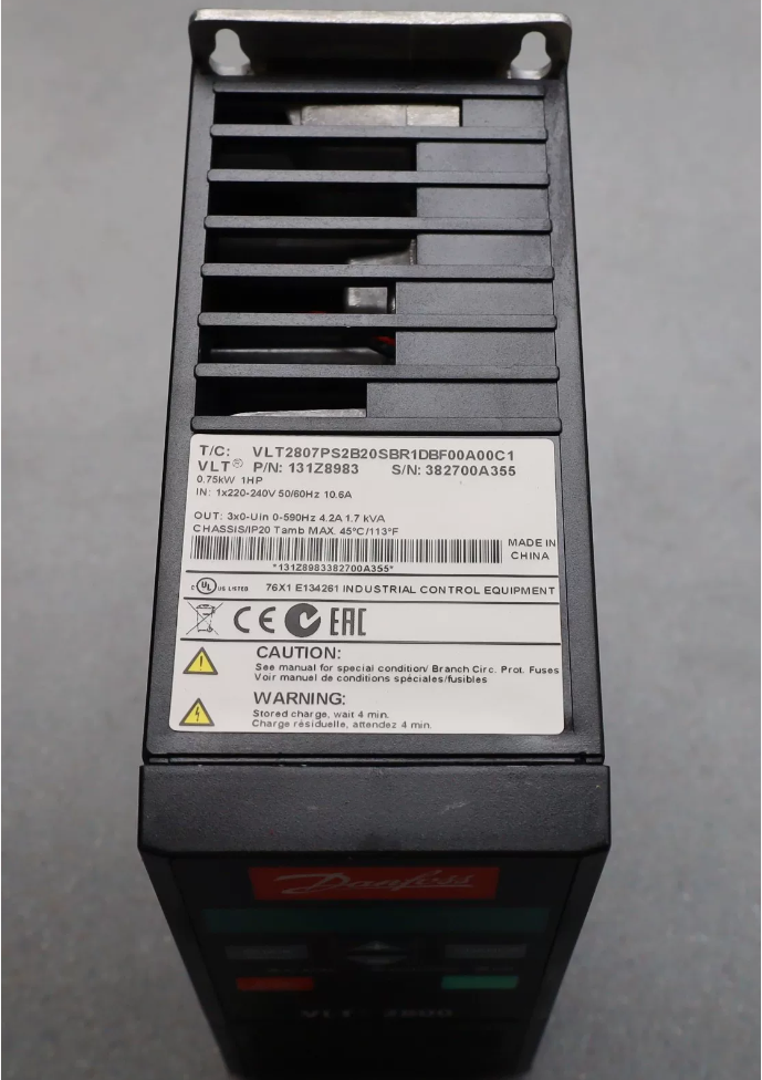

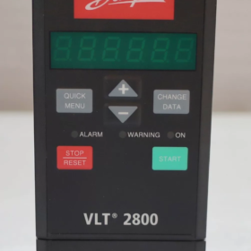
Scenari applicativi tipici per Danfoss VLT2807 (0.75 kW)
Il VLT2807 è un convertitore di frequenza V/F ad anello aperto di piccole dimensioni per uso generale. Supporta la coppia costante (CT) / Coppia variabile (VT) selezione, Autoadattamento PID e AMA integrati. È supportata l'installazione affiancata compatta. Utilizzato principalmente per apparecchiature OEM, Azionamenti HVAC per l'industria leggera e le catene di montaggio. Non adatto per il controllo vettoriale ad alta precisione, carichi ad urto pesante o applicazioni di sollevamento ad alta inerzia.
Stato: Interrotto. Legacy compatto per uso generale convertitore di frequenza, 0.75 kW, ampiamente utilizzato per i fan, pompe, linee di assemblaggio e apparecchiature di azionamento di piccole dimensioni.
- Decodifica del modello (Esempio di modello completo: VLT2807PT4B20SBR1DBF12A00C1)
28: Serie VLT2800
07: Potenza nominale 0,75 kW / 1HP
P: Variante di processo
T: Ingresso trifase
4: 380-480 V.AC
B: Costruzione in stile libro, IP20
R1: Filtro EMC classe A1 integrato; R0 = Nessun filtro EMC
D: Nessun chopper di frenatura; B = Chopper di frenatura integrato
F12: Pannello di controllo locale LCP; F00 = Senza pannello
Numero d'ordine di esempio: 134H2368 (con filtro EMC e pannello di controllo)
- Specifiche elettriche principali (380-480 Versione V)
| Articolo | Specifica |
| Potenza nominale | 0.75 kW (1HP) |
| Alimentazione elettrica | 3×380‑480 V ±10%, 50/60 Hz |
| Corrente di uscita nominale | 4.2 UN |
| Potenza apparente | 1.7 kVA |
| Classe di protezione | IP20 |
| Frequenza di commutazione | 4‑16kHz regolabile |
| Dissipazione del calore | Montaggio su armadio; mantenere uno spazio libero di 100 mm sopra e sotto |
| Peso netto | ca. 2.1 kg |
Una versione monofase 220V VLT2807 (1×220-240 V) è anche disponibile, stessa potenza nominale di 0,75 kW, 4.2 Una corrente di uscita.
- Panoramica dell'interfaccia hardware
Terminali del circuito principale
Ingresso: L1, L2, L3; Uscita del motore: U, V, W; Terra di protezione PE; Terminali della resistenza di frenatura (solo varianti selezionate)
Terminali di controllo (Serie VLT2800)
Ingressi digitali: 18, 19, 27, 29, 33
Ingressi analogici: 53 (tensione/corrente), 60 (attuale)
Uscita analogica: 42
RS485: 68/69 (Profibus-DP tramite scheda di espansione opzionale)
Funzioni supportate: Multivelocità, avviare/interrompere, PID, riferimento analogico, riferimento agli impulsi, arresto di precisione, riavvio automatico, Frenatura CA.
- Caratteristiche principali
- Menù rapido: Messa in servizio rapida con 12 parametri chiave di configurazione del motore; supporta l'adattamento automatico del motore AMA (Parametro P107).
- Controllo V/F; coppia costante selezionabile / modalità a coppia variabile; PID integrato per applicazioni di alimentazione idrica e ventilazione a pressione costante.
- Supporta resistenza freno e frenatura CA; ripristino automatico e riavvio automatico dei guasti.
- Schede di espansione bus di campo Profibus-DP e DeviceNet opzionali.
- Il pannello LCP supporta la copia dei parametri per la messa in servizio dell'unità batch.
- Soluzione sostitutiva del prodotto fuori produzione
Sostituzione diretta ufficiale: VLT Midi Drive FC280, 0.75 kW, 380-480 V
Dimensioni di montaggio e disposizione dei terminali altamente compatibili; i terminali plug-in sono riutilizzabili; i parametri possono essere migrati.
Aggiunto Safe Torque-Off (STO) funzione di sicurezza con prestazioni complessive migliorate.
Riferimento alternativo: FC-051 (tipo economico, non compatibile direttamente con il terminale; richiede un ricablaggio completo per il retrofit).
- Codici di errore comuni
Err8: Sottotensione del bus CC. Controllare la tensione in ingresso, caduta di tensione di alimentazione o perdita momentanea di potenza.
Err1: Sovracorrente; Err4: Guasto di terra; Err14: Guasto a terra; Err16: Cortocircuito; Err29: Sovratemperatura.
- Lista di controllo per l'ispezione delle unità di seconda mano
- Controllo visivo: Condensatori elettrolitici gonfi, Corrosione del PCB, invecchiamento del ventilatore.
- Accensione senza motore: Controlla gli allarmi; testare tutti i tasti del pannello.
- Funziona con motore di piccole dimensioni a vuoto; verificare il bilanciamento della tensione di uscita trifase.
- Verificare la potenza nominale, presenza di filtro EMC e chopper di frenatura integrati.
- Backup del set di parametri completo. I condensatori elettrolitici rappresentano il principale rischio di guasto su questa serie legacy.
- Carichi a coppia variabile (Tifosi & Pompe, Modalità TV)
La coppia diminuisce con la velocità; funzionamento a risparmio energetico; PID integrato per la regolazione della pressione/flusso a circuito chiuso.
- Piccoli ventilatori centrifughi: Aspiratori da officina, ventole di raffreddamento dell'armadio, ventilatori delle unità di trattamento dell'aria, piccoli ventilatori per il trattamento dei gas di scarico.
- Approvvigionamento idrico / pompe di circolazione: Approvvigionamento idrico a pressione costante su piccola scala, pompe di circolazione dell'acqua di raffreddamento, pompe dosatrici, pompe di reintegro di processo.
- Unità terminali HVAC e sistemi di ventilazione di piccoli edifici.
✅Vantaggi: Funzione sonno-risveglio PID; avvio graduale per ridurre al minimo il colpo d'ariete; notevole effetto di risparmio energetico.
- Carichi a coppia costante (Modalità CT, 160 % di sovraccarico per 1 minuto)
La coppia rimane in gran parte indipendente dalla velocità; richiesta una coppia di avviamento sufficiente. Principalmente per catene di montaggio e macchinari dell'industria leggera.
- Attrezzature di trasporto: Piccoli nastri trasportatori, trasportatori a rulli, trasportatori a catena, attrezzature per linee di smistamento.
- Macchine per l'imballaggio: Piccole macchine confezionatrici, sigillanti, etichettatrici; funzione di arresto di precisione per il posizionamento della stazione.
- Attrezzature per miscelazione-agitazione: Piccoli serbatoi di miscelazione, frullatori e agitatori.
- Industria leggera & tessile: Azionamenti ausiliari per svolgitura/avvolgimento di piccole dimensioni, macchine tessili e attrezzature per il taglio.
- Estrusione & apparecchiature per piccoli processi: Microestrusori, alimentatori di materiale.
Nota: Per un funzionamento prolungato al di sotto di 10 Hz, il raffreddamento del motore standard si deteriora. Si consiglia un motore a frequenza variabile con ventola di raffreddamento separata.
III. Settori industriali
- HVAC: Ventilatori e pompe di circolazione (applicazione più comune).
- Confezione & OEM dell'industria leggera: Unità di azionamento di piccola potenza integrate nei macchinari.
- Trattamento dell'acqua: Pompe dosatrici di piccole dimensioni per l'approvvigionamento idrico e il dosaggio di prodotti chimici.
- Cibo & bevanda: Piccoli trasportatori e agitatori.
- Automazione generale di fabbrica: Azionamenti ausiliari per linee di produzione.
- Condizioni operative non idonee
- Sollevamento ad alta inerzia / macchine di sollevamento (consentito solo per meccanismi ausiliari leggeri, non per azionamenti di sollevamento principali).
- Applicazioni che richiedono controllo vettoriale a circuito chiuso o prestazioni di livello servo con risposta dinamica elevata.
- Funzionamento gravoso continuo con frequenti carichi d'urto.
- Funzionamento del mandrino ad alta velocità a lungo termine superiore a 400 Hz.
- Suggerimenti di configurazione per applicazioni tipiche
- Fan / pompa: Selezionare la variante R1 con filtro EMC integrato; impostare P101 su Coppia variabile (VT).
- Trasportatore / agitatore: Richiede un'elevata coppia di avviamento; impostare P101 su Coppia costante (CT). Per frequenti frenate, selezionare la variante con chopper di frenatura integrato (suffisso B nel codice modello).
- Controllo del bus di campo: Aggiungere la scheda opzionale Profibus-DP per l'interfacciamento con il PLC.
Specifiche tecniche complete di Danfoss VLT2807 (Serie VLT2800)
Stato: Interrotto. 0.75 kW, disponibile nelle versioni monofase 220V e trifase 380-480V.
- Parametri elettrici dello stadio di potenza
① Trifase 3×380-480V (VLT2807PT4 ampiamente utilizzato)
| Articolo | Specifica |
| Potenza nominale del motore | 0.75 kW / 1HP |
| Corrente di uscita nominale continuativa Iinv | 2.1 UN |
| 60‑seconda corrente di sovraccarico | 3.3 UN (160 % di sovraccarico per 1 minuto) |
| Potenza apparente | 1.7 kVA |
| Alimentazione in ingresso | 3×380‑480 VCA ±10%, 50/60 Hz |
| Corrente di ingresso nominale | 1.9 UN |
| 60‑s corrente di ingresso massima | 3.0 UN |
| Intervallo di tensione del bus CC | 540-800 VCC |
② Monofase 1×220-240V (VLT2807P1)
| Articolo | Specifica |
| Potenza nominale del motore | 0.75 kW / 1HP |
| Corrente di uscita nominale continuativa Iinv | 4.2 UN |
| 60‑seconda corrente di sovraccarico | 6.7 UN (160 % di sovraccarico per 1 minuto) |
| Potenza apparente | 1.7 kVA |
| Alimentazione in ingresso | 1×220‑240 VCA ±10%, 50/60 Hz |
| Corrente di ingresso nominale | 10.6 UN |
| 60‑s corrente di ingresso massima | 16.7 UN |
| Intervallo di tensione del bus CC | 280-380 VCC |
Valutazione di sovraccarico: Coppia costante (CT): 160 %, 60 S; Coppia variabile (VT): 110 % continua.
- Parametri di prestazione
Principio di controllo: Controllo V/F ad anello aperto. Curva V/F programmabile dall'utente; nessuna capacità vettoriale a circuito chiuso.
Gamma di frequenza di uscita: 0-1000 Hz; impostazione predefinita di fabbrica 0-50 Hz.
Frequenza di commutazione della portante: 4-16 kHz regolabile, impostazione predefinita di fabbrica4kHz. Il declassamento della corrente si applica a frequenze di commutazione più elevate.
Autoadattamento motore AMA: AMA statico supportato (P107).
Accelerazione / tempi di decelerazione: 0.05-3600 S; quattro set di tempi di rampa indipendenti selezionabili.
Controller PID integrato: Circuito chiuso per ventilatori/pompe; sonno-veglia, protezione contro il funzionamento a secco, rilevamento della mancanza di flusso.
Modalità di frenata: Frenatura AC; chopper di frenatura integrato opzionale (-Suffisso del modello B) per resistenza freno esterna; Parallelamento del bus DC per la condivisione del carico.
Funzioni di riavvio: Reset automatico dei guasti & ricomincia, partenza al volo, protezione da caduta di potenza.
III. Valutazioni dei terminali di controllo
Ingressi digitali (DI: Terminali18,19,27,29,33)
Quantità: 5 ingressi digitali; alimentazione interna a 24 V; compatibile con NPN / Logica PNP.
Funzioni: Inizio-stop, avanti/indietro, multivelocità, ripristino degli errori, riferimento agli impulsi, inibizione dell'uscita.
Ingressi analogici
- Terminale53: 0-10 tensione V / 0-20 mA / 4-20 mA, configurabile.
- Terminale60: 4-20 Solo ingresso di corrente mA.
Uscita analogica (Terminale42)
1 uscita analogica: 0-20 mA / 4-20 mA programmabile. Può produrre la frequenza, corrente di uscita, tensione di uscita e altre variabili di processo.
Uscita relè
1 uscita relè; portata dei contatti AC250V / 3 UN. Configurabile per segnale di guasto, guidare in corsa, frequenza raggiunta e altri segnali di stato.
Interfacce di comunicazione
- Standard: RS485 (Terminali68/69), supporta i protocolli Modbus-RTU e Metasys-N2.
- Schede di espansione opzionali: Profibus-DP, DeviceNet (opzione hardware richiesta).
- Meccanico & Specifiche ambientali
| Articolo | Specifica |
| Tipo di custodia | Stile libro, IP20; solo montaggio su armadio |
| Dimensioni (A×L×P) | 200 ×75×168 mm |
| Peso netto | ca. 2.1 kg (senza pannello); 2.2‑2,6kg con pannello+filtro |
| Montaggio | Montaggio a parete verticale; è consentito il montaggio stretto affiancato; Spazio verticale superiore/inferiore ≥100 mm |
| Coppia dei terminali del circuito principale | 0.5‑0,6 Nm; Terminale di terra PE2‑3Nm |
| Temperatura ambiente operativa | 0-50°C; declassamento sopra i 45°C |
| Temperatura di conservazione | -20°C ~ +65°C |
| Altitudine | Nessun declassamento ≤1000 m sopra il livello del mare; declassamento richiesto >1000 M |
| Classe di protezione | IP20; non per installazione esterna |
- Lunghezza massima consentita del cavo motore
Cavo non schermato: 200 M (con motore-reattore montato).
Cavo schermato: 100 M (con motore-reattore montato).
Versione R1 (filtro A1-EMC integrato): Massimo. 50 cavo schermato da m.
Versione R0 (nessun filtro integrato): Massimo. 25 cavo schermato da m.
- EMC & Standard di sicurezza
Variante R1: Conforme alla norma EN55011 Classe A1 (filtro EMC industriale). R0: Nessun filtro interno.
Approvazioni: UL, CE. Nessun Safe-Torque-Off integrato (STO) (STO introdotto sul successore FC280).
VII. Ripartizione del codice modello (Stringa modello completo VLT2807)
VLT2807PT 4 B 20 S B R1 D B F12 A00 C1
P=Processo; T=Trifase; 4 =380-480V; B=Stile libro; 20 =IP20
R1=Filtro A1-EMC integrato; R0=Nessun filtro
D=Nessun chopper di frenatura; B=Chopper di frenatura integrato
F12=Con tastiera LCP; F00=Senza tastiera
VIII. Numeri d'ordine di riferimento
VLT2807PT4B20SBR1DBF12A00C1 (con filtro + pannello): 134H2368
VLT2807PT4B20STR0DBF00A00C1 (nessun filtro, nessun pannello): 195N1013
- Confronto dei parametri del modello sostitutivo
FC280 Midi Drive 0,75kW, 380-480 V
Potenza identica; elevata compatibilità terminale-hardware; Funzione di sicurezza STO integrata; RS485 standardModbus. Sostituzione hardware diretta per VLT2807.
Modalità di controllo di Danfoss VLT2807
Parametro P100 (Modalità di configurazione) definisce la modalità operativa dell'azionamento di alto livello. L'algoritmo del motore sottostante è fissato come V/F ad anello aperto. Il controllo vettoriale e il controllo orientato al campo non sono supportati.
- Algoritmo di controllo del motore sottostante
- V/F ad anello aperto (Tensione-frequenza) controllare (unico algoritmo di controllo motorio)
Coppia costante selezionabile (CT) / Coppia variabile (VT) via P101; curva V/F personalizzata disponibile.
L'adattamento automatico del motore AMA statico è supportato per la compensazione della caduta di tensione motore-statore.
Nessun controllo vettoriale della velocità ad anello chiuso basato su encoder; non per la regolazione della velocità ad alta precisione.
- Quattro impostazioni della modalità operativa del parametro P100
| Valore P100 | Nome della modalità | Descrizione | Applicazione tipica |
| 0 | Controllo della velocità ad anello aperto | V/F ad anello aperto; riferimento di velocità da fonte esterna; nessun feedback | Tifosi, pompe, trasportatori, regolazione della velocità per scopi generali (l'impostazione più utilizzata) |
| 1 | Controllo della velocità a circuito chiuso | L'interfaccia dell'encoder hardware non è disponibile sul VLT2807. Questa è un'opzione di menu residua e non può essere utilizzata in progetti pratici. | Controllo della velocità ad anello chiuso basato su encoder (non implementabile su VLT2807) |
| 2 | Prenotato | Impostazione di riserva | Non utilizzato |
| 3 | Controllo PID di processo ad anello chiuso | Controller PID integrato, regola in base al segnale di feedback del processo di pressione/portata | Alimentazione idrica a pressione costante, ventilatori a volume d'aria costante; disponibile la funzione di sospensione della pompa |
✅ Utilizzo pratico sul campo: P100=0 Controllo velocità ad anello aperto e P100=3 Controllo PID di processo ad anello chiuso.
III. Fonte di riferimento & Opzioni dell'origine del comando
- Controllo del pannello locale (Tastiera LCP)
Parametro 002=1 LOCALE
Inizio-stop, avanti/indietro e riferimento di frequenza impostati tramite i pulsanti della tastiera.
Utilizzato per la messa in servizio e il funzionamento manuale locale di unità autonome.
- Controllo remoto tramite terminale esterno (Parametro002=0 REMOTO)
① Impostazione della velocità di riferimento analogico
Terminale53: 0-10 V / 0-20 mA / 4-20 mA; impostazione della velocità tramite potenziometro.
Terminale60: 4-20 Solo ingresso di corrente mA.
Morsetto33 configurabile come riferimento di frequenza di impulsi, massimo 67,6 kHz.
② Controllo del terminale digitale
Multivelocità: Combinazioni di terminali di ingresso digitale, fino a 8 setpoint di velocità fissa preimpostati.
Start-stop e direzione: Terminal18 per l'inizio, Morsetto 19 per la retromarcia.
Funzione Jog, arresto di precisione, ripristino degli errori, inibizione dell'uscita.
- Controllo della comunicazione tramite bus di campo
- RS485 nativo (Terminali68/69): Modbus-RTU, Metasys-N2. Il PLC controlla l'avvio-arresto, riferimento di velocità e accesso ai parametri.
- Schede di espansione opzionali: Profibus-DP / DeviceNet per comando basato su bus & riferimento.
- Controllo con origine mista
La sorgente del comando e la sorgente del riferimento potrebbero differire. Esempio: Terminali per start-stop mentre il bus fornisce il riferimento di frequenza; oppure bus per start-stop con riferimento analogico a potenziometro.
- Modalità di frenata
- Frenatura AC: Eccitazione CA a bassa frequenza per una decelerazione rapida; nessun hardware aggiuntivo richiesto.
- Frenatura con iniezione DC: Iniezione DC per bloccare l'albero motore durante l'arresto; tempo di frenatura e livello di tensione di frenatura configurabili.
- Chopper di frenatura + resistenza freno (-Suffisso del modello B): Frenatura a dissipazione di energia per applicazioni con carico rigenerativo a inerzia elevata.
- Tipi logici start-stop
- Inizio-fine rampa: Accelerazione fluida / rampa di decelerazione seguendo tempi di accelerazione-decelerazione.
- Partenza in volo: Rileva e sincronizza la velocità del motore già in rotazione.
- Arresto di precisione: Battuta su bancone per il posizionamento della stazione di trasporto.
- Sosta a costa libera; Arresto rapido OFF3.
- Funzioni di controllo non supportate
❌ Nessun controllo vettoriale (ma VVC-plus, nessun vettore di flusso).
❌ Nessun controllo della velocità ad anello chiuso basato su encoder (nessuna interfaccia encoder hardware).
❌ Nessun posizionamento o servocontrollo della posizione.
❌ Nessun Safe-Torque-Off (STO).
Esempi tipici di configurazione dell'applicazione
- Tifoso generale / regolazione della velocità del trasportatore: P100=0 Velocità ad anello aperto; terminale-inizio-fine + riferimento del potenziometro sul Morsetto53.
- Pompa di alimentazione idrica a pressione costante: P100=3 PID di processo ad anello chiuso; 4-20 Trasmettitore di pressione mA collegato al Morsetto60.
- Controllo bus di campo PLC: P100=0 Velocità ad anello aperto; RS485 Modbus-RTU; start-stop e riferimento di velocità completamente tramite bus.





NH42-63-318x560.png "Commutatori automatici di tipo PC CHINT (ATS)NH42-63/4SZ")



