 Contattore,interruttore automatico,sensore,Codificatore,PLC,Convertitore

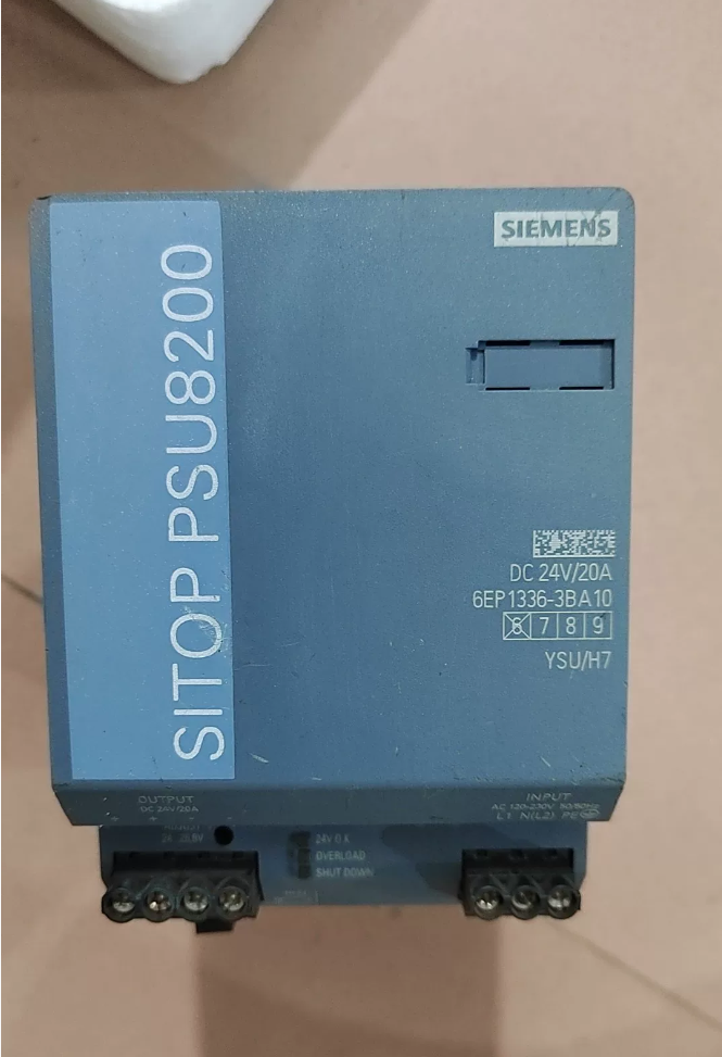

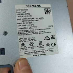
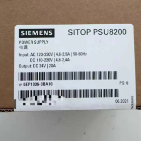
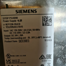
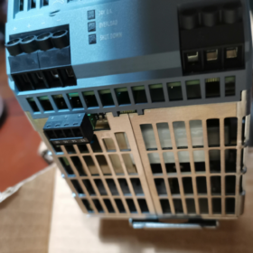
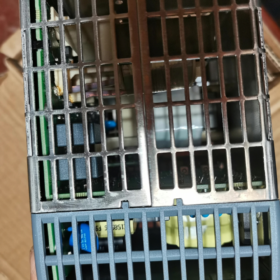
Ordine n.: 6EP1336-3BA10
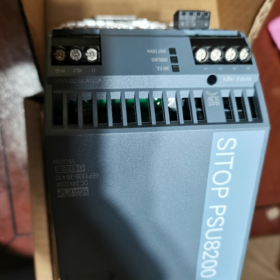
Designazione completa: SITOP PSU8200 /1ACDC /24VDC /20A Alimentatore switching industriale su guida DIN
Produzione: 24 VCC20A, 480 W; Supporta il funzionamento in parallelo per l'espansione della potenza e il funzionamento ridondante
- Specifiche elettriche principali
Ingresso (Esclusivo doppio ingresso AC/DC per questo modello)
Classe AC: 120-230 V.AC, intervallo operativo 85-275 V CA, 50-60 Hz
DC nominale: 110-220 VCC, intervallo operativo 88-350 V CC
Corrente in ingresso: 2.5 A @230VAC; 4.6 A @120VAC
Tempo di attesa: ≥20ms al carico nominale
⚠️ È necessario un declassamento della potenza quando la tensione di ingresso <100 V
Produzione
Nominale: 24 VCC / 20 UN
Gamma regolabile: 24.0-28.8 VCC (potenziometro sul pannello frontale per compensazione caduta di tensione su cavo lungo)
Funzione Power Boost: Fino a 3 volte la corrente nominale (60 UN) per carichi di spunto come l'avvio di motori e relè; modalità a corrente costante selezionabile o spegnimento ritardato in caso di cortocircuito
Uscita galvanicamente isolata; protezione contro il cortocircuito, sovraccarico, sovratensione e sovratemperatura; ripristino automatico dopo l'arresto per temperatura eccessiva
Efficienza: ca. 93%-94%
Terminali di segnale
- 24Contatto relè V-OK (13-14): Contatto pulito senza potenziale, chiuso quando l'alimentazione funziona normalmente, per la diagnosi dello stato del PLC
- Accensione/spegnimento remoto (15-16): Contatto pulito per attivazione remota esterna / disattivazione dell'uscita 24V
- Meccanico & Dati ambientali
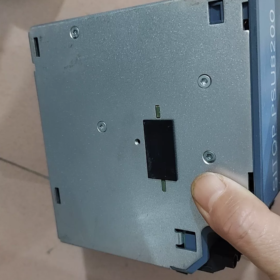
Montaggio: A scatto su guida DIN standard, alloggiamento in metallo, raffreddamento a convezione naturale senza ventola
Dimensioni: L90 mm × A 125 mm × P 125 mm
Peso: ca. 1.2 kg
Classe di protezione: IP20 (solo per l'uso con montaggio in armadio)
Temperatura operativa: -25℃~+70℃; declassamento sopra i 60 ℃; massimo. 75 Carico percentuale a 70 ℃
Spazio per la dissipazione del calore: Spazio libero superiore ≥50mm & metter il fondo a; le unità possono essere montate strettamente una accanto all'altra
Certificazioni: CE, UL/cUL, CCC, Omologazione marina GL, RoHS
III. Evoluzione del modello & Opzioni di sostituzione
- Sostituzione diretta del predecessore: 6EP1336-3BA00 (interrotto)
6EP1336-3BA10 è una versione rinnovata dall'hardware, pin-to-pin, dimensione per dimensione, sostituzione drop-in compatibile con le funzioni, con maggiore efficienza e prestazioni migliorate a bassa tensione di ingresso.
- Nuovo progetto serie SITOP PSU6200 di nuova generazione: 6EP3336-8SB00-0AY0
Nota: 6EP3336-8SB00-0AY0 supporta solo l'ingresso CA, nessuna capacità di ingresso CC. Non compatibile con l'hardware; le assegnazioni dei terminali differiscono, prestare attenzione durante la selezione.
- Moduli di estensione compatibili (Sistema modulare PSU8200)
Direttamente compatibile con gli add-on SITOP modular senza adattatori aggiuntivi:
Modulo tampone: 6EP1961-3BA21; Modulo di continuità DC-UPS
Modulo di ridondanza: 6EP1961-3BA00; per alimentazione ridondante a doppia alimentazione
Modulo selettivo: 6EP1961-3BA31, protezione di limitazione di corrente del ramo 24V multicanale; il cortocircuito su un ramo non farà collassare l'intera sbarra da 24 V
- Scenari applicativi tipici
Armadi di controllo PLC, robotica, macchine utensili, porta & equipaggiamento marittimo, automazione dei processi. Ideale per sistemi che richiedono doppio ingresso CA/CC (per esempio. alimentazione CC di backup), carichi di spunto elevati, feedback sullo stato dell'alimentazione e controllo on/off remoto.
- Linee guida per il cablaggio
- Terminali di ingresso: L1, N(L2), PE; supporta AC monofase, presa bifase da rete trifase, o ingresso CC
- Produzione: Doppi set di terminali a vite per +24 V e 0 V. Entrambi i set sono paralleli quando la corrente di uscita è >15 A per la condivisione della corrente e la prevenzione termica
- Terminali di segnale: 13-14 feedback sullo stato; 15-16 accensione/spegnimento remoto; entrambi sono contatti privi di potenziale, non collegare circuiti ad alta tensione
- La tensione di uscita predefinita in fabbrica è 24 V. Regolazione fine su 26-28 V per la compensazione delle cadute su cavi lunghi; non superare la tensione di tenuta delle apparecchiature a valle.
Istruzioni di montaggio per Siemens 6EP1336-3BA10 (Alimentatore8200-20A)
- Tipo di montaggio
Montaggio standard: Conforme alla guida DIN EN60715 (TS35-7.5 / TS35-15, 35 guida da mm) installazione a scatto
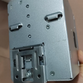
Clip a molla incorporata sul lato posteriore, montaggio senza attrezzi. Leva di rilascio in basso; spingere la leva verso il basso per rimuovere l'unità dalla guida.
❌ Il montaggio a parete tramite fissaggio diretto con viti NON è supportato. Solo montaggio su guida DIN.
Grado di protezione IP20, solo per installazione in armadio interno; non per l'impiego in campo nudo all'aperto.
- Orientamento di montaggio (Obbligatorio per prestazioni termiche & vita utile)
Convezione naturale senza ventola; l’orientamento non può essere cambiato arbitrariamente
- Posizione standard: montaggio verticale, terminali rivolti verso il basso (ingresso & terminali di uscita nella parte inferiore dell'unità), unità in posizione verticale. Questa è l'unica posizione ufficiale per il funzionamento continuo a pieno carico.
- ❌ Vietato: montaggio laterale orizzontale, sottosopra (terminali verso l'alto), montaggio inclinato. Gli orientamenti non standard compromettono il raffreddamento e richiedono un declassamento per carichi pesanti; non raccomandato per l'implementazione sul campo.
- Requisiti di spazio termico (Critico)
| Direzione | Autorizzazione richiesta | Osservazioni |
| Superiore | ≥50 mm | Consentire il flusso d'aria calda verso l'alto; la canalizzazione dei cavi non dovrà occupare questo spazio |
| Metter il fondo a | ≥50 mm | Presa d'aria fresca; la canalizzazione non deve bloccare l'area inferiore |
| Sinistra / Giusto | 0 mm | È possibile montare più unità strettamente adiacenti, non è richiesto alcuno spazio da un lato all'altro |
Non montare componenti che generano calore direttamente sopra l'alimentatore. Declassare il carico quando la temperatura dell'armadio è >60℃.
- Montaggio & Procedura di rimozione
- Agganciare il fermo superiore della clip a molla posteriore sulla guida DIN.
- Premere la sezione inferiore verso la guida finché non si sente un "clic" che conferma l'aggancio della clip.
- Agitare delicatamente per verificare che la sede sia stabile contro l'allentamento dovuto alle vibrazioni.
- Rimozione: Spingere verso il basso la leva di rilascio nera in basso, oscillare la parte inferiore verso l'esterno, sollevare l'unità dal binario.
Per ambienti ad alte vibrazioni: Montare i finecorsa della guida DIN per evitare spostamenti dovuti allo scorrimento.
- Cablaggio dei terminali & Valori di coppia
Eseguire il cablaggio con l'alimentazione scollegata.
Ingresso L/N/PE: 0.2-4 conduttori mm², coppia di serraggio 0,5-0,6 N·m
Uscita +24 V/0 V: Coppie di terminali doppi; parallela entrambe le coppie per correnti> 15 A per la mitigazione del calore
Terminali di segnale 13-14 (OK feedback), 15-16 (Accensione/spegnimento remoto): 0.14-1.5 Fili sottili da mm², coppia 0,5-0,6 N·m
- Montaggio per parallelo / Moduli di ridondanza
Questo alimentatore può essere installato fianco a fianco saldamente su guida DIN con moduli di ampliamento SITOP compatibili (ridondanza, respingente, moduli di selettività). Non è necessario alcun gap termico laterale tra l'alimentatore e i moduli aggiuntivi.
- Divieti di montaggio
- Non installare l'unità all'interno di un canale inferiore chiuso nell'armadio; lo spazio superiore/inferiore bloccato provoca l'arresto per sovratemperatura.
- Vietare l'installazione capovolta o orizzontale.
- Non posizionare dispositivi ad alta intensità di calore direttamente sopra l'unità.
- Solo per uso in armadietti interni; evitare ambienti non protetti all'aperto e con elevata umidità.
6EP1336-3BA10 (Alimentatore8200-20A) Parallelo / Linee guida sulla ridondanza + Elenco di controllo per la risoluzione dei problemi
- Funzionamento in parallelo per l'espansione della potenza (Nessun isolamento dei guasti)
Massimo. 5 unità identiche in parallelo per la condivisione automatica della corrente. Il Dip-switch A deve essere impostato su ON per attivare la curva caratteristica parallela.
- Prerequisiti hardware: Numero di ordinazione identico 6EP1336-3BA10; mantenere coerenti le revisioni dell'hardware, se possibile.
- Requisiti di cablaggio
Collegare +24 V e 0 V di ciascuna unità alla sbarra collettrice di uscita comune. I cavi positivi dovranno avere lunghezza e sezione trasversale identiche per equalizzare l'impedenza per una corretta condivisione della corrente.
Tutti i terminali negativi da 0 V devono essere messi a terra in comune; non è consentito il terreno galleggiante.
Interruttore automatico di ingresso comune consigliato per l'avvio-arresto sincronizzato.
Differenza di tensione di uscita a vuoto tra le singole unità ≤50 mV (le impostazioni di fabbrica soddisfano i requisiti; ricalibrare se i potenziometri sono stati regolati).
- Impostazioni dip-switch
A-ON: Modalità parallela (per l'espansione della potenza)
A-OFF: Modalità unità singola (impostazione di fabbrica; NON lasciare OFF per il funzionamento in parallelo)
- Limitazione: Il parallelo diretto per l'espansione della potenza non può isolare i guasti. Il cortocircuito su un'uscita farà crollare l'intera sbarra collettrice da 24 V. Non per la ridondanza con tolleranza agli errori.
- 1+1 Fornitura ridondante (Isolamento per guasti, Soluzione ingegneristica consigliata)
Due unità PSU8200-20A più modulo di ridondanza 6EP1961-3BA00 (PSE202U) per disaccoppiare l'isolamento. Se un alimentatore si guasta, il secondo si assume il carico ininterrottamente senza interruzione del bus 24V.
- Disposizione su guida DIN: Due alimentatori + modulo di ridondanza montato strettamente adiacente; terminali tutti rivolti verso il basso; non è richiesto alcuno spazio laterale.
- Punti chiave del cablaggio
- Alimenta due alimentatori da circuiti di ingresso indipendenti per la massima affidabilità di ridondanza.
- Collegare l'uscita 24 V+ di ciascun alimentatore ai due canali di ingresso del modulo ridondante.
- Collega in modo affidabile i terminali 0 V degli alimentatori e del modulo ridondante per la connessione equipotenziale; questo passaggio è obbligatorio.
- Instradare l'uscita del modulo ridondante alla sbarra di carico di campo da 24 V.
- Il modulo ridondante fornisce contatti relè di guasto, collegare all'ingresso digitale del PLC per l'allarme di guasto di ridondanza.
- Impostazione dip-switch: Per configurazione ridondante, posizionare il dip-switch A degli alimentatori su OFF (modalità unità singola). NON attivare la modalità parallela.
⚠️ Non implementare mai la ridondanza tramite parallelo diretto senza modulo di ridondanza. Il cortocircuito interno di un'unità causerà il crash dell'intero sistema a 24 V.
III. Tabella di riferimento degli indicatori LED
| Stato del LED | Senso | Azione |
| Verde fisso acceso | Unità sana, uscita>20V | Funzionamento normale |
| Giallo acceso fisso | Sovraccarico / limite di corrente costante attivo, Power‑Boost attivato | Controllare la corrente di carico; individuare un cortocircuito parziale; ridurre il carico |
| Rosso fisso acceso | Arresto con blocco (cortocircuito / sovratensione / sovratemperatura) | Spegnimento per ≥60 secondi, o disattivare il telecomando 15‑16 per ≥5 s per il ripristino; eliminare il cortocircuito / causa principale del surriscaldamento |
| Tutti i LED SPENTI | Nessuna alimentazione in ingresso; fusibile interno bruciato | Verificare la tensione di ingresso CA/CC e la messa a terra PE |
Dip-switch B: Selezione della risposta al cortocircuito
B-OFF (impostazione di fabbrica): Modalità a corrente costante, 23 Una limitazione di cortocircuito; ripristino automatico dopo la risoluzione del guasto; LED giallo acceso
B-ON: Modalità di arresto con blocco; l'uscita si interrompe in caso di cortocircuito; LED rosso acceso; è necessario il ripristino del ciclo di accensione
- Elenco di controllo per la risoluzione dei problemi
- Nessuna indicazione LED dopo l'accensione, uscita nulla
- Misurare la tensione in ingresso L-N: CA 85-275 VCA / CC 88-350 V CC; confermare il collegamento della terra di protezione PE.
- Controllare la coppia del terminale a vite per contatti allentati; verificare lo stato dell'interruttore a monte.
- Se la tensione in ingresso è normale ma nessun LED si accende: Guasto al fusibile di ingresso interno; guasto hardware, sostituire l'alimentatore.
- LED giallo acceso fisso, l'uscita scende a 18-20 V
- La corrente di carico supera 20 A → modalità di limitazione della corrente costante; misurare la corrente di carico totale effettiva.
- Cortocircuito parziale o danno all'isolamento del cavo sul lato uscita. Scollegare tutti i carichi; verificare se la tensione ritorna a 24 V in condizioni di assenza di carico.
- Caduta di tensione eccessiva causata da cavi a sezione sottile a lunga distanza; utilizzare conduttori di uscita di dimensioni maggiori o aumentare leggermente la tensione di uscita tramite potenziometro per la compensazione.
- Spegnimento con blocco del LED rosso all'accensione, nessuna uscita
- Cortocircuito sul lato uscita. Prova con tutti i carichi scollegati; il normale comportamento a vuoto indica un cortocircuito del carico esterno.
- Temperatura ambiente eccessiva dell'armadio, Spazio di ventilazione superiore/inferiore insufficiente che attiva la protezione da sovratemperatura; confermare ≥50mm superiore & gioco del fondo.
- Sovratensione in uscita: Ensure potentiometer is not accidentally adjusted above 28.8 V; confirm downstream-device voltage withstand rating.
- Reset procedure: Power-off ≥60 s then re-energize; or open Remote 15-16 for ≥5 s then close again.
- Abnormal 24V-OK (13-14) relay contact behavior
Terminali 13-14 are potential-free dry contacts, closed only when output>20 V. Valutazione dei contatti: DC30 V, massimo. 0.1 UN. For PLC digital-input signal only; do NOT drive contactor coils or high-power loads.
- Poor current-sharing in parallel; one unit runs excessively hot
- Dip-switch A not set to ON.
- Large discrepancy in length / cross-section of positive output cables.
- No-load output voltage difference>50 mV between units; fine-tune potentiometers for matching.
- Loose 0 V wiring leading to equipotential mismatch.
- Remote terminals 15-16 fail on / off control
15-16 are potential-free contacts: Short-circuit = output enable; circuito aperto = uscita disabilitata. Non è richiesta alcuna fornitura esterna.
Se la funzione remota non è utilizzata: Mantenere 15-16 cortocircuitato con ponticello di fabbrica; non rimuovere il ponticello.
- Raccomandazioni per la messa in servizio
- Messa in servizio del nuovo armadio: Accendere prima senza carico; confermare l'uscita 24 V e il LED OK verde fisso; collegare i carichi in modo incrementale.
- Messa in servizio del sistema di ridondanza: Scollegare una sorgente di ingresso alla volta; verificare la commutazione senza interruzioni con interruzione del carico pari a zero.
- Applicazioni in armadi ad alta temperatura: Applicare una riduzione del carico al di sopra di 60 ℃ ambiente; evitare il funzionamento continuo a 20 A completi.





NH42-63-318x560.png "Commutatori automatici di tipo PC CHINT (ATS)NH42-63/4SZ")



