 Contattore,interruttore automatico,sensore,Codificatore,PLC,Convertitore

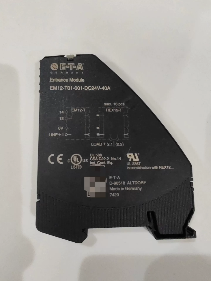


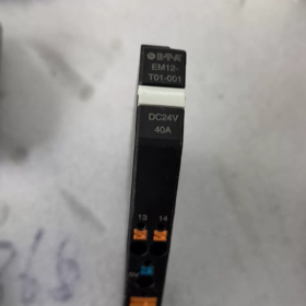
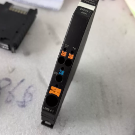
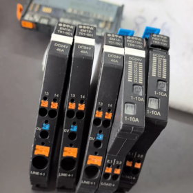
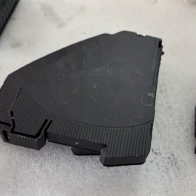
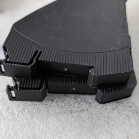
(Modello completo: EM12-T01-001-DC24V-40A)
- Informazioni di base
Marca: ETA Germania
Serie: REX12-T Sistema di distribuzione dell'alimentazione CC modulare
Nome del prodotto: Modulo di alimentazione principale / Modulo di distribuzione del bus di alimentazione
Applicazione: Unità di ingresso principale per il sistema di protezione elettronica del circuito REX12-T, che distribuisce uniformemente l'alimentazione del bus positivo CC 24 V a una fila completa di protezioni multicanale
- Scomposizione del codice modello
"EM12-T01-001".
- EM12: Serie di moduli di alimentazione abbinati a REX12
- T: Tipo di segnale analogico standard (senza comunicazione IO-Link; dotato di contatto di allarme collettivo passivo Si)
- 01: Versione con alimentazione a singolo polo positivo
- 001: Versione hardware base con DC24V standard, 40Una specifica
Specifiche complete del suffisso:
DC24V: Tensione operativa nominale
40UN: Corrente massima totale in ingresso del modulo
- Parametri elettrici principali
| Elemento parametro | Valore delle specifiche |
| Tensione nominale | DC24V, intervallo operativo CC 18 ~ 30 V |
| Corrente di ingresso totale massima | 40UN |
| Consumo di energia statica a vuoto | Tipico 10 mA |
| Protezione da inversione di polarità | Diodo anti-inversione incorporato |
| Buffer di caduta di tensione | 10SM (nessun falso allarme per caduta di tensione a breve termine) |
| Contatto allarme Si | Contatto passivo normalmente aperto; carico CC 30 V/0,5 A, minimo pilotaggio 10V/1mA |
| Metodo di cablaggio | Morsetti a molla push-in senza attrezzi, filo di rame massimo 10 mm² |
| Tensione di tenuta dielettrica | Ingresso/Uscita AC2000V per 1 minuto |
| Resistenza di isolamento | ≥100 MΩ @500 VCC |
- Ambientale & Dimensioni meccaniche
Montaggio: Guida DIN standard da 35 mm
Dimensioni complessive: L12,4 mm × A 98 mm × P80 mm
Temperatura operativa: -25℃ ~ +60 ℃
Temperatura di stoccaggio/trasporto: -40℃ ~ +85 ℃
| Classe di protezione | IP20 (solo per uso interno del mobile) |
| Certificazioni | UL508A, CSA, CE, RoHS, PORTATA |
- Funzioni principali
- Distribuzione centrale dell'energia sugli autobus
Collegare l'alimentatore esterno da 24 V CC a questo modulo. Le sbarre metalliche integrate sul lato forniscono automaticamente alimentazione in parallelo a tutti i protettori di circuito REX12-T collegati in serie sul lato destro della guida senza cablaggio tra moduli.
- Allarme di guasto collettivo globale (Si Contatto)
Una volta che una qualsiasi protezione REX12 interviene a causa di sovraccarico o cortocircuito, il contatto Si passivo interno si apre. Può essere collegato al PLC o alle spie luminose per realizzare un segnale di guasto unificato per l'intera fila di circuiti.
- Protezione da inversione di polarità & Resistenza alle fluttuazioni di tensione
I poli di alimentazione positivi e negativi invertiti non danneggeranno il modulo. Il buffer di caduta di tensione di 10 ms previene i falsi allarmi causati dalla caduta di tensione istantanea degli alimentatori a commutazione.
- Compatibilità di espansione
Collegamento in serie illimitato degli interruttori elettronici REX12 mono/bicanale sul lato destro. È possibile collegare più moduli EM12-T01 in parallelo per espandere la capacità di corrente totale.
- Scenari applicativi tipici
24Distribuzione del carico VCC negli armadi di controllo industriali: Uscite del PLC, servoazionamenti, sensori, elettrovalvole, robot, distribuzione di energia DC a bordo per il trasporto ferroviario, quadri di comando elettrici per macchine edili.
- Confronto con i modelli della stessa serie
- EM12-T01-001: Tipo analogico standard con soli contatti di allarme passivi, nessuna funzione di comunicazione
- EM12D-T: Versione di comunicazione intelligente che supporta IO-Link/Modbus RTU, in grado di leggere la corrente del canale e i codici di errore
- EM12-T00: Versione semplificata senza contatti di allarme
- PM12-T: Modulo di espansione potenziale per estensione sbarre multifila
- Nome dell'ordine completo standard
Modello di ordine completo: EM12-T01-001-DC24V-40A
SKU delle azioni di riferimento per i distributori: DigiKey302-1471-ND, RS 175-0362
Specifiche di installazione complete per E-T-A EM12-T01-001-DC24V-40A
- Modulo di montaggio standard
Montaggio standard esclusivo: Guida DIN standard da 35 mm TH35-7.5 (EN50022)
Nessun fissaggio con viti di base o opzioni di montaggio a parete; solo installazione ad aggancio su guida DIN. È consentito solo il montaggio orizzontale affiancato; verticale, è vietata l'installazione capovolta o inclinata.
Dimensioni complessive: L12,4 mm × A 98 mm × P80 mm, larghezza del singolo modulo, collegati senza soluzione di continuità fianco a fianco con gli interruttori REX12 della stessa serie.
- Fasi di installazione del clip-in su guida DIN (È richiesta l'operazione di spegnimento!)
- Preelaborazione ferroviaria
Adottare la guida TH35 standard in acciaio/alluminio e sbavare dopo il taglio. Montare la guida orizzontalmente con una distanza tra le viti di fissaggio ≤250 mm per evitare vibrazioni e deformazioni.
- Modulo a clip
Agganciare lo slot superiore del modulo al bordo superiore della guida DIN, premere delicatamente la parte inferiore del modulo fino a quando a “clic” il suono indica il bloccaggio completo. Verificare che non vi siano allentamenti verticali e che il modulo non possa essere sollevato verso l'alto.
- Regole di layout del sistema principale
EM12-T01 deve essere installato all'inizio dell'estrema sinistra dell'intero circuito REX12 come punto di ingresso dell'alimentazione principale;
Montare la sbarra metallica laterale sulla destra del modulo contro la sbarra collettrice sinistra del successivo interruttore REX12, chiudere il fermo di collegamento laterale per realizzare l'alimentazione del bus parallelo;
Un singolo EM12-T01 supporta il massimo 40 interruttori elettronici REX12 collegati in serie;
Espansione multicircuito: Più moduli EM12-T01 forniranno alimentazione in modo indipendente; è vietata l'interconnessione diretta affiancata di più moduli EM12.
- Specifica di smantellamento
Scollegare prima l'alimentazione principale. Utilizzare un cacciavite a testa piatta per fare leva sul fermo inferiore e sollevare il modulo verso l'alto per rimuoverlo. È severamente vietato smontare i moduli collegati in serie sotto tensione, che interromperà la sbarra collettrice e causerà un'interruzione dell'alimentazione del circuito.
- Installazione del cablaggio (Compatibile con ingresso cavi dall'alto/dal basso)
Zone terminali & Specifiche del calibro del filo
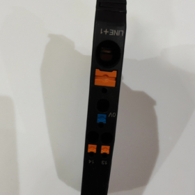
- LINEA+ (24V ingresso positivo principale, alimentazione primaria)
Filo applicabile: 0.5~ Filo di rame multifilare da 10 mm², Morsetto a vite M4, coppia consigliata 1,2 N·m
- 0V (Terminale negativo CC comune)
Filo applicabile: 0.14~2,5 mm²
- E (Contatto allarme guasto collettivo passivo)
Filo applicabile: 0.14~2,5 mm², carico massimo CC 30 V/0,5 A
Requisiti di cablaggio
Sono disponibili ingressi cavi sia dall'alto che dal basso; selezionare la direzione del cablaggio in base alla disposizione dell'armadio;
Cavi di ingresso principali pesanti (≥6mm²) devono essere instradati separatamente dai cavi del segnale Si in diversi condotti per cavi per ridurre le interferenze;
Chiudere i fermi di interconnessione laterali dei moduli solo dopo aver completato tutto il cablaggio, quindi accendere l'alimentazione.
- Dissipazione del calore & Requisiti di installazione della spaziatura
- Lasciare uno spazio di ventilazione verticale di ≥50 mm tra i componenti superiore e inferiore sulla stessa guida DIN;
- Questo modulo è un'unità di alimentazione ad alta corrente da 40 A; non montarlo vicino a componenti che generano calore come alimentatori ad alta potenza, inverter e contattori;
- Nessuna fessura di isolamento obbligatoria per moduli multipli densamente disposti, ma la temperatura ambiente dell'armadio deve essere controllata ≤60℃;
- All'interno dell'armadio deve essere garantita la ventilazione per convezione naturale; installare ventole di raffreddamento per armadi sigillati senza ventilazione.
- Installazione rinforzata per le vibrazioni & Condizioni di lavoro dure
Per scenari con vibrazioni elevate, comprese le macchine utensili, trasporto ferroviario e macchine edili:
- Installare i finecorsa della guida DIN su entrambe le estremità della guida per impedire lo scorrimento orizzontale dei moduli;
- Attacca dei cuscinetti ammortizzanti in gomma da 3 mm al binario posteriore per ridurre la risonanza;
- Ricontrollare regolarmente la coppia del terminale e lo stato di bloccaggio del dispositivo di chiusura.
- Divieti di installazione severi
- Verticale, è vietata l'installazione capovolta o inclinata oltre i 45°, che deteriora la dissipazione del calore e attiva la protezione dal surriscaldamento;
- Collegamento in tempo reale, è vietato scollegare o smontare i moduli collegati in serie; L'interruzione dell'alimentazione alla sbarra causerà l'arresto dell'apparecchiatura;
- È vietata l'installazione dell'EM12 al centro o sul lato destro del circuito REX12, con conseguente interruzione dell'alimentazione del bus;
- Sono vietati cavi di ingresso più sottili di 0,5 mm² o più spessi di 10 mm², con conseguente piegatura del terminale allentato e surriscaldamento;
- Installazione diretta senza protezione in ambienti polverosi, sono vietati ambienti con nebbia d'acqua o condensa (IP20 solo per uso interno armadio);
- La corrente di carico totale a lungo termine del singolo EM12 non dovrà mai superare il valore nominale di 40 A.
- Materiali ausiliari consigliati per l'installazione
- Fermi di fissaggio estremità guida DIN (evitare che il modulo scivoli);
- Cacciavite dinamometrico M4 (coppia di serraggio terminale unificato 1,2 N·m);
- Terminali a crimpare per cavi multifilari per evitare cortocircuiti causati da fili di rame sparsi;
- Separazione dei condotti dei cavi: Instradare i cavi principali dell'alimentazione da 24 V e i cavi del segnale di allarme Si separatamente.
Parametri di temperatura di E-T-A EM12-T01-001-DC24V-40A (Manuale del produttore originale standard)
- Temperatura operativa ambientale normale
Intervallo operativo standard: -30 ℃ ~ +60 ℃, è severamente vietata la formazione di condensa durante il funzionamento (IN 60204-1 standard di applicazione dell'armadio)
23℃ temperatura ambiente: È consentito il funzionamento continuo a pieno carico a 40 A
40℃: Declassare la corrente nominale a 95% (38UN)
50℃: Declassare la corrente nominale a 90% (36UN)
60℃: Declassare la corrente nominale a 85% (34UN)
Installazione fitta affiancata di più moduli: Ulteriore declassamento della corrente a 80% del valore sopra indicato
- Declassamento della temperatura in altitudine (Condizioni di lavoro ad alta quota)
≤2000m: Supporto completo per range operativo -30~+60℃
3000M: La temperatura ambiente massima consentita è ridotta a +55℃
4000M: La temperatura ambiente massima consentita è ridotta a +50℃
- Magazzinaggio & Temperatura di trasporto (Stato di spegnimento)
Temperatura di conservazione: -40 ℃ ~ +70 ℃ (con imballo originale di fabbrica)
Limite di archiviazione a lungo termine: -40℃ ~ +85 ℃ (solo esposizione a breve termine, nessuna accensione consentita)
- Installazione & Cablaggio della temperatura ambiente
Ambiente operativo per assemblaggio e cablaggio: +5 ℃ ~ +60 ℃. Lo smontaggio e il montaggio del terminale non sono consigliati al di sotto di 5 ℃; i fili freddi tendono a sfilacciarsi e portare a una coppia terminale instabile.
Limitazioni d'uso supplementari
- La classificazione IP20 si applica solo all'uso interno dell'armadio; non può essere esposto direttamente ad ambienti esterni con temperature estreme, acqua nebulizzata o polvere;
- Per armadi stagni senza ventole di raffreddamento forzato, Si consiglia di controllare la temperatura ambiente dell'armadio a lungo termine ≤50℃;
- Non si verifica alcun guasto funzionale quando si avvia a una temperatura bassa di -30 ℃, ma preriscaldare a vuoto per un periodo prima del funzionamento a pieno carico a freddo.





NH42-63-318x560.png "Commutatori automatici di tipo PC CHINT (ATS)NH42-63/4SZ")



