 Contattore,interruttore automatico,sensore,Codificatore,PLC,Convertitore

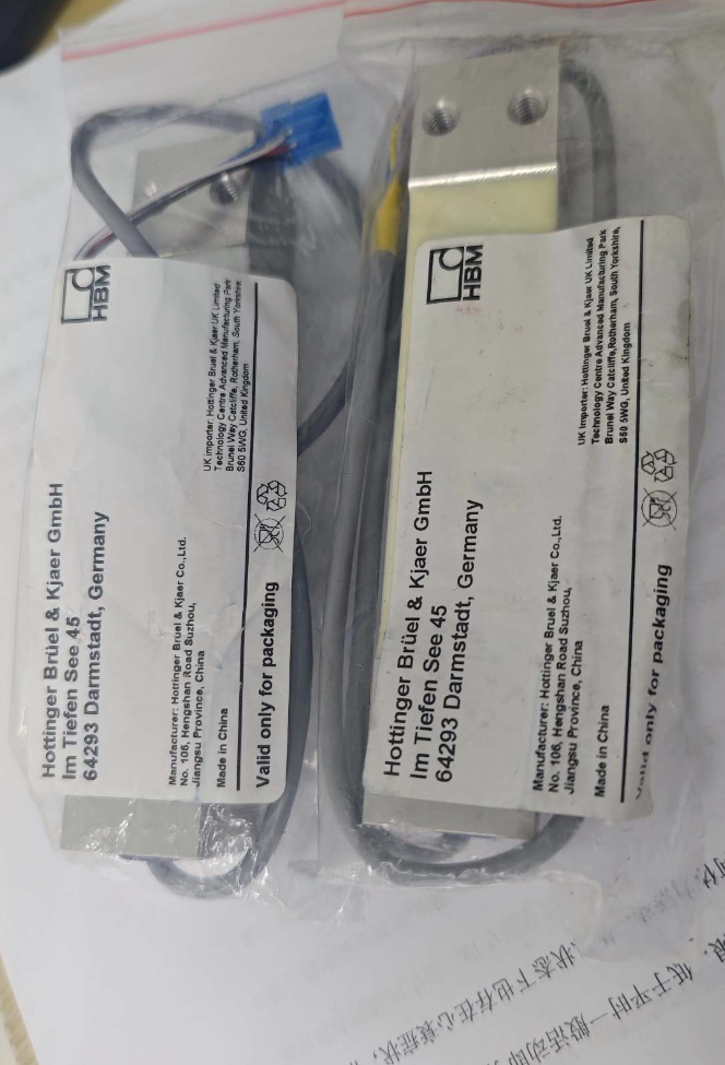

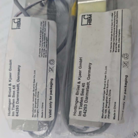
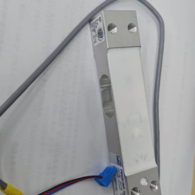
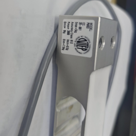
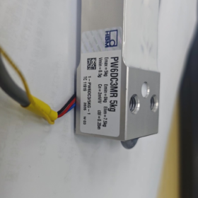
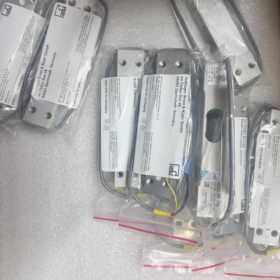
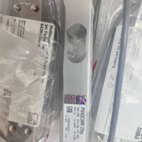
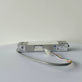
PW6DC3MR/XXkg
PW6D: Serie di prodotti, single-point type optimized for high-speed dynamic weighing
C3: Accuracy class of 3,000 verification divisions in accordance with OIML R60
MR = Multi-Range: Compared with standard C3 version, it supports a smaller minimum verification interval, suitable for multi-range weighing instruments
XXkg: Capacità nominale (3/5/10/15/20/30/40kg)
Complete ordering model example: 1-PW6DC3MR/10KG-1
- Specifiche principali
- Capacity Options
3kg, 5kg, 10kg, 15kg, 20kg, 30kg, 40kg
- Parametri Elettrici
Potenza nominale: 2.0 mV/V
Bridge Input Resistance: ~350 Ω
Tensione di eccitazione consigliata: 5~12 V DC (Massimo. 15 A DC)
Costruzione: 6-wire design (cable can be trimmed) to eliminate measurement error caused by cable voltage drop; compatible with 4-wire instruments
Resistenza di isolamento: >2000 MΩ
- Precisione & Certificazioni
OIML R60 C3MR, nLC=3000 divisions
Off-center load compensation compliant with OIML R76; maximum platform dimension for single load cell: 300×300 mm
Non linearità / Isteresi / Ripetibilità: ≤±0.017 %FS
- Meccanico & Specifiche ambientali
Materiale: Lega di alluminio
Classe di protezione: IP67
Rated Deflection: 0.18~0.29 mm (High stiffness, risposta dinamica veloce)
Compensated Temperature Range: -10 ℃ ~ +40 ℃
Intervallo di temperatura operativa: -10 ℃ ~ +50 ℃
Sovraccarico sicuro: 150%FS; Ultimate Overload: 300%FS
Mounting Bolt: M6; Recommended Tightening Torque: 10 N·m
- Vantaggi principali
✅ Optimized for dynamic weighing: High natural frequency, ideal for high-speed checkweighing and volumetric filling
✅ Built-in off-center load compensation to minimize platform eccentricity error
✅ IP67 sealing, applicable in dusty and humid production environments
✅ 6-wire shielded cable ensures stable signal for long-distance wiring
✅ MR multi-range variant supports smaller verification intervals, compliant for legally verified commercial weighing equipment
- Applicazioni tipiche
Inline checkweighers, weight sorting machines
Small-scale automatic packaging, polvere & particle filling equipment
Industrial platform scales, multi-head combination weighers
Dynamic weight monitoring on automated production lines
- Definizione di cablaggio (Standard 6-Wire Shielded Cable)
| Segnale | Typical Wire Color |
| +Exc Excitation Positive | Blu |
| -Exc Excitation Negative | Nero |
| +Sense Sense Positive | Verde |
| -Sense Sense Negative | Grigio |
| +Sig Signal Positive | Bianco |
| -Sig Signal Negative | Rosso |
| Scudo | Green/Yellow |
For 4-wire instruments: Short-circuit +Sense to +Exc, and -Sense to -Exc
- Stessa serie & Alternative References
- PW6DC3: Standard C3 accuracy (non-MR), costo inferiore, cannot support multi-range small verification intervals
- PW2DC3MR: Smaller-size single-point load cell from HBM, with smaller maximum allowable platform size
- Alternative domestiche: Single-point C3 load cells from Zemic, UN&D, Zhonghang Electronic Measuring Instruments. Verify mounting hole layout, mV/V rating and maximum platform size before replacement.
- Precauzioni per l'installazione
- Mounting surfaces must be flat and rigid. Do not weld or strike the load cell body.
- Tighten M6 bolts strictly at 10 N·m to avoid thread stripping on aluminum housing.
- Load shall be applied vertically downward; avoid lateral force and torque impact.
- Prevent mechanical bending and tension at the cable outlet; single-end grounding is recommended for shielding.
Complete Load Cell Selection Guide (Illustrated with HBM PW6DC3MR Single-Point Load Cell)
Fare un passo 1: Confirm Mechanical Structure Type (Highest Priority)
Match load cell structure according to load condition:
| Scenario applicativo | Tipo consigliato | Applicability for PW6DC3MR |
| Single load cell supporting one platform, checkweigher, small packaging scale | Single-Point Load Cell ✅ | PW6DC3MR is a single-point type. Built-in eccentricity compensation; one platform requires only one load cell |
| Material hoppers, bins, multi-cell platform scales | Shear Beam / Trave a sbalzo | ❌ Not applicable to PW6D |
| Tension weighing, hanging scales | S-Beam Load Cell | ❌ Not applicable to PW6D |
| Heavy-duty truck scales, tank weighing | Column / Spoke Load Cell | ❌ Not applicable to PW6D |
Hard restriction of PW6DC3MR: Maximum platform dimension: 300×300 mm. Platform exceeding this size will cause excessive eccentricity error.
Fare un passo 2: Calcolo della capacità (Most Common Pitfall in Selection)
Formula di calcolo
Rated Capacity of Load Cell ≥ (Platform Dead Weight + Maximum Product Weight) × Safety Factor
Stable static weighing: Safety factor 1.2~1.3
Dynamic checkweighing, material drop impact, vibrating production line: 1.5~2.0 (1.5 raccomandato)
Esempio pratico (PW6DC3MR)
Platform dead weight = 1.5kg, maximum product weight = 10kg, inline dynamic checkweighing:
Total load = 1.5 + 10 = 11.5kg; 11.5 × 1.5 = 17.25kg
Priority selection: PW6DC3MR/20KG. Avoid 15kg (insufficient margin) and excessive 30kg capacity (poor resolution for light loads).
⚠️ Two critical rules:
- Do not operate continuously near full capacity;
- Do not oversize capacity excessively, which degrades resolution for low-weight measurement.
Fare un passo 3: Accuracy Class Selection (C3 / C3MR / C6 Comparison)
Take HBM PW6D series as example:
- C3: Standard 3000 divisions, for general industrial weighing, unable to achieve ultra-small verification intervals
- C3MR (Il tuo modello): Multi-Range variant, OIML R60 certified, supports smaller minimum verification interval (Vmin)
✅ Suitable for equipment requiring legal metrology certification, high-speed checkweighing, volumetric filling and high display resolution (gram-level measurement)
- C6: 6000 divisions, maggiore precisione, costo più elevato, stricter requirements for mounting rigidity and operating environment
Quick Selection Rule for C3 vs C3MR
Equipment requires commercial metrological certification, high-precision checkweighing, small scale interval (gram level) → PW6DC3MR
Only internal process monitoring, no weighing certification required, loose accuracy requirements → PW6DC3 (versione standard)
Key accuracy indicators to review: Non linearità, isteresi, ripetibilità, creep, temperature drift error.
Fare un passo 4: Ambiente operativo, Materiale & Classe di protezione
- Materiale
PW6DC3MR: Lega di alluminio; suitable for dry standard food and automated workshops.
For washdown, humid or corrosive / salt spray environments: Prefer stainless steel single-point load cells.
- Classe di protezione
PW6D: IP67, dust-proof and splash-proof; NOT for permanent submersion.
For fully washed equipment or underwater installation: IP68 hermetically sealed load cells are required.
- Intervallo di temperatura
Compensated range: -10~+40℃; prolonged operation outside this range leads to severe zero drift. Custom wide-temperature models needed for extreme temperature conditions.
- Explosion Protection: For hazardous explosive areas, use intrinsically safe certified load cells. Standard PW6DC3MR is non-explosion-proof.
Fare un passo 5: Electrical Parameter Matching with Instrument
- Sensibilità: PW6DC3MR = 2.0 mV/V, the most common specification for industrial weighing; confirm instrument compatibility.
- Tipo di cablaggio: PW6D adopts 6-wire (with Sense feedback lines)
Instrument supporting 6-wire: Full wiring to eliminate cable voltage drop
Instrument only supporting 4-wire: Short-circuit +Sense to +Exc, -Sense to -Exc
- Excitation Voltage: Recommended 5~12 V DC, massimo 15 A DC
- Bridge Resistance: ~350 Ω input resistance, compatible with standard weighing transmitters
Fare un passo 6: Mechanical Dimension Verification (Easily Overlooked)
- Lunghezza totale, altezza, mounting hole pitch, thread specification (PW6D uses M6 mounting bolts)
- Check mechanical installation space
- Ensure vertical load transmission; structure design shall eliminate lateral force and torque
PW6D mounting torque standard: M6 bolt tightening torque 10 N·m. Aluminum housing risks thread damage under excessive torque.
Fare un passo 7: Distinguish Dynamic / Static Application Scenarios
Static Weighing (Warehouse Platform Scale): Standard C3 is sufficient; prioritize long-term zero stability
Dynamic Weighing (Inline Checkweigher, Online Sorting): PW6DC3MR preferred; optimized high natural frequency, fast response and vibration resistance
Common Selection Mistakes Checklist
❌ Only consider maximum product weight without including platform dead weight
❌ Use PW6D single-point load cell for platform larger than 300×300 mm, resulting in excessive eccentricity error
❌ Adopt safety factor of only 1.2 under dynamic impact, leading to elastic element fatigue and permanent damage
❌ Purchase standard C3 instead of C3MR when weighing certification is required, failing to meet minimum scale interval requirement
❌ Select aluminum IP67 load cell for washdown humid environment, leading to long-term water ingress and premature failure
❌ Oversized capacity causes unstable readings and poor resolution for light products
Quick Selection Template (Ready for Direct Use)
- Struttura: Single-Point ✅ (Platform ≤300×300 mm)
- Total Load: Platform ____kg + Max Product ____kg = ____kg × Safety Factor ____ = ____kg → Selected Model PW6DC3MR/____kg
- Precisione: Metrological certification required? Yes → C3MR; No → C3
- Ambiente: Dry workshop, IP67 acceptable; Lavaggio / corrosive environment → switch to stainless steel load cell
- Elettrico: Instrument supports 2.0 mV/V; confirm 6-wire or 4-wire wiring
- Installazione: Verify dimension, M6 mounting space, vertical force transmission structure
How to Determine the Mounting Position of Load Cells
Explanation based on HBM PW6DC3MR single-point load cell (single-cell platform); general rules for multi-cell weighing platforms are also included.
- Distinguish Two Structural Types: Single-Point vs Multi-Cell
(1) Single-Point Load Cell (PW6DC3MR, single cell supporting one platform)
Single-point load cells feature built-in off-center load compensation.
Standard mounting position: Geometric center of the platform bottom
✅ Optimal arrangement:
Align the load-bearing hole center of the load cell with the length and width center of the platform.
Maximum allowable platform dimension: 300 × 300 mm (PW6D specification limit)
⚠️ Critical Restrictions:
If the load cell deviates from the center:
Eccentricity error increases
Inconsistent readings when weight is placed at four corners
Even centered installation cannot compensate error if platform exceeds manufacturer’s maximum dimension limit
Practical method: Draw two diagonals of the rectangular platform; the intersection is the center mounting position.
(2) Multi-Cell Structure (3/4 Cantilever/Shear Beam Load Cells, Platform Scales, Storage Hoppers)
Mounting position follows the principle of even load distribution according to center of gravity
- Rectangular platform with four load cells: Symmetrically arranged near four corners
- Circular storage bin with three load cells: Evenly distributed in an equilateral triangle layout
- Target: Load carried by each load cell shall be as uniform as possible under empty and full load conditions
- Five Universal Principles for All Weighing Systems
Principio 1: The combined center of gravity must fall within the support envelope of load cells
- Unloaded condition: Platform self-weight center of gravity lies within the support area
- Fully loaded condition: When material is placed at maximum eccentricity, the overall combined center of gravity remains within the support envelope
If the center of gravity moves outside the support region: Risk of platform tipping, and the load cell bears huge lateral force and torque, leading to permanent damage.
Principio 2: Eliminate Lateral Force and Torque on Load Cells
Load cells shall only bear vertical compressive force
❌ Prohibited conditions:
Lateral component force generated by skewed mounting position
Torque induced by insufficient rigidity of support frame
✅ Soluzione:
Design mechanical stops for horizontal restriction. Maintain tiny vertical clearance; stops shall not carry vertical load.
Principio 3: Ensure Vertical Force Transmission
The load-bearing surface of the load cell must be parallel to the bottom surface of the weighing platform.
Mounting base must be flat and rigid; avoid thin plate suspension and local concentrated contact.
PW6DC3MR aluminum housing forbids point contact loading.
Principio 4: Avoid Strong Vibration Sources and Thermal Expansion Tension
Mounting position selection:
Keep distance from strong vibration sources such as motors and conveyor rollers
Thermal expansion/contraction of long frames may pull the load cell; sliding support structure is required when necessary
Principio 5: Prevent Tensile Stress on Cable Outlet
The cable outlet of PW6DC3MR is at the end of the sensor.
Arrangement requirement: Reserve slack cable loops; avoid tension and repeated bending at the cable root to prevent internal wire breakage.
- Step-by-Step Positioning for Single-Point Platform (PW6DC3MR)
- Measure external platform dimension: Length L × Width W
- Calculate center coordinates: L/2, W/2
- Align the load-bearing hole center of the load cell with the calculated center point
- Platform dimension verification:
≤300×300 mm: Normal centered installation
>300×300 mm: PW6D cannot be used. Switch to larger single-point load cell or multi-cell solution
- Weight test verification:
Place calibration weights sequentially at four corners of the platform and observe reading deviation.
Excessive four-corner error indicates either offset load cell position or oversize platform.
- Four-Corner Positioning Operation for Multi-Cell Platform (4 Load Cell Example)
- Symmetric layout; four support points form a rectangle
- Leave proper margin between support points and platform edge; avoid placing too close to edges
- Rough leveling under empty load with preloading
- Perform four-corner error calibration after loading weights at each corner
- Install mechanical stops to prevent platform sliding under impact
- Common Mounting Position Errors
- Single-point load cell installed away from platform center → inconsistent readings at four corners
- Oversize platform still using PW6D single-point load cell → excessive eccentricity error
- Insufficient rigidity of support frame; frame deformation under load induces torque on load cell
- Locked mechanical stops; thermal expansion creates additional force leading to continuous zero drift
- Load cells arranged too close to edges; center of gravity moves outside support envelope when material is placed eccentrically
- Belt tension creates horizontal pulling force transferred to load cell on inline checkweighers (Independent frame required to isolate belt tension)
- Additional Advice for Your Equipment (Checkweigher with PW6DC3MR)
For inline checkweighers: The belt conveyor frame shall not be rigidly fixed to the weighing platform.
Conveyor motor and belt tension produce continuous horizontal pulling force.
Recommended solution: Only the weighing platform carries products; the conveyor frame stands independently on the ground to isolate horizontal force.





NH42-63-318x560.png "Commutatori automatici di tipo PC CHINT (ATS)NH42-63/4SZ")



