 Contattore,interruttore automatico,sensore,Codificatore,PLC,Convertitore

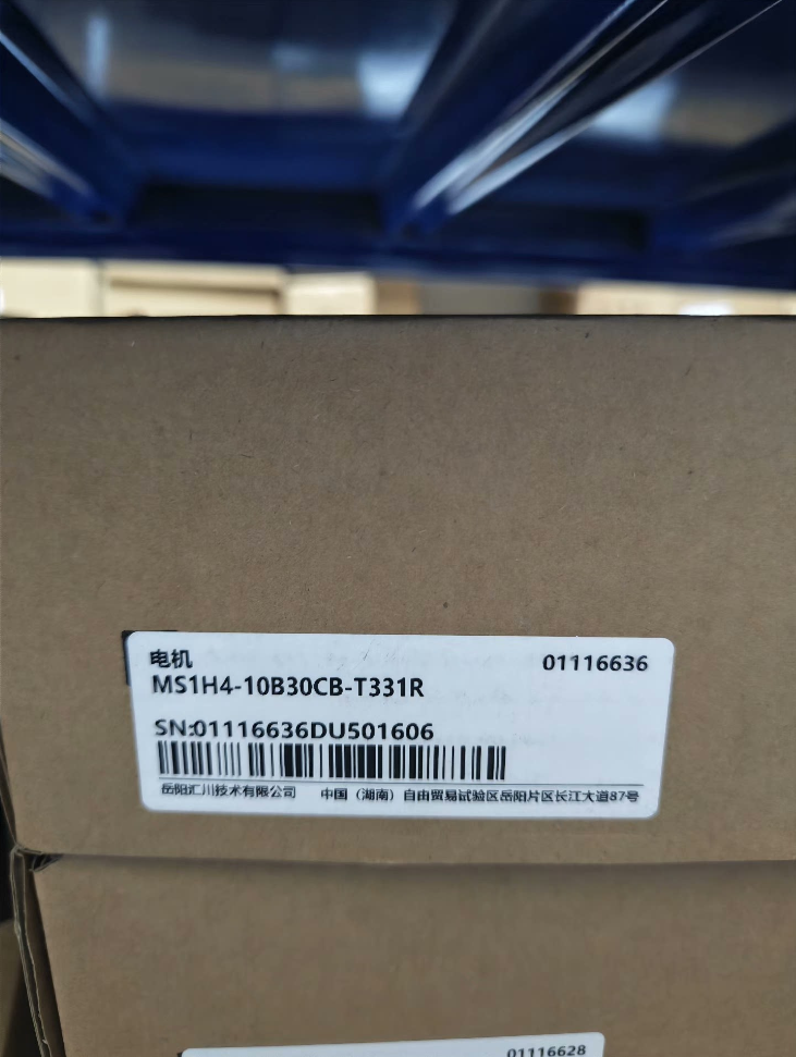

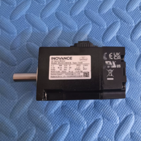
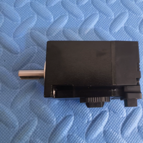
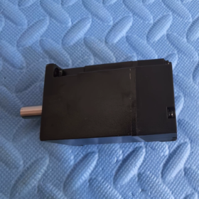
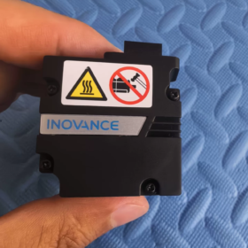
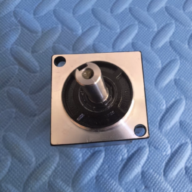
MS1H4-10B30CB-T331R
| Segmento | Definizione |
| MS1 | Serie MS1 Generale Servomotore |
| H4 | Inerzia media, Piccola capacità |
| 10B | Potenza nominale: 10×10 = 100W (0.1kW) |
| 30C | Velocità nominale: 30×100 = 3000 giri/min |
| B | Classe di tensione: AC220V mono/trifase |
| T3 | 18-bit Assoluto multigiro Codificatore |
| 3 | Configurazione dell'albero: Con sede per chiavetta + Filettatura interna all'estremità dell'albero |
| 1 | Accessorio: Con paraolio, Senza freno di stazionamento elettromagnetico |
| R | Versione con flangia standard |
Nota di distinzione: A3 = Encoder assoluto multigiro a 23 bit; T3 = Encoder assoluto multigiro a 18 bit. I cavi sono meccanicamente intercambiabili, ma la risoluzione è diversa; i parametri non devono essere utilizzati senza riconfigurazione.
- Principali Specifiche Elettriche
| Articolo | Valore |
| Potenza nominale | 100W / 0.1kW |
| Coppia nominale | 0.32 N·m |
| Coppia di picco | 1.12 N·m (350% Sovraccarico) |
| Velocità nominale | 3000 giri/min |
| Velocità massima | 7000 giri/min |
| Corrente nominale | 1.27 UN |
| Corrente di picco | 4.78 UN |
| Momento di inerzia del rotore | 0.072 ×10⁻⁴ kg·m² |
| Dimensioni della flangia del telaio | 40 mm |
| Codificatore | 18bit Encoder assoluto multigiro |
| Freno di stazionamento | Non attrezzato |
| Classe di protezione | IP67 (Esclusa l'area della tenuta dell'albero) |
| Tipo di servizio | S1 Funzionamento continuo |
- Servoazionamenti compatibili
✅ Abbinamenti consigliati:
Serie SV660PS (Corrente principale)
Serie SV670PS
Non direttamente compatibile con le unità IS620 legacy. Il cavo adattatore dell'encoder è obbligatorio se si utilizza IS620.
- Applicazioni tipiche
Piccole apparecchiature di posizionamento, 3Apparecchiature per l'automazione C, meccanismi di trasporto in miniatura, piattaforme di messa a punto, moduli lineari, macchine distributrici, diapositive di ispezione, piccole unità di indicizzazione.
- Confronto dei modelli derivativi (Per gli appalti & Sostituzione)
MS1H4-10B30CB-A331R: 23-Encoder assoluto multigiro a bit (Versione ad alta precisione)
MS1H4-10B30CB-T32R: Con freno di stazionamento e paraolio
MS1H4-10B30CB-T30R: Senza paraolio e freno di stazionamento
- Selezione & Precauzioni per la sostituzione
- Questo modello non ha freno di stazionamento. Non utilizzarlo per carichi sull'asse verticale; selezionare la variante dotata di freno T32R per applicazioni verticali.
- T3 (18-morso) e A3 (23-morso) gli encoder condividono interfacce connettore identiche. Il tipo di encoder deve essere riconfigurato nei parametri del convertitore dopo la sostituzione del motore.
- Velocità massima 7000 giri/min; Si consiglia una velocità operativa sostenuta ≤6000 giri/min per evitare un eccessivo aumento della temperatura.
- Progettazione dell'albero: Chiavetta + filettatura interna dell'estremità dell'albero. Controllare le dimensioni del giunto durante la sostituzione.
INOVANZA MS1H4-10B30CB-T331R (40 Telaio, 100W, Nessun freno) Dimensioni del contorno
Unità: mm, Questo modello = versione senza freno; le dimensioni tra parentesi rappresentano la lunghezza totale della variante dotata di freno T32R.
- Dimensioni complessive di montaggio
| Segno | Descrizione | Valore | Tolleranza |
| LC | Larghezza della base di montaggio con flangia quadrata | 40 | Standard 40 Telaio |
| IL | Diametro esterno della flangia | 46 | — |
| LL | Lunghezza complessiva del motore (Superficie della flangia sull'estremità posteriore) | 91 | Versione con freno: 121.5 |
| LR | Lunghezza sporgenza albero (Flangia rivolta verso l'estremità dell'albero) | 25 | ±0,3 |
| LIBBRE | Diametro dell'albero di uscita | Φ30h7 | 0/-0.021 |
| LG | Profondità della sede della chiavetta | 5 | — |
| IL | Larghezza della sede per chiavetta | 2.5 | ±0,5 |
| LJ | Smusso dell'estremità dell'albero | 0.5 | ±0,35 |
| LZ | Montaggio con foro passante | 2×Φ4,5 | Disposto diagonalmente |
| LH | Distanza dal centro del foro di montaggio | 34.3 | — |
- Dettagli dell'albero di uscita (Chiavetta + Filettatura interna dell'albero, Suffisso “3” Specifica dell'albero)
- Diametro dell'albero: Φ30h7
- Dimensione chiave parallela: Larghezza 2,5 mm, Profondità 5 mm
- Estremità dell'albero: Foro filettato interno (per anello di ritegno/posizionamento dell'accoppiamento)
- Lunghezza estensione albero: 25mm
- Carichi albero consentiti
Carico radiale consentito: 120 N (all'estremità dell'albero)
Carico assiale consentito: 40 N
⚠️ Il sovraccarico accelera l'usura dei cuscinetti e riduce la durata.
- Peso
MS1H4-10B30CB-T331R (Nessun freno): 0.75 kg
Derivato T32R (Con freno): 0.98 kg
- Note sull'assemblaggio delle chiavi
- Classe di protezione IP67: La zona del paraolio dell'albero e i connettori elettrici sono esclusi dalla classificazione IP67. Evitare l'immersione permanente in acqua.
- Montaggio: Montaggio su flangia anteriore; fissaggio consigliato M4, coppia di serraggio 1,2~1,5 N·m
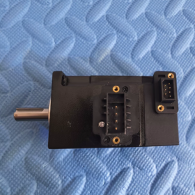
- Connettori: I connettori di alimentazione ed encoder sono disposti lateralmente sul retro del motore. Spazio di riserva nella progettazione delle apparecchiature.
- Avviso di scambio meccanico: Variante dotata di freno T32R lunghezza totale 121,5 mm; non può essere scambiato direttamente senza modificare il telaio meccanico.
- Numeri di parte dei cavi corrispondenti (Approvvigionamento pezzi di ricambio)
Cavo di alimentazione: S6-L-M04-xxx (40-cavo alimentazione telaio)
Cavo encoder per multigiro assoluto a 18 bit: S6-E-T3-xxx
Non direttamente compatibile con i cavi definiti per l'encoder A3.
INNOVAZIONE MS1H4-10B30CB-T331R (40 Telaio, 100W, Nessun freno) Specifiche di installazione complete
- Tipo di montaggio di base
Montaggio standard: Montaggio con flangia anteriore (Flangia IEC B3)
È supportato solo il montaggio su flangia; nessuna struttura con montaggio a piedi. Dimensione flangia quadra 40mm.
Suffisso R = Versione con flangia standard; Albero pieno con chiavetta parallela e filettatura interna sull'estremità dell'albero.
- Specifiche del dispositivo di fissaggio (Critico)
- Fori di montaggio: 2 fori passanti Φ4,5 distribuiti diagonalmente
- Bullone consigliato: Vite a testa cilindrica con esagono incassato M4 (Grado ≥8.8)
- Coppia di serraggio standard: 2.4 N·m
✅Regola di funzionamento: Stringere in diagonale in più passaggi. Evitare il serraggio completo su un lato per evitare la distorsione della flangia.
- Piano di riferimento di montaggio: Superficie flangia anteriore motore; planarità ≤0,02 mm.
- Orientamenti di montaggio consentiti
| Orientamento di montaggio | Ammissibilità | Requisiti obbligatori |
| Montaggio orizzontale (Albero orizzontale) | ✅ Consigliato | Dissipazione ottimale del calore; nessun vincolo aggiuntivo |
| Albero di montaggio verticale verso il basso (Carico sospeso) | ✅ Consentito | Riservare spazio per i connettori dei cavi; Nessun freno di stazionamento – NON sospendere i carichi quando l'alimentazione è disattivata. |
| Albero di montaggio verticale verso l'alto (Caricare rivolto verso l'alto) | ⚠️ Non raccomandato per operazioni a lungo termine | Invecchiamento accelerato del paraolio anteriore; applicabile solo per apparecchiature a ciclo breve. |
| Monte inclinato (Qualsiasi angolo) | ✅ Consentito | Disporre i connettori verso il basso per evitare l'ingresso di acqua di condensa. |
Avviso importante: Nessun freno di stazionamento elettromagnetico installato. Severamente vietato per il sollevamento di carichi verticali. Selezionare il modello dotato di freno T32R per assi verticali!
- Specifiche del collegamento tra albero motore e carico
4.1 Riepilogo dei parametri dell'albero
Diametro albero Φ30 h7; estensione dell'albero 25mm; larghezza chiave parallela 2,5 mm; filettatura interna all'estremità dell'albero.
4.2 Regola di installazione dell'accoppiamento
❌ Non colpire mai direttamente l'estremità dell'albero motore con un martello!
L'impatto danneggerà l'anello magnetico dell'encoder e disabiliterà permanentemente il motore.
✅Pratica corretta: Utilizzare strumenti di montaggio idraulici, montaggio termico (temperatura ≤80℃), o metodo del martinetto a vite per l'accoppiamento a pressione.
4.3 Tolleranza di coassialità
Offset radiale massimo consentito: ≤0,03 mm
Disallineamento angolare massimo: ≤0,5°
Accoppiamento consigliato: Giunto flessibile a ganasce / Accoppiamento a membrana
Un disallineamento eccessivo provoca vibrazioni, usura prematura dei cuscinetti e rumore ad alta velocità.
4.4 Carico esterno consentito continuo
Carico radiale ammissibile all'estremità dell'albero: 120 N
Carico assiale ammissibile all'estremità dell'albero: 40 N
La trasmissione a cinghia e la trasmissione a ingranaggi generano forze radiali continue; il calcolo del carico è obbligatorio per evitare di superare i limiti.
- Dissipazione del calore & Spazio per l'installazione
- Metodo di raffreddamento: Raffreddamento a convezione naturale. Lasciare ≥30 mm di spazio libero attorno alle alette di raffreddamento.
- Non collegare la parte posteriore del motore direttamente alla lamiera o al coperchio chiuso.
- Declassare la potenza del motore quando la temperatura ambiente supera costantemente i 40°C; declassare la potenza in base all'altitudine >1000M.
- Temperatura massima consentita della superficie dell'alloggiamento durante il funzionamento: ≤120°C.
- Connettore & Regole per il percorso dei cavi
- I connettori di alimentazione ed encoder si trovano sul lato posteriore del motore. Riservare spazio per il movimento del cavo nella progettazione meccanica.
- Serracavo per cavi: Installare il serracavo adiacente ai connettori per evitare che la tensione causata dal peso del cavo trascini i connettori.
- Separazione del cablaggio: Cavi di potenza separati e cavi encoder schermati; mantenere una distanza parallela ≥ 30 cm. Incrociare i cavi a 90° ove possibile.
- Impermeabile per connettori: Assicurarsi che le spine siano completamente bloccate. Evitare connettori rivolti verso l'alto all'interno dell'apparecchiatura per evitare l'accumulo di acqua. La classificazione IP67 si applica solo all'alloggiamento del motore; i connettori non sono sigillati IP67.
- Specifiche di messa a terra
- Collegare in modo affidabile il terminale PE dell'alloggiamento del motore alla terra protettiva.
- Gli strati schermanti del cavo di alimentazione e del cavo dell'encoder dovranno essere messi a terra su entrambe le estremità alla barra collettrice di terra dell'armadio secondo lo standard Inovance.
- Resistenza al suolo <100Ω per prevenire la deriva della posizione dell'encoder e gli errori di comunicazione causati da interferenze elettromagnetiche.
- Divieti di installazione (Regole obbligatorie)
- È vietato effettuare saldature o puntature sulla carcassa del motore; l'elevata temperatura distruggerà l'encoder interno.
- È vietata la molatura o la lavorazione della flangia e dell'albero del motore.
- Evitare il funzionamento prolungato in stallo del motore.
- Evitare il lavaggio continuo del paraolio dell'albero con fluido da taglio o contaminazione di olio.
- Non sollevare/spostare il motore afferrandolo per cavi o connettori durante la movimentazione; afferrare solo l'alloggiamento della flangia.
- Procedura di installazione standard
- Base di montaggio pulita, rimuovere bave e trucioli metallici.
- Collegare la flangia del motore alla superficie di montaggio, inserire i bulloni M4 e applicare il pre-serraggio diagonale.
- Fissare temporaneamente il motore e montare il giunto.
- Regolare la posizione del motore e verificare la coassialità con il comparatore.
- Stringere i bulloni alla coppia specificata di 2.4 N·m in sequenza diagonale.
- Installare le staffe per cavi, collegare il cavo di alimentazione e il cavo dell'encoder.
- Verificare la presenza di interferenze meccaniche e rischi di tensione del cavo prima della messa in servizio.





NH42-63-318x560.png "Commutatori automatici di tipo PC CHINT (ATS)NH42-63/4SZ")



