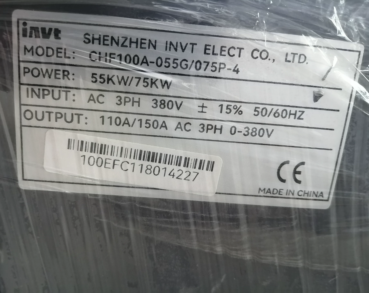
INVT-CHF100A-055G-075P-4 INVT Vector General-Purpose Frequency Converter
- Interpretazione del modello
| Segmento modello | Descrizione |
| INVT | Brand Logo of INVT |
| CHF100A | Series Name: Vector General-Purpose Frequency Converter (enhanced version of the CHF series, integrating the advantages of CHF100 and CHE100) |
| 055G | Suitable for standard motor power of 55kW (G = General Load) |
| 075P | Suitable for heavy-duty motor power of 75kW (P = Heavy Load) |
| 4 | Suitable for three-phase 400V-class voltage (380-415V e) |
- Parametri tecnici fondamentali
- Parametri elettrici di base
| Elemento parametro | Valore | Osservazioni |
| Rated Input Voltage | 380-415V e, three-phase, 50/60Hz | Voltage fluctuation range ±15% |
| Rated Output Power | 55kW (standard load) / 75kW (heavy load) | Rated value for continuous operation |
| Rated Output Current | 105UN (standard) / 135UN (heavy load) | At ambient temperature of 40℃ |
| Output Frequency Range | 0.00-600.00Hz | Accuracy ±0.01Hz |
| Control Mode | Sensorless Vector Control (SVC), V/F Control, Torque Control | Three modes optional |
- Performance Indicators
| Elemento parametro | Valore | Applicable Conditions |
| Starting Torque | 0.5Hz / 150% rated torque | In sensorless vector control mode |
| Speed Regulation Accuracy | 0.2% rated speed | In SVC mode |
| Torque Response Time | <20SM | During dynamic load changes |
| Carrier Frequency | 1.0-15.0kHz | Adjustable according to motor noise and heating |
| Overload Capacity | 150% rated current for 1 minuto, 180% rated current for 10 secondi | For standard load; 120% rated current for 1 minute for heavy load |
- Mechanical and Environmental Parameters
| Elemento parametro | Valore | Standard/Remarks |
| Classe di protezione | IP20 (main unit) | CEI 60529, must be installed in control cabinet |
| Metodo di raffreddamento | Forced Air Cooling | Built-in cooling fan, automatic derating when overheated |
| Operating Temperature | -10℃~+40℃ | For every 1℃ rise above 40℃, rated current decreases by 1%, maximum temperature 50℃ |
| Storage Temperature | -25℃~+65℃ | No condensation, no corrosive gas |
| Metodo di montaggio | Wall-mounted / Cabinet-mounted | Reserved heat dissipation space required (≥100mm top and bottom, ≥50mm left and right) |
III. Caratteristiche funzionali
- Excellent Control Performance: Adopts DSP control system to realize sensorless vector control, effectively suppressing low-frequency oscillation.
- Funzioni di protezione complete: Equipped with multiple protection functions such as overcurrent, sovratensione, sottotensione, overtemperature, phase loss, sovraccarico, ground fault and short circuit.
- Rich Application Functions: Built-in PLC simple programming, multi-speed control (fino a 16 speeds), PID control, frequency swing control, synchronous control, ecc.
- Strong Communication Capability: Standard RS485 interface, supporting Modbus RTU protocol, expandable with PROFIBUS-DP, DeviceNet and other fieldbuses.
- Flexible Input and Output: 15 digital I/O channels (9DI/6DO by default), 2 analog input channels (0-10V/4-20mA), 2 analog output channels.
- Significant Energy-saving Effect: Functions such as Automatic Voltage Regulation (AVR), automatic current limiting, sleep and wake-up, especially suitable for energy-saving transformation of fan and pump loads.
- Application Scope
- Fans and Pumps: Boiler induced draft fans, central air conditioning fans, cooling tower fans, oilfield water injection pumps, oil transfer pumps, chemical process pumps, ecc.
- Industrial Machinery: Air compressors, injection molding machines, extruders, printing machines, packaging machines, textile machinery, CNC machine tool spindle control.
- Building Materials and Metallurgy: Cement rotary kilns, ball mills, belt conveyors, hoists, auxiliary systems of steel rolling equipment.
- Other Fields: Mining machinery, port cranes, pharmaceutical equipment, food processing machinery, sewage treatment equipment.
- Suggerimenti per la selezione
- Carica la corrispondenza del tipo: Select type G for standard loads (tifosi, pumps), and type P for heavy loads (compressori, extruders).
- Motor Power Adaptation: The rated power of the frequency converter should be ≥ the rated power of the motor; it is recommended to select one level higher for heavy-duty applications.
- Environmental Condition Consideration: Derating use or additional protective measures are required for high-temperature, high-altitude and dusty occasions.
- Special Function Requirements: Select models with corresponding interfaces for communication networking; select vector control mode for fast response.
- Accessory Selection: Optional input and output reactors, filters, braking units, operation panels (universal for CHV100 series).
- Risoluzione dei problemi
| Fault Code | Fault Cause | Troubleshooting Method |
| OV | DC bus overvoltage | Check grid voltage, extend deceleration time, install braking unit. |
| UV | DC bus undervoltage | Check grid voltage, shorten acceleration time, check input phase loss. |
| OC | Output overcurrent | Check insulation of motor and cables, reduce load, extend acceleration time. |
| OH | Frequency converter overtemperature | Check cooling fan, clean air duct, reduce ambient temperature. |
| PH | Input phase loss | Check input power supply, tighten wiring terminals, replace damaged fuses. |
| GF | Guasto a terra | Check insulation of motor and cables, eliminate ground fault points. |
VII. Installation and Wiring Key Points
- Before installation, confirm that the power supply voltage matches the rated voltage of the frequency converter, disconnect the power supply and verify no voltage.
- Adopt 35mm DIN rail mounting or wall-mounted mounting to ensure sufficient heat dissipation space.
- Main circuit wiring: R/L1, S/L2, T/L3 are inputs; U, V, W are outputs; PE is the grounding terminal.
- Control circuit wiring: Shielded wires should be used for analog input, with the shielding layer grounded at one end; digital input should avoid routing in the same slot as high-voltage electricity.
- Check parameter settings before power-on, especially basic parameters such as motor rated power, rated current and rated frequency.
 Contattore,interruttore automatico,inverter solare,contatore elettrico,batterie solari


")

NH42-63-318x560.png "Commutatori automatici di tipo PC CHINT (ATS)NH42-63/4SZ")


