 Contattore,interruttore automatico,sensore,Codificatore,PLC,Convertitore

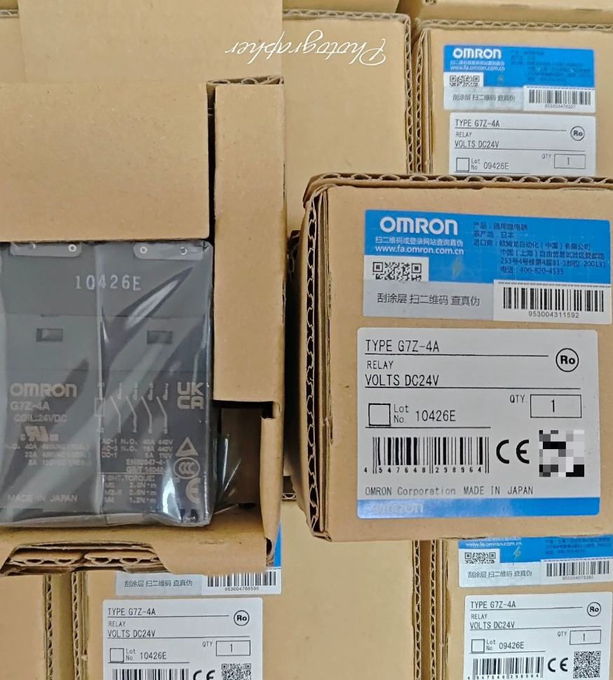

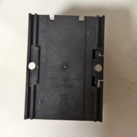
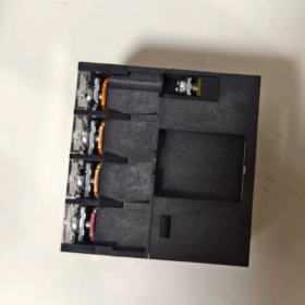
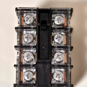
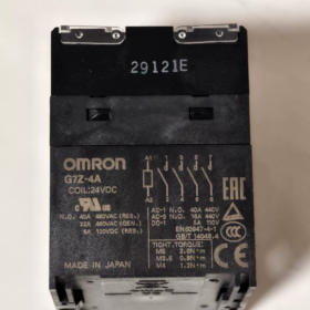
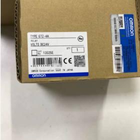
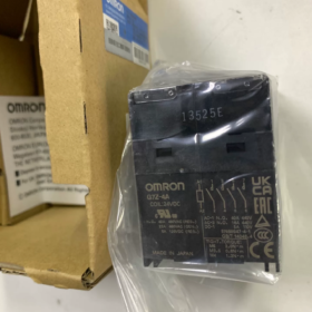
Serie: G7Z Multi-pole Relè di potenza (Compact Electromagnetic Contactor Type)
Definizione del modello:
G7Z: Codice della serie, high-power double-break relay
-4UN: 4-pole Normally-Open (4UN, 4PST-NO), no normally-open main contacts
Complete part numbers: G7Z-4A DC12/ G7Z-4A DC24; suffix -R denotes revised version; -11Z-R indicates fitted with 1a1b auxiliary contact block
Specifiche elettriche principali
Bobina (DC driven)
| Parametro | CC 12 V | DC24V |
| Tensione nominale della bobina | CC 12 V | DC24V |
| Corrente della bobina | 308 mA | 154 mA |
| Resistenza della bobina | 39 OH | 156 OH |
| Operate Voltage | ≤75% della tensione nominale | ≤75% della tensione nominale |
| Tensione di rilascio | ≥10% of rated voltage | ≥10% of rated voltage |
| Maximum Permissible Voltage | 110% | 110% |
| Consumo energetico della bobina | ~3.7 W | ~3.7 W |
Contatti principali (4-polo n, struttura a doppia rottura, Ag-alloy contacts)
Carico resistivo: 40A @ AC440V; massimo. AC480V
Carico induttivo (cosφ=0.3): 22A @ AC440V
Carico CC: 5A @ DC110V
Massimo. Capacità di commutazione: Resistive 17600 VA; Inductive 9680 VA
Terminali: Morsetti a vite; Montaggio: DIN-rail mountable
Dimensioni: 80×100×100 mm; Indicatore luminoso di funzionamento integrato, enclosed housing
Varianti del modello
- G7Z-4A DC12 / DC24: Basic unit, 4 contatti principali NO, nessun contatto ausiliario
- G7Z-4A-11Z-R DC24: Main unit 4a + attached 1a1b auxiliary contact block for status feedback signals
Legacy G7Z-4A-□Z models are discontinued; replace with -R suffixed versions: G7Z-4A-□Z-R
Applicazioni tipiche
Switching high-power 3-phase 380-440 V loads (riscaldatori, power supplies, tifosi)
DIN-rail installation inside control cabinets, alternative to small contactors; direct PLC DC-output drive
⚠️ Nota: Coil power consumption 3.7 W; calculate current margin for PLC output modules. Derate contact current above 40 °C ambient: reduce 0.7 A per 1 °C rise.
Opzioni di sostituzione
- Omron same-series: G7Z-4A-xxZ-R (factory upgraded replacement)
- Contactor alternative: 4-pole small AC contactor (40 A class, Bobina CC)
- Equivalente domestico: 4-pole 40 A DC24 V coil DIN-rail power relay. Verify key specs: double-break, AC440 V rating, terminali a vite, coil power consumption.
Common Troubleshooting Checkpoints
- Verify coil supply voltage ≥75 % rated value; measure coil resistance to detect burnt-out coils
- Main contact erosion: Service life drops sharply under 40 A inductive loads; use derated contactor sizing as preferred practice
- Maintain adequate heat dissipation in high-temperature environments to avoid insufficient current derating.
OMRON G7Z-4A Mounting Instructions
The G7Z-4A supports DIN-rail mounting and panel screw-mounting. Mandatory mounting orientation: coil terminals facing upward. Never mount with terminals upside-down.
- DIN-rail Mounting (Standard for Control Cabinets)
Compatible rail: Standard DIN EN50022, 35×7.5 mm (TR35-15Fe) steel rail
❗ Not compatible with over-thick heavy-duty rails from some manufacturers, risk of insecure latching.
Mount orientation: Horizontal installation with coil terminals upward. Vertical or inverted mounting is prohibited.
Installation procedure: Hook rear spring clip onto upper rail edge, press down until a “click” confirms full engagement.
Anti-vibration securing: Per ambienti ad alte vibrazioni, fit PFP-M rail end stops on both sides to prevent sliding or dislodging.
Rimozione: Pry down bottom spring clip with flat-blade screwdriver and lift the relay upwards.
- Panel Screw-Mounting
Secure via two M4 screws through mounting holes on the housing. Tightening torque strictly 1.2-1.3 N·m. Avoid over-tightening (cracked housing) or under-tightening (scioltezza).
Keep coil terminals oriented upward.
Suitable for custom enclosures without standard DIN rail.
- Blocco contatti ausiliari (G73Z-□Z-R) Assemblea & Rimozione
Auxiliary contact blocks provide status feedback for G7Z-4A base unit:
- Insert block claws into the recesses of the relay main body;
- Press inward until latched with audible click;
- Rimozione: Slide auxiliary block to disengage hooks and claws. Do not pry plastic hooks forcibly.
- Distanza di montaggio & Thermal Requirements (Critical for Current Derating)
- Maintain minimum 5 mm clearance between relay housing and cabinet metal ground surfaces on all sides;
- Multiple G7Z-4A side-by-side: Maintain minimum 30 mm spacing between units. Close adjacent mounting causes excessive self-heating and mandatory contact derating;
- Keep upper area well-ventilated; avoid stacking heat-generating components directly above;
- Derate contact current for ambient temperatures exceeding 40 °C.
- Terminal Tightening Torque
| Terminal Screw | Coppia di serraggio |
| Terminali di alimentazione principali (M5) | 2.0‑2.2 N·m |
| Terminali della bobina (M3.5) | 0.8‑0.9 N·m |
Loose terminals cause overheating and burnout under high load; torque wrench usage is recommended.
- Divieti severi
- ❗ Do NOT mount upside-down (terminali rivolti verso il basso): risk of abnormal mechanical operation and shortened service life.
- ❗ Do NOT mount rotated 90° on side.
- ❗ Do NOT use non-standard over-thick DIN rails.
- ❗ Do NOT touch live terminals while powered; fit terminal safety covers for shock hazard protection.
- Post-installation Checks
- Relay secured firmly without wobble (rail clip or mounting screws fully tightened);
- Auxiliary contact block is securely latched;
- All terminals torqued to specified values;
- Thermal clearances met; no obstructions surrounding the unit.
OMRON G7Z-4A Ambient Temperature Specifications
Temperatura ambiente operativa
-25 °C ~ +60 °C, no icing, nessuna condensa.
40 A rated contact current applies at ambient ≤45 °C.
High-Temperature Current Derating Rule (Critico)
For ambient temperature >45 °C up to 60 °C: reduce continuous allowable current by 0.7 A per 1 °C rise.
Example @50 °C: Max continuous current = 40-(50-45)×0.7 = 36.5 A
Example @60 °C limit: Max continuous current = 40-(60-45)×0.7 = 29.5 A
Same derating applies when G73Z-□Z-R auxiliary contact block is fitted.
Umidità ambientale
5 % ~ 85 % RH, senza condensa.
Temperatura di conservazione (Unpowered unit)
Not explicitly listed on datasheet; industrial practice: -40 °C ~ +70 °C, senza formazione di ghiaccio o condensa.
Design Notes
- Operation at -25 °C is permitted; prevent cabinet condensation; dehumidify cabinet before cold startup.
- Closely-mounted multiple units add self-heating; actual component temperature is higher than cabinet air-sensor reading. Adequate thermal spacing is mandatory.
- Coil resistance increases with temperature. Verify coil supply voltage maintains ≥75 % rated value under high-temperature conditions to prevent unreliable pull-in.
- Do not operate above 60 °C ambient: accelerates contact erosion and coil aging.
OMRON G7Z-4A Contact Configuration
Main unit main contacts: 4UN (4PST-NO), four-pole normally-open; no main normally-closed contacts
Model code explanation: 4A = 4-pole-All-NO. All contacts open when coil de-energized; all four poles close simultaneously upon coil energization.
Contact mechanism: Double-break. Two separate break points per pole, enhanced arc-extinguishing capability for high-voltage AC440 V heavy-load switching.
Materiale di contatto: Ag-alloy.
Main Contact Ratings (per pole)
Carico resistivo: 40 A @ AC440 V
Carico induttivo (cosφ=0.3): 22 A @ AC440 V
Carico CC: 5 A @ DC110 V
Contatti ausiliari (Separate G73Z-□Z-R block required; non integrato)
| Codice suffisso | Auxiliary Contact Form |
| ‑20Z‑R | 2UN (DPST‑NO, 2‑pole NO) |
| ‑11Z‑R | 1a1b (SPST‑NO + SPST‑NC, 1NA+1NC) |
| ‑02Z‑R | 2B (DPST‑NC, 2‑pole NC) |
Auxiliary contacts use single-break construction, max rated current 1 A. For status feedback signals only. NOT suitable for carrying main power loads.
Cross-reference for related series models (for selection reference)
- G7Z-4A:4UN (4-polo n)
- G7Z-3A1B:3a1b (3-pole NO +1-pole NC)
- G7Z-2A2B:2a2b (2-pole NO +2-pole NC)
Design Key Points
- G7Z-4A base unit has no main NC contacts. Select G7Z-3A1B / G7Z-2A2B if main normally-closed contacts are required.
- Double-break design provides high inter-phase withstand voltage; well-suited for switching 3-phase heaters and 3-phase fans.
- Auxiliary blocks are strictly for feedback signals; never use for power-carrying circuits.





NH42-63-318x560.png "Commutatori automatici di tipo PC CHINT (ATS)NH42-63/4SZ")



