 Contattore,interruttore automatico,inverter solare,contatore elettrico,batterie solari

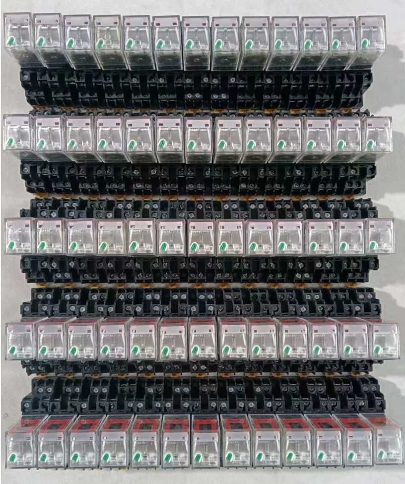

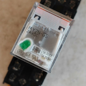
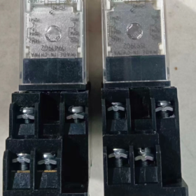
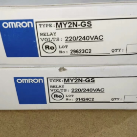
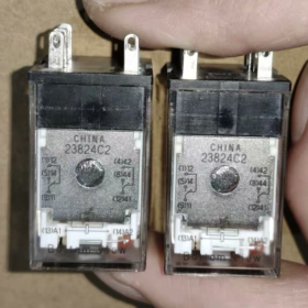
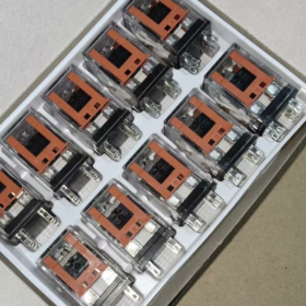
IL OMRON MY2N-GS AC220V is a 2-pole double-throw (DPDT) plug-in miniature intermediate relay from OMRON MY-GS series. It is the official upgraded replacement for the classic legacy model MY2N-J. Standard configurations include an LED operation indicator, mechanical status indicator and manual test locking lever. Adopting silver alloy contacts, è caratterizzato da un'elevata affidabilità, long service life and convenient wiring. Mainly used for PLC output signal amplification, load switching and circuit logic conversion, it is a universal fundamental component for industrial automation control cabinets.
- Scomposizione del codice modello
Full standard model: MY2N-GS AC220/240V
MY: Serie di prodotti, general-purpose miniature power intermediate relay
2: Number of contact sets, 2 sets of changeover contacts (DPDT, 2 Normalmente aperto + 2 Normalmente chiuso)
N: Standard plug-in terminals with built-in operation indicator
GS: Next-generation series (Generation Standard). It replaces the original MY2N-J series, is equipped with an additional locking lever, and delivers optimized contact durability and electrical performance.
AC220/240V: Rated coil voltage, AC 220~240V, compatible with 50/60Hz power supply.
Note supplementari
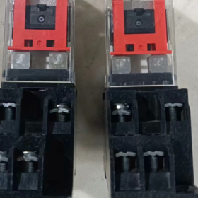
Most products available on the market are fitted with a locking lever by default (suffix -R), supporting manual testing and contact locking.
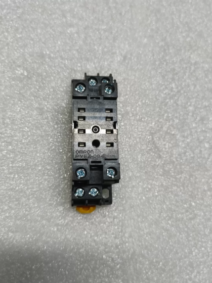
Matched standard 8-pin socket: Screw terminal type PYF08A, push-in terminal type PYF08A-PU.
- Principali Specifiche Tecniche
| Categoria | Specifiche |
| Configurazione dei contatti | 2 sets of changeover contacts (DPDT, 2NO+2NC) |
| Corrente di contatto nominale | 5UN (AC250V resistive load); 5UN (DC30V resistive load) |
| Materiale di contatto | Lega d'argento (AgSnO₂) |
| Tensione nominale della bobina | AC 220~240V, 50/60Hz |
| Consumo energetico della bobina | ca. 1.2~1.5 VA |
| Operate Time | ≤ 20 SM |
| Tempo di rilascio | ≤ 20 SM |
| Vita meccanica | ≥ 50 milioni di operazioni |
| Vita elettrica | ≥ 100,000 operazioni (under rated resistive load) |
| Dielectric Withstand Voltage | 2kV CA / 1min (between coil and contacts) |
| Indicazione dello stato | Red LED indicator (lights up when energized) + Mechanical indicator lever |
| Tipo di montaggio | Tipo plug-in, used with matched standard socket |
| Number of Pins | 8 perni |
| Temperatura ambiente operativa | -40℃ ~ +70 ℃ (Nessuna condensa) |
| Protezione dall'ingresso | IP40 (Relay body) |
| Certificazioni | CE, UL, CSA, VDE, CQC |
- Full Model List of the Same Series
4.1 Classified by Contact Sets
| Contact Sets | Pin Count | Modello standard | Model with Locking Lever | Corrente di contatto nominale |
| 2 contatti di scambio (2NO+2NC) | 8 perni | MY2N-GS | MY2N-GS-R | 5UN |
| 4 contatti di scambio (4NO+4NC) | 14 perni | MY4N-GS | MY4N-GS-R | 5UN |
4.2 Common Coil Voltage Ratings
The entire series supports the following standard voltages, distinguished only by voltage suffix:
DC: CC 12 V, DC24V, DC48V
AC: AC24V, AC110/120V, AC200/220V, AC220/240V
- Pin Assignment & Istruzioni di cablaggio
5.1 Pin Definition (Top view from the wiring side of the socket)
| Perno n. | Funzione | Descrizione |
| 13 (A1) | One end of coil | Connect to AC220V live wire |
| 14 (A2) | The other end of coil | Connect to AC220V neutral wire |
| 9 | Terminale comune 1 (COM1) | Common pin for the 1st contact set |
| 1 | Normalmente chiuso 1 (NC1) | Conducts with Pin 9 when coil is de-energized |
| 5 | Normalmente aperto 1 (NO1) | Conducts with Pin 9 when coil is energized |
| 12 | Terminale comune 2 (COM2) | Common pin for the 2nd contact set |
| 4 | Normalmente chiuso 2 (NC2) | Conducts with Pin 12 when coil is de-energized |
| 8 | Normalmente aperto 2 (NO2) | Conducts with Pin 12 when coil is energized |
5.2 Precauzioni per il cablaggio
- The AC coil has no polarity requirement. A1 and A2 can be connected to live wire and neutral wire arbitrarily.
- Per carichi induttivi (contattori, elettrovalvole), it is recommended to connect a surge suppressor (RC snubber circuit) in parallel to extend contact service life.
- Do not operate beyond the rated current. Use contactors for secondary switching of high-power loads.
- The locking lever can manually close the contacts, which is applied to power-off commissioning and circuit inspection.
- Applicazioni tipiche
Amplify PLC output signals to drive loads such as solenoid valves, contactors and indicator lights
Circuit logic conversion, level matching and signal isolation inside control cabinets
Start-stop control, signal relay and circuit expansion for automated equipment
Secondary circuit control and protection signal transmission in power distribution systems
- General Troubleshooting Matrix
| Fenomeno di guasto | Causa ultima | Step-by-Step Solutions |
| Relay fails to operate and indicator stays off after power-on | 1. Abnormal supply voltage / Broken wiring | 1. Measure voltage between A1 and A2 to confirm normal AC220V supply |
| 2. Burned-out open coil | 2. Testare la resistenza della bobina; replace the relay if an open circuit is detected | |
| 3. Poor contact with socket | 3. Re-insert the relay and clean socket pins | |
| Indicator lights up but contacts have no output | 1. Welded or oxidized contacts with poor conduction | 1. Test contact continuity; replace the relay if contacts are damaged |
| 2. Broken wiring on load side | 2. Check wiring and integrity of the load circuit | |
| 3. Damaged contacts due to overload | 3. Verify load current; select a higher-rated model for overload conditions | |
| Contacts fail to release and stick together after power-off | 1. Contact welding caused by electric arc under heavy current | 1. Replace the relay and install surge suppression components |
| 2. Mechanical jam or failed return spring | 2. Inspect internal mechanism; replace the whole relay if mechanical jam occurs | |
| Abnormal buzzing noise during operation | 1. Incomplete armature attraction due to low voltage | 1. Adjust supply voltage to the rated range |
| 2. Oil or dust on core surface | 2. Sostituire il relè; do not disassemble the core manually | |
| Excessive heating or burnout of coil | 1. Overvoltage power supply | 1. Ensure supply voltage complies with rated value; overvoltage operation is prohibited |
| 2. Long-term high-frequency switching | 2. Reduce switching frequency or adopt solid state relays |
- Reference of Alternative Models
Original brand legacy replacement: MY2N-J AC220V (Fully pin-compatible, without locking lever)
Alternative domestiche: Chint NJX-13FW/2Z AC220V, Delixi CDZ9-52P AC220V
Imported equivalents: Schneider RXM2LB2P7, ABB CR-MX230AC2L, Phoenix Contact REL-MR-230AC/21
Troubleshooting Matrix for OMRON MY2N-GS AC220V 5A Relay
This model features 2 sets of changeover contacts, 8-pin plug-in structure, LED operation indicator and locking lever. Below is the troubleshooting guide sorted by on-site inspection sequence (from simple to complex), covering faults caused by electrical, mechanical and installation issues.
| Fenomeno di guasto | Causa ultima | Step-by-Step Solutions |
| No operation and red LED indicator off after power-on | 1. Fault in external power circuit: No voltage, cablaggio allentato, broken live/neutral wire | 1. Measure AC voltage between socket Pin 13(A1) and Pin 14(A2). Confirm voltage within AC220V±10%. Check upstream switches and terminals if no voltage is detected. |
| 2. Poor socket contact: Oxidized pins or loose connection between relay and socket | 2. Cut off power, pull out the relay, clean oxide on pins and socket terminals, then reinsert firmly. | |
| 3. Burned-out open coil: Overvoltage breakdown, insulation aging or surge impact | 3. Misurare la resistenza della bobina. The normal resistance is approx. 12~15kΩ at 25℃. Replace the relay if open circuit or abnormal resistance occurs. | |
| 4. Locking lever stuck at release position (for -R version) | 4. Reset the top locking lever to normal position to eliminate mechanical jam. | |
| LED lights up but contacts have no output | 1. Wrong wiring for contact circuit: Mixed connection of common, NO and NC terminals | 1. Verify pin definition: COM terminals are Pin 9 and Pin 12; NO terminals are Pin 5 and Pin 8. Ensure no wrong connection to NC pins. |
| 2. Broken load circuit: No power for load or loose terminals | 2. Press the locking lever to manually close contacts and test continuity. If still open, inspect power and wiring on load side. | |
| 3. Burned or oxidized contacts caused by long-term overload and electric arc | 3. Replace the relay if contacts remain open due to burnout or oxidation after manual closing. | |
| 4. Internal mechanism jam: Coil pulls in normally but linkage fails to drive contacts | 4. Replace the relay if mechanical jam is found during manual operation. | |
| Contacts stay closed and cannot release after power-off | 1. Saldatura dei contatti: Caused by overload, short circuit or electric arc without surge suppression for inductive loads | 1. Cut off power and confirm no voltage on coil. Reset locking lever and check if contacts open. |
| 2. Failed return spring: Elasticity attenuation due to frequent switching and high temperature | 2. Replace the relay immediately if contacts are still closed after reset. Welded contacts cannot be repaired for reuse. | |
| 3. Foreign matter jam: Dust or iron chips stuck inside armature or contact mechanism | 3. Ensure load current does not exceed 5A. Install RC surge suppressor for inductive loads. | |
| 4. Accidental lock of locking lever after manual test | 4. Clean surrounding dust and iron chips; replace the relay if mechanical jam cannot be fixed. | |
| Abnormal buzzing noise during operation | 1. Low supply voltage leads to incomplete core attraction and armature vibration | 1. Measure coil voltage and keep it within AC220V±10%. Check voltage drop in power circuit if voltage is low. |
| 2. Olio, dust or rust on core surface resulting in excessive magnetic gap | 2. Reinsert the relay fully and tighten fixing screws of socket and rail. | |
| 3. Broken short-circuit ring on core (unique fault of AC coil) | 3. Replace the relay if noise persists after cleaning core surface (damaged short-circuit ring or worn core). | |
| 4. Loose fit between relay, socket and DIN rail causing resonance | 4. Adjust mounting position to eliminate resonance gap. | |
| Excessive heating or black burnout of coil | 1. Severe overvoltage exceeding upper limit AC240V leading to coil overload | 1. Monitor supply voltage strictly; long-term overvoltage operation is forbidden. |
| 2. Excessively high switching frequency causes cumulative overheating beyond Class B insulation limit | 2. Limit switching frequency ≤ 20 volte al minuto. Use solid state relay for high-frequency working conditions. | |
| 3. Poor heat dissipation under high ambient temperature accelerates insulation aging | 3. Improve heat dissipation inside cabinet. Keep away from heat-generating components such as inverters and contactors. Ambient temperature shall not exceed 70℃. | |
| 4. Insulation breakdown caused by overvoltage and surge | 4. Connect RC surge suppressor in parallel with coil to suppress transient overvoltage during power-off. | |
| Contatto scarso, intermittent signal | 1. Oxidation and dust on contact surface leading to high contact resistance | 1. Cut off power, pull out the relay, clean oxide on contacts and pins, then insert tightly. |
| 2. Too low load current cannot break through oxide layer (low-level signal circuit) | 2. Use gold-plated contact relay or properly increase circuit current for low-level signal applications. | |
| 3. Fatigue or oxidation of socket pins causing loose connection | 3. Replace matched PYF08A socket if pins lose elasticity or are severely oxidized. | |
| 4. Incomplete insertion of relay leading to mechanical intermittent contact | 4. Replace with a new relay if intermittent fault occurs frequently to prevent repeated oxidation. | |
| Abnormal brightness or flickering of indicator | 1. Unstable power supply with large voltage fluctuation | 1. Measure coil voltage and confirm stable power supply without severe fluctuation. |
| 2. Poor socket contact leading to intermittent coil power supply | 2. Reinsert the relay and clean pins to eliminate loose contact. | |
| 3. Aging and failure of current-limiting resistor for indicator | 3. Measure coil resistance if indicator malfunctions under stable voltage. Replace the relay immediately if inter-turn short circuit (bassa resistenza) is detected. | |
| 4. Coil inter-turn short circuit causing abnormal voltage division | 4. Temporary use is allowed if only indicator fails while contacts work normally. Batch replacement is recommended. |
Supplementary Troubleshooting Notes
- Inspection Priority: Follow the sequence: External power supply → Socket contact → Relay body. 80% of faults are caused by wiring and socket problems. Prioritize these checks to avoid unnecessary replacement.
- Norme di sicurezza: Comply with electrical safety standards during live tests. Cut off power before inspecting contacts and coils to prevent electric shock and short circuit.
- Service Life Reference: The rated electrical life is 100,000 operations under resistive load. The service life will decrease by more than 50% per carichi induttivi. Regular replacement is recommended when the service limit is reached.


")


NH42-63-318x560.png "Commutatori automatici di tipo PC CHINT (ATS)NH42-63/4SZ")


