 Contattore,interruttore automatico,sensore,Codificatore,PLC,Convertitore

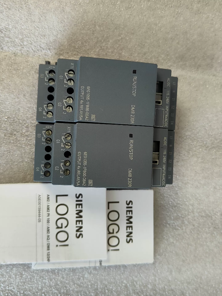

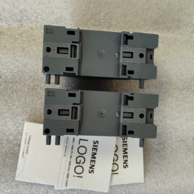
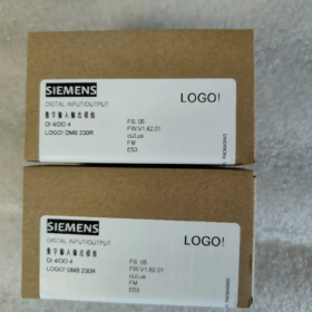
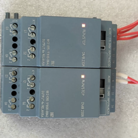
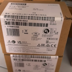
Nome e cognome: LOGO! DM8 230R I/O digitali Modulo di espansione (LOGO! 8 Serie)
- Interpretazione del codice modello
6ED1055-1FB00-0BA2
6ED1055: Prefisso per LOGO! 8 moduli di espansione in serie
1FB: DM8230R, 115/230 Alimentazione AC/DC V, 4Uscita relè DI/4DO
00: Versione dell'hardware
0BA2: Versione del firmware (LOGO!8 piattaforma, incompatibile con LOGO!6/7 (0BA6/0BA7) unità principali)
- Specifiche elettriche principali
| Articolo | Specifica |
| Alimentazione elettrica | 115~230 V CA/CC (85~265 V CA; 100~253 V CC) |
| Ingresso digitale DI | 4 canali, segnale AC/DC universale |
| Logica 0: <40 V CA /< 30 V CC | |
| Logica 1: >79 V CA / >79 V CC | |
| Ritardo di ingresso: 0→1=40ms; 1→0=75ms | |
| Uscita digitale DO | 4 canali relè contatti isolati normalmente aperti |
| Carico resistivo: 5 UN / 250 V e | |
| Carico induttivo: 3 UN / 250 V e | |
| Corrente di carico minima: 100 mA | |
| Frequenza di commutazione massima: 2 Hz (resistivo); 0.5 Hz (induttivo) | |
| Montaggio | 35 Guida DIN da mm, larghezza 2 IL (35.5 mm) |
| Dimensioni complessive | L35,5 × A90 × P58 mm |
| Classe di protezione | IP20 (solo per installazione in armadio) |
| Temperatura ambiente operativa | -20 ℃ ~ +55 ℃, nessuna condensa |
| Peso | ca. 0.17 kg |
- Istruzioni di compatibilità
✅ Unità principali supportate: LOGO! 8 / 8.2 / 8.3 (0BA8 e firmware successivo)
Modelli tipici dell'unità principale: 6ED1052-1FB08-0BA0, 6ED1052-1FB08-0BA1 e altri 230 V unità principali
❌ Non supportato: LOGO! 6, LOGO!7 (0BA6/0BA7) unità principali. Il protocollo del bus backplane è diverso, comunicazione non disponibile
- Definizione del terminale (Superiore: Energia & Ingresso; Metter il fondo a: Produzione)
Terminali Superiori (Alimentazione elettrica + Ingresso)
L1, N: Alimentazione di funzionamento del modulo
I1, I2, I3, I4: 4 ingressi digitali
Terminali inferiori (Uscita relè)
Q1, Q2, Q3, Q4: 4 gruppi di contatti normalmente aperti a relè indipendenti (2 terminali per canale, nessun terminale comune)
⚠️ Importante: Quattro relè sono isolati elettricamente; diversi circuiti di tensione possono essere collegati a ciascun canale in modo indipendente
- Scenari applicativi tipici
Piccolo controllo HVAC, pompa dell'acqua & controllo della ventola, circuiti di illuminazione, interblocco della porta, semplici linee di trasporto. Ideale per siti dotati di impianti esistenti 220 Sensori V AC e circuiti contattori senza alimentazione DC aggiuntiva.
- Linee guida per la selezione & Insidie comuni
- Il segnale di ingresso deve superare 79 V per essere riconosciuto in modo affidabile come logica 1; non è possibile utilizzare segnali a bassa tensione.
- Contatti meccanici del relè non adatti alla commutazione ad alta frequenza. Selezionare i moduli di uscita a transistor per un funzionamento frequente.
- Limite massimo di espansione: Un unico LOGO! l'unità principale può connettersi a 4 moduli di espansione.
- Si consiglia di utilizzare la stessa alimentazione di fase per tutti i canali di ingresso. Non collegare I1~I4 tra fasi diverse per evitare falsi allarmi causati dalla tensione indotta.
- Installare smorzatori RC o diodi di ricircolo in parallelo con carichi induttivi (contattori, elettrovalvole) per prolungare la vita utile del relè.
- Confronto con modelli di serie simili
6ED1055-1FB10-0BA2 (DM16230R): 8Versione relè DI+8DO con capacità I/O raddoppiata
6ED1055-1HB00-0BA2 (DM824R): 24 Versione alimentata in Vcc
Documentazione tecnica completa per Siemens 6ED1055-1FB00-0BA2 (LOGO! DM8230R)
- Informazioni di base sul prodotto
Ordine n.: 6ED1055-1FB00-0BA2
Nome del prodotto: LOGO! Modulo di espansione digitale DM8 230R (LOGO!8 Serie)
Funzione: 4DI / 4Modulo di espansione uscite relè DO
Posizionamento: Estendi la capacità I/O per LOGO!8/8.2/8.3 unità principali, non può essere eseguito in modo autonomo
- Interpretazione completa del codice modello
6ED10551FB000BA2
- 6ED1055: LOGO! 8 categoria del modulo di espansione in serie
- 1FB: DM8230R, 115Alimentazione ~230 V CA/CC, 4-ingresso CA del canale, 4 uscite relè indipendenti normalmente aperte
- 00: Revisione dell'hardware
- 0BA2: Versione del firmware (LOGO!8 piattaforma, incompatibile con LOGO!6/7 (0BA6/0BA7) controllori)
- Specifiche elettriche dettagliate
3.1 Alimentazione elettrica
| Parametro | Specifica |
| Tensione nominale | 115…230 V CA/CC |
| Gamma operativa | AC: 85~265 V; DC: 100~253 V |
| Gamma di frequenza | 47~63 Hz |
| Consumo energetico del modulo | Massimo. 2.2 VA |
3.2 Ingresso digitale DI (I1, I2, I3, I4)
Quantità: 4-ingresso AC/DC universale a canale
Logica 0: <40 V CA / <30 V CC
Logica 1: >79 V CA / >79 V CC
Ritardo della risposta in ingresso: 0→1: 40 SM; 1→0: 75 SM
Tipo di ingresso: Ingresso tensione CA passivo, 24 I segnali V DC non sono ammessi
Lunghezza massima del cavo: 100 M (cavo non schermato)
3.3 Uscita relè DO (Q1~Q4, contatti normalmente aperti isolati)
⚠️ Quattro relè sono reciprocamente isolati; a ciascun canale possono essere collegati circuiti di tensione diversi
|Tipo di carico|Valutazione dei contatti|
| —| —|
|Carico resistivo (Resistori, Illuminazione)|5 UN / 250 V e|
|Carico induttivo (Contattori, Elettrovalvole)|3 UN / 250 V e|
|Corrente di trasporto minima|100 mA (Al di sotto di questo valore potrebbero verificarsi scarse prestazioni di contatto)|
|Frequenza di commutazione massima|Carico resistivo: 2 Hz; Carico induttivo: 0.5 Hz; Limite meccanico a vuoto:10 Hz|
|Operazione vietata|È vietato il collegamento in parallelo di più contatti di uscita per l'aumento di corrente|
- Meccanico & Parametri Ambientali
Montaggio: 35 Guida DIN standard da mm
Larghezza: 2 IL (35.5 mm)
Dimensioni complessive: L35,5 × A90 × P58 mm
Peso: ca. 170 G
Classe di protezione: IP20 (solo per uso in armadietti interni)
Temperatura operativa: -20 ℃ ~ +55 ℃ (vietata la formazione di condensa)
Magazzinaggio & Temperatura di trasporto: -40 ℃ ~ +70 ℃
Umidità relativa: 5% ~ 95%, nessuna condensa
Resistenza alle vibrazioni: Conforme all'IEC 60068-2-6
- Definizione del terminale
Terminali Superiori (Alimentazione elettrica + Ingresso)
L1, N: Alimentazione di funzionamento del modulo 115~230 V CA/CC
I1, I2, I3, I4: 4 ingressi digitali
Terminali inferiori (Uscita relè)
Q1 due terminali: 1primo contatto normalmente aperto del relè
Q2 due terminali: 2e contatto normalmente aperto del relè
Q3 due terminali: 3contatto normalmente aperto del terzo relè
Q4 due terminali: 4contatto normalmente aperto del relè
- Regole di compatibilità del sistema
✅ Unità principali supportate (LOGO!8 Piattaforma)
6ED1052-1FB08-0BA0, 6ED1052-1FB08-0BA1, tutto LOGO!8.2 / 8.3 230 I controllori V
Quantità massima di espansione: Fino a 4 moduli di espansione per LOGO! unità principale
❌ Attrezzatura incompatibile
LOGO!6 (0BA6), LOGO!7 (0BA7) controller legacy. Mancata corrispondenza del protocollo di comunicazione del backplane, non può essere riconosciuto.
- Requisiti di configurazione del software
Software di programmazione: LOGO! Soft Comfort V8.0 o successiva
- Selezionare il modello del modulo di espansione corrispondente nel catalogo hardware del progetto;
- Gli indirizzi I/O dei moduli di espansione seguono automaticamente gli indirizzi dell'unità principale, non è richiesta alcuna assegnazione manuale;
- Verificare l'elenco dell'hardware prima del download del programma per evitare errori causati dalla mancata corrispondenza della versione.
- Certificazioni
CE, UL, CSA, CQC; Conforme alla norma EN 61010-1, IN 55011 (Classe EMC B, applicabile per ambienti di edifici commerciali)
- Linee guida per l'implementazione dell'ingegneria (Specifiche ufficiali)
- Gli smorzatori RC devono essere collegati in parallelo con i carichi induttivi (elettrovalvole, bobine del contattore) per i circuiti CA per prolungare la durata della vita del relè.
- Si consiglia di adottare un'alimentazione dalla stessa fase per tutti i canali di ingresso. Non collegare i terminali di ingresso tra fasi diverse per evitare falsi allarmi indotti dalla tensione vagante.
- I contatti dei relè meccanici hanno una durata operativa limitata. Seleziona i moduli di uscita a transistor (DM824T) per applicazioni start-stop ad alta frequenza.
- Il modulo deve essere installato orizzontalmente; è vietata l'installazione verticale capovolta.
- Mantenere uno spazio libero per la dissipazione del calore negli armadi di controllo per evitare l'accumulo di calore quando più moduli sono montati fianco a fianco.
- Tabella comparativa di modelli simili
| Ordine n. | Modello | Alimentazione elettrica | Configurazione I/O | Tipo di uscita |
| 6ED1055-1FB00-0BA2 | DM8230R | 115~230 V CA/CC | 4DI/4DO | Relè |
| 6ED1055-1FB10-0BA2 | DM16230R | 115~230 V CA/CC | 8DI/8DO | Relè |
| 6ED1055-1HB00-0BA2 | DM824R | 24 A DC | 4DI/4DO | Relè |
Casi applicativi di ingegneria per Siemens 6ED1055-1FB00-0BA2 (LOGO! DM8230R)
Vantaggi fondamentali: Acquisizione diretta di segnali 115~230 V AC/DC; contatti relè isolati pilotano direttamente 220 Carichi V senza alimentazione CC aggiuntiva. Abbinato al LOGO! 230Unità principale RCE (6ED1052-1FB08-0BAx). Adatto per progetti di nuova costruzione e ammodernamento con circuiti di controllo completamente CA in loco.
Allocazione I/O: 4DI (220 Ingresso VCA) + 4 uscite relè indipendenti normalmente aperte
Caso 1: Controllo automatico dell'alternanza della doppia pompa per acque luride per la vasca del seminterrato (Costruire l'approvvigionamento idrico & Drenaggio)
- Requisiti del progetto
Due 220 Pompe per acque luride V per pozzetto di parcheggio sotterraneo; interruttori a galleggiante di livello alto/basso con 220 Segnali di contatto V.
Livello dell'acqua alto: Avviare le pompe; livello altissimo: Le doppie pompe funzionano simultaneamente + udibile & allarme visivo;
Basso livello dell'acqua: Tutte le pompe si fermano;
Alternanza automatica della temporizzazione tra le pompe principale/di riserva per un'usura uniforme; Commutazione manuale/automatica e funzione di feedback dei guasti.
- Configurazione hardware
Unità principale: 6ED1052-1FB08-0BA1 (LOGO! 230RCE, 8DI/4DO a bordo)
Modulo di espansione: 6ED1055-1FB00-0BA2×1 (DM8230R)
- Assegnazione I/O
Canali integrati dell'unità principale
I1: Commutazione automatica/manuale; I2: Pompa ad avvio manuale 1; I3: Pompa ad avvio manuale 2; I4: Arresto di emergenza;
Q1: Contattore della pompa 1; Q2: Contattore della pompa 2;
Canali di espansione del DM8 230R
I5 (Modulo I1): Interruttore a galleggiante di basso livello; I6 (Modulo I2): Interruttore a galleggiante di alto livello; I7 (Modulo I3): Interruttore a galleggiante di altissimo livello; I8 (Modulo I4): Ricambio;
Q5 (Modulo Q1): Cicalino di allarme di livello altissimo; Q6 (Modulo Q2): Spia di guasto; D7, Q8: Ricambio
- Punti salienti della soluzione
Gli interruttori a galleggiante si collegano direttamente al modulo 220 Ingressi V senza relè intermedi. Quattro contatti relè isolati possono pilotare allarmi e spie separatamente con circuiti di alimentazione indipendenti. Non è necessaria alcuna alimentazione aggiuntiva DC24V all'interno del quadro elettrico, semplificando il cablaggio.
Caso 2: Aria fresca & Controllo dell'interblocco della ventola di scarico per edifici adibiti ad uffici (HVAC)
- Requisiti del progetto
Quattro 220 V ventilatori di rinnovo/espulsione con funzionamento programmato, collegamento della temperatura, feedback di funzionamento del ventilatore e allarme di guasto. Gli I/O integrati dell'unità principale sono insufficienti, ampliato con modulo aggiuntivo.
- Elenco dell'hardware
LOGO! 230Unità principale RCE + 6ED1055-1FB00-0BA2×1
- Utilizzo del modulo
DI Channels: 4-contattore del canale che esegue segnali di feedback (220 V);
Canali DO: Contattori di controllo per due ventilatori di scarico aggiuntivi, guasto udibile & allarme visivo, spia di funzionamento del sistema.
- Caratteristiche ingegneristiche
Tutti i segnali di controllo lo sono 220 V e; contatti relè isolati consentono l'alimentazione di fasi diverse. La larghezza compatta 2TE consente di risparmiare spazio sulla guida DIN per piccoli armadi di controllo montati a parete.
Caso 3: Controllo di gruppo temporizzato dell'illuminazione dell'impianto (Sistema di illuminazione dell'edificio)
- Requisiti
Gruppi multipli di 220 Circuiti luminosi a V per impianti di illuminazione stradale e perimetrale; Commutazione graduale basata sul tempo tramite orologio in tempo reale interno; Override manuale locale del pulsante; Feedback sullo stato del guasto.
- Configurazione hardware
LOGO! 230RCE (Orologio in tempo reale integrato) + DM8230R (6ED1055-1FB00-0BA2)
- Assegnazione I/O del modulo
DI: 4-pulsanti manuali locali del canale (220 Segnale V);
FARE: Azionare le bobine del contattore CA per 4 gruppi di illuminazione.
- Motivo della selezione
Il relè del modulo supporta il massimo 5 Un carico resistivo, in grado di pilotare direttamente piccoli contattori. I circuiti di illuminazione sono elettricamente isolati; il guasto di un singolo circuito non influirà sugli altri.
Caso 4: Semplice interruttore di trasferimento automatico per la doppia alimentazione di piccole stazioni di pompaggio
- Requisiti del processo
Due 220 Fonti di alimentazione con controllo V (principale + stand-by). Passa automaticamente all'alimentazione di standby in caso di interruzione dell'alimentazione principale; interblocco per impedire il funzionamento in parallelo; indicazione di stato e allarme di guasto disponibili.
- Configurazione hardware
LOGO! 230Unità principale RC + 6ED1055-1FB00-0BA2
- Assegnazione I/O
Espansione DI: Segnali di feedback per il rilevamento della tensione di alimentazione doppi;
Espansione DO: Controllo delle bobine di chiusura di due interruttori automatici e indicatore di completamento della commutazione.
Questa configurazione è ampiamente adottata nei progetti di ristrutturazione della distribuzione elettrica ed elencata come applicazione tipica ufficiale da Siemens.
Caso 5: Ventola di raffreddamento evaporativo per serra & Controllo dell'interblocco dell'elettrovalvola di spruzzatura (Automazione agricola)
Requisiti
Attiva automaticamente le ventole di raffreddamento e spruzza le elettrovalvole quando la temperatura & l'umidità supera la soglia; ritardare lo spegnimento; pulsanti manuali locali e feedback dei guasti dell'apparecchiatura.
Hardware
LOGO! 230RCE + DM8230R
Espansione DI: Pulsanti manuali, feedback di guasto del relè termico dei ventilatori;
Espansione DO: 220 Elettrovalvola spray V, contattore del ventilatore di standby.
Avviso
Le elettrovalvole appartengono ai carichi induttivi. Installare smorzatori AC RC in parallelo con le uscite relè per prolungare la durata operativa dei relè.
Caso 6: Cancello di sicurezza, Interblocco del trasportatore e della spia per apparecchiature di trasporto leggere (Macchinari OEM)
Logica di controllo
Il trasportatore può avviarsi solo quando il cancello di sicurezza è chiuso; il trasportatore si ferma immediatamente una volta aperto il cancello; la spia rimane accesa e il cicalino suona in modo intermittente durante il funzionamento; l'arresto di emergenza ha la massima priorità.
Configurazione hardware
LOGO! La capacità I/O dell'unità principale è insufficiente, ampliato tramite 6ED1055-1FB00-0BA2:
DI: Finecorsa porta di sicurezza, arresto di emergenza, pulsante di ripristino;
FARE: Contattore del trasportatore, udibile & allarme visivo.
Specifiche tecniche obbligatorie generali per tutti i casi
- ✅ Regola di cablaggio in ingresso: Tutto 4 I canali DI devono essere alimentati dalla stessa fase L + N. Non collegare I1~I4 tra diverse fasi sotto tensione per evitare falsi allarmi causati dalla tensione indotta.
- ✅ Le uscite relè sono contatti normalmente aperti isolati; a ciascun canale possono essere collegati circuiti di tensione diversi.
- ✅ I componenti smorzatori sono obbligatori per i carichi induttivi (contattori, elettrovalvole).
- ✅Massimo 4 i moduli di espansione possono essere collegati in cascata con un LOGO! unità principale.
- ✅ Compatibile solo con LOGO!8 / 8.2 / 8.3 unità principali (0Firmware BA8). LOGO!7 e le versioni precedenti non sono supportate.
- ✅ Non può operare in modo indipendente; devono essere impilati sul lato destro del LOGO! unità principale tramite bus di espansione.





NH42-63-318x560.png "Commutatori automatici di tipo PC CHINT (ATS)NH42-63/4SZ")



