 Contattore,interruttore automatico,sensore,Codificatore,PLC,Convertitore

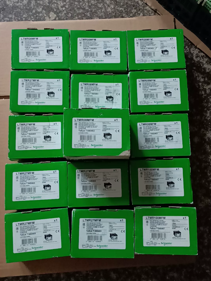

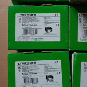
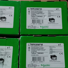
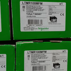
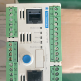
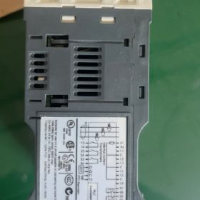
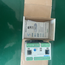
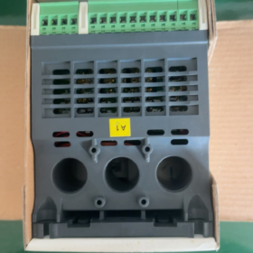
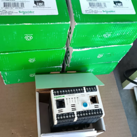
Campi di applicazione di Schneider LTMR27MFM (TeSys T)
Valutazione attuale: 1.35~Controller di gestione intelligente 27A per motori asincroni trifase, dotato di comunicazione Modbus-RTU. Ampiamente utilizzato all'interno degli armadi MCC per la protezione integrata del motore, monitoraggio della corrente e trasmissione remota dei dati.
Scomposizione del codice modello
LTMR27MFM
LTMR: TeSys T controller di gestione del motore unità base
27: Intervallo di misurazione corrente 1,35~27 A (trasformatori di corrente integrati)
M: Interfaccia di comunicazione → Modbus RS485
FM: Alimentazione di controllo 100~240 VCA (AC)
Riferimento incrociato all'interno della serie: LTMR27EFM = Ethernet; LTMR27CFM = CANopen
- Principali Specifiche Elettriche
| Articolo | Parametro |
| Intervallo di corrente del motore | 1.35 … 27 UN (TA incorporato, non è richiesto alcun trasformatore di corrente esterno) |
| Alimentazione del controllore | 100~240 V CA 50/60 Hz (ampia tolleranza: 93.5~264 V) |
| Comunicazione | ModBus RTU RS485, morsettiera + Doppia porta RJ45; indirizzo 1~247; velocità di trasmissione 1,2k~19,2k |
| I/O digitali | 6 ingressi digitali; 3 NESSUNA uscita relè + 1 relè di guasto (1NA+1NC) |
| Portata dei contatti del relè | 5A/250 VCA; 5A/30 VCC |
| Montaggio | Montaggio su guida DIN |
| Dimensioni complessive | L91 mm × A 61 mm × P 122,5 mm; Peso netto 0.53 kg |
| Temperatura operativa | -20 ℃ ~ +60 ℃; Temperatura di conservazione -40~80 ℃ |
| Classe di protezione | IP20 (per installazione interna all'armadio) |
- Funzioni di protezione integrate
✅ Protezione da sovraccarico termico (modello termico)
✅Perdita di fase & 3-protezione dallo squilibrio della corrente di fase
✅ Protezione del rotore bloccato, protezione da avviamento prolungato
✅ Protezione dal sottocarico (monitoraggio della marcia a secco/rottura del nastro)
✅ Protezione dai guasti a terra (TA a sequenza zero interno o esterno)
✅ Supporto per ingresso termistore motore PTC
✅ Registrazione dei guasti, cronologia del viaggio, contatore delle ore di funzionamento
- Capacità di misurazione (Voltaggio & misurazione della potenza con modulo di estensione LTME)
Misurazione dell'unità base: 3-corrente di fase, corrente media, corrente di squilibrio, corrente di guasto a terra;
Se dotato di modulo di estensione LTME: tensione trifase aggiuntiva, potenza attiva/reattiva, fattore di potenza, misurazione dell'energia.
- Software di messa in servizio
Configurazione tramite software SoMove (TeSys T DTM). Collegare il PC direttamente tramite la porta HMI RJ45 anteriore per l'impostazione dei parametri, lettura dei guasti e monitoraggio in tempo reale.
Pannello di visualizzazione locale opzionale: LTMCU / LTMCUF.
- Avviso sul ciclo di vita
La serie completa LTMR TeSys T è in fase di eliminazione (EOL).
Data limite ufficiale per gli ordini: 30 Settembre 2026; Il supporto tecnico termina: 31 Gen 2027
Sostituzione di nuova generazione: TeSys Tera
Unità principale: LTMTMFM (ModBus, 100~240 VCA/CC)
Abbina il sensore di corrente:
2.5~25A → LTMTCTV25UT (corrispondenza più vicina all'applicazione originale da 1,35 ~ 27 A)
⚠️ Il layout del cablaggio e la mappatura dei registri Modbus non sono completamente compatibili tra la vecchia e la nuova serie. Il retrofit in loco richiede la rimessa in servizio del programma.
- Applicazione tipica
Centri di controllo motori MCC, pompe dell'acqua, tifosi, compressori, trasportatori; progetti nel trattamento delle acque, HVAC, industrie metallurgiche e del cemento.
- Distinzione rapida di modelli simili
LTMR27MFM:1.35~27A, ModBus, 100~240 VCA
LTMR100MFM:5~100A, ModBus, 100~240 VCA
LTMR27EFM:1.35~27A, Ethernet/IP
Principali segmenti del settore
- Approvvigionamento idrico comunale & Trattamento delle acque reflue (Applicazione più comune)
✅ Impianti municipali delle acque reflue, acquedotto, stazioni di pompaggio
✅ Carichi tipici: pompe sommergibili, pompe centrifughe, pompe di recupero fanghi, ventilatori di aerazione, raschiatori
Requisiti chiave soddisfatti: protezione da sottocarico (prevenzione del funzionamento a secco), protezione dai guasti a terra, allarme di guasto remoto, monitoraggio energetico.
- HVAC, Edifici commerciali & Costruzione di sistemi elettromeccanici
✅Centri commerciali, ospedali, centri dati, impianti di refrigerazione di parchi industriali
✅ Carichi tipici: pompe per acqua refrigerata, pompe dell'acqua di raffreddamento, ventilatori delle torri di raffreddamento, ventilatori di scarico, Tifosi dell'AHU
Vantaggio: sovraccarico termico & protezione del rotore bloccato; Collegamento Modbus al sistema BA dell'edificio per dati attuali e segnali di guasto.
- Cemento, Materiali da costruzione & Linee di produzione mineraria aggregata
✅ Trasportatori a nastro, elevatori a tazze, azionamenti ausiliari per presse a rulli, ventilatori per l'estrazione delle polveri, attrezzature per lo scarico dei silos
✅ Protezione mirata: protezione del rotore bloccato, protezione da avviamento prolungato, protezione dallo squilibrio di fase per evitare la bruciatura del motore causata da inceppamenti meccanici.
- Chimico & Industria farmaceutica
✅Pompe di circolazione, motori agitatori, motori di compressori d'aria ausiliari, ventilatori per la polvere
✅ Supporta il collegamento del termistore PTC per il monitoraggio della temperatura dell'avvolgimento del motore; intervento rapido in caso di perdita di fase e guasti a terra per soddisfare gli standard di sicurezza industriale.
- Cibo & Bevanda, Linee di produzione di imballaggi
✅ Motori trasportatori, soffiatori, pompe di lavaggio, azionamenti di macchine confezionatrici
Monitoraggio accurato del sottocarico per rilevare carenza di materiale o distacco della cinghia; la cronologia dei guasti facilita la manutenzione della produzione.
- Transito ferroviario & Sistemi Elettromeccanici per Gallerie
✅ Ventilatori a getto tunnel, pompe di drenaggio, aspiratori fumi
Protezione affidabile per i motori dei vigili del fuoco; caricamento dei dati nel sistema di controllo PLC del tunnel.
- Attrezzature ausiliarie della centrale elettrica
✅Pompe di circolazione dell'acqua, ventilatori, trasportatori per la movimentazione delle ceneri; componente standard all'interno delle sale MCC della centrale elettrica.
- Porta & Magazzino logistico
✅ Trasportatori, azionamenti ausiliari dell'impilatore, ventilatori per l'estrazione delle polveri, pompe dell'olio della stazione idraulica
Riferimento di potenza del motore corrispondente (380Motori trifase V)
Campo di misura LTMR27MFM 1,35~27A
Gamma di potenza del motore adatta: 0.75Motore asincrono trifase kW~13kW.
Scenari applicativi non consigliati
- Motori superiori a 13kW (selezionare invece la serie LTMR100)
- Attrezzatura con frequente rotazione avanti/indietro e funzionamento a impulsi pesanti (i parametri del modello termico richiedono una valutazione speciale)
- Involucri antideflagranti senza sufficiente dissipazione del calore (la temperatura ambiente deve rimanere ≤60℃)
Vantaggi della selezione adeguati alle condizioni operative
Trasformatori di corrente integrati, non è richiesta alcuna TC esterna, semplifica il cablaggio dell'armadio;
Interfaccia RS485 modbus, connessione perfetta con Schneider PLC (Modicon M241/M251/M340 ecc.);
Suite di protezione completa: sovraccarico, rotore bloccato, perdita di fase, squilibrio attuale, sottocarico, guasto a terra, Monitoraggio della temperatura PTC;
Registrazione della cronologia dei guasti & statistiche sulle ore di funzionamento, conformi ai progetti di fabbrica intelligente e di gestione dell’energia.
Principio di funzionamento della protezione del rotore bloccato su Schneider TeSys T LTMR27MFM
L'LTMR27MFM implementa la protezione del rotore bloccato tramite campionamento della corrente trifase in tempo reale + giudizio sulla soglia temporale, suddiviso in due modalità configurabili indipendenti: Protezione del rotore bloccato durante l'avvio e protezione del rotore bloccato in stato di funzionamento.
- Fondazione hardware
L'LTMR27MFM integra trasformatori di corrente trifase integrati per campionare continuamente la corrente dello statore ad alta velocità. L'MCU interno calcola in tempo reale:
- Valore efficace delle correnti trifase
- Rapporto tra corrente istantanea e corrente nominale di funzionamento
- Durata della condizione di superamento del limite
Non sono necessari sensori esterni aggiuntivi; la diagnosi si basa esclusivamente sull'analisi della firma corrente.
- Due modalità di protezione del rotore bloccato (Configurato in modo indipendente in SoMove)
Modalità 1: Protezione del rotore bloccato durante l'avviamento del motore
Scenario applicativo: Il motore non può accelerare a causa di un blocco meccanico all'avvio
- Finestra del giudizio: Il controller identifica la sequenza di avvio (impennata di corrente, motore fermo prima dell'accelerazione)
- Logica:
If start-up current > Locked Rotor Start Threshold, and duration ≥ Locked Rotor Start Delay → Trip command triggered
- Adjustable parameters (Quindi Muoviti):
Locked rotor start current: typical range 1.5~8× motor rated current Ie (default 5Ie)
Locked rotor start delay: typical range 0.5~10 s
Scopo: Prevent winding burnout caused by prolonged high current when motor is blocked on startup; distinguish permanent stall from normal short-duration starting inrush current.
Modalità 2: Locked Rotor Protection during Steady-State Operation
Scenario applicativo: Mechanical blockage occurs after motor reaches rated speed (belt jamming, pump impeller stuck, foreign object entrapment)
- Finestra del giudizio: Controller confirms motor completes acceleration and enters stable operation
- Logica:
If operating current > Running Locked Rotor Threshold, e durata ≥ Ritardo rotore bloccato in marcia → Comando di sgancio attivato
- Caratteristiche dei parametri:
La soglia di funzionamento del rotore bloccato è generalmente impostata su un valore inferiore alla soglia di avvio (tipicamente 1,8~4 Cioè), con ritardo più breve per un rapido isolamento dei guasti.
- Flusso di lavoro decisionale interno completo
- LTMR campiona continuamente le correnti trifase e monitora gli andamenti delle variazioni di corrente;
- Distingue automaticamente tre stati operativi: Arresto → Avvio → Marcia costante;
- Attiva le regole di soglia del rotore bloccato corrispondenti in base allo stato operativo;
- Inizia il cronometraggio quando la corrente supera continuamente la soglia impostata;
- Quando la temporizzazione raggiunge il ritardo configurato:
✅Sequenza di protezione interna attivata;
✅ Il contatto del relè di guasto cambia stato;
✅ Disconnette il circuito di controllo del contattore;
✅ Memorizza il codice di errore BLR (Rotore bloccato) localmente;
✅ Carica le informazioni sui guasti del rotore bloccato sul PLC di livello superiore tramite Modbus.
⚠️ Distinzione critica: Protezione del rotore bloccato ≠ Protezione da sovraccarico termico
Protezione da sovraccarico termico: Basato sul modello di accumulo termico del motore, viaggi per sovraccarico lieve e prolungato; caratteristica di risposta lenta.
Protezione del rotore bloccato: Protezione temporizzata ad azione rapida contro gravi sovracorrenti istantanee causate da stallo meccanico, compensare la lentezza della risposta della protezione termica.
- Linee guida chiave per la messa in servizio
- La corrente nominale del motore Ie deve essere inserita con precisione
Tutte le soglie del rotore bloccato vengono calcolate come multipli di Ie. Un'impostazione errata porta al guasto della protezione.
- Principi di ottimizzazione per il ritardo
Tifosi & pompe centrifughe: Tempo di avvio naturale più lungo → prolunga il ritardo di avvio del rotore bloccato per evitare interventi fastidiosi.
Trasportatori & frantoi: Elevato rischio di inceppamento meccanico → minimizza il ritardo del rotore bloccato in funzione per una protezione rapida.
- Coordinamento della protezione
La protezione del rotore bloccato può essere abilitata insieme alla perdita di fase, sbilanciare, protezione da sottocarico e temperatura PTC per la sicurezza multistrato.
- Errore di impostazione comune
Non impostare la soglia del rotore bloccato su un valore superiore alla corrente di spunto di avviamento effettiva del motore; in caso contrario la protezione non risponderà durante l'avvio bloccato.
- Identificazione del guasto dopo lo sgancio
Con pannello display locale LTMCU: Codice errore BLR visualizzato sullo schermo
Registro errori SoMove: Registrato come rotore bloccato
Bit di registro errori Modbus dedicato corrispondente per allarmi HMI/PLC.
- Limitazioni funzionali
La protezione del rotore bloccato si basa esclusivamente sulla firma della corrente dello statore. Rara limitazione dei casi limite:
Se si verifica un inceppamento meccanico con carico leggero e la corrente non supera la soglia, non è possibile rilevare lo stallo. Per tali condizioni, implementare un monitoraggio ridondante tramite protezione da sottocarico o sensori di vibrazione.





NH42-63-318x560.png "Commutatori automatici di tipo PC CHINT (ATS)NH42-63/4SZ")



