 Contattore,interruttore automatico,inverter solare,contatore elettrico,batterie solari

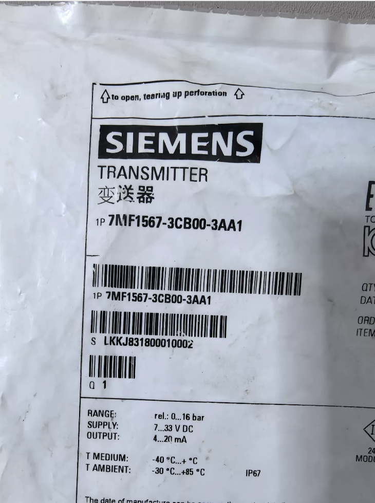

7MF1567: Serie SITRANS P220, struttura interamente saldata in acciaio inox, dedicato al servizio ad alta pressione e refrigerante, trasmettitore di pressione relativa piezoresistivo
3CB00:
Campo di misura: 0 … 16 sbarra (gauge)
Overpressure limit: 40 sbarra
Burst pressure: ca. 80 sbarra
3AA1:
Produzione: 4–20 mA 2-wire system
Connessione al processo: 1/2″-14 NPT internal thread (widely used in North America, different from G1/2″ external thread of 1AA1)
Collegamento elettrico: M16 connector (DIN EN 175301-803-A)
Explosion protection: Non-explosion-proof (tipo standard)
- Parametri tecnici fondamentali (2026 Manuale ufficiale)
- Misurazione & Prestazione
Measured variable: Gauge pressure
Campo di misura: 0–16bar
Precisione: ±0.25% FS (tipico), massimo. ±0,5% FS
Non linearità: ≤0.25% FS
Ripetibilità: ≤0.1% FS
Tempo di risposta: <5 SM (T99)
Long-term stability: 0.25% FS per year
- Specifiche elettriche
Output signal: 4–20 mA 2-wire
Alimentazione elettrica: DC 7–33 V (24 Consigliato VCC)
Capacità di carico: R ≤ (U-10 V) / 0.02 UN
Massimo. load resistance at 24 V: ca. 700 OH
- Intervallo di temperatura
Medium temperature: -30 … +120 ℃
Temperatura ambiente: -25 … +85 ℃
Temperatura di conservazione: -40 … +100 ℃
- Struttura meccanica & Materiale
Wetted & non-wetted parts: Completamente in acciaio inossidabile (1.4435/316l), gasket-free fully welded design, ideal for high pressure and refrigerant media
Connessione al processo: 1/2″-14 NPT internal thread
Collegamento elettrico: M16 connector, IP65 protection grade
Peso: ca. 0.2 kg
Origine: Svizzera (CH)
III. Istruzioni di cablaggio (M16 Connector, 4–20 mA 2-wire)
Pin definition (Standard EN 175301-803-A):
Spillo 1 (+): 24 VDC positive
Spillo 2 (-): 4–20 mA signal return (connect to PLC AI positive terminal)
Spillo 3: Ricambio
PE: Earth connection (housing grounding)
Note sul cablaggio:
2-wire design: Power positive shares line with signal negative
Shielded cable single-ended grounding (control cabinet side only)
Recommended cable: 0.5–1.5 mm² shielded twisted pair cable
- Installazione & Linee guida operative
- Installation position: Vertical or horizontal mounting available; keep away from severe vibration
- Sealing treatment: Use PTFE tape or matched sealant for NPT thread connection
- Zero point calibration:
Output shall be 4.00 mA under zero pressure condition
Adjust zero trim screw at connector side if necessary
- Applicable media:
✅ Gas, liquido, steam, refrigerants (R134a, R410A etc.)
✅ Slightly corrosive media (compatible with stainless steel)
❌ Strong corrosive fluid (concentrated acid, strong alkali), high abrasion slurry
- Common Alternative & Similar Models (Allineare & Connection Comparison)
| Model No. | Allineare (sbarra) | Connessione al processo |
| 7MF1567-3CA00-3AA1 | 0–10 | 1/2″ NPT Internal |
| 7MF1567-3CB00-3AA1 | 0–16 | 1/2″ NPT Internal |
| 7MF1567-3CD00-3AA1 | 0–25 | 1/2″ NPT Internal |
| 7MF1567-3CE00-3AA1 | 0–40 | 1/2″ NPT Internal |
| 7MF1567-3CB00-1AA1 | 0–16 | G1/2″ Esterno (BSP) |
- Risoluzione dei problemi comuni
- Fisso 4 mA output
Alimentazione anomala (sotto 7 V)
Open circuit in signal loop
- Fisso 20 mA output
Over-range pressure (superare 16 sbarra)
Diaphragm damage
- Signal drift & unstable reading
Messa a terra scarsa o interferenze elettromagnetiche
Forte fluttuazione della temperatura
Excessive installation stress
VII. Informazioni sull'ordine & Tempi di consegna (2026 Riferimento)
Production status: Active in production
Standard delivery time: 1 working day (European warehouse)
Prezzo di riferimento: About CNY 700–900 (tasse incluse, 1-5 pz)
Difetti comuni, Causes and Quick Solutions for Siemens 7MF1567-3CB00-3AA1 (P220) Pressure Transmitter
- Nessuna uscita, zero current (0mA)
- Insufficient supply voltage
Causa: Voltage lower than 7VDC, large line voltage drop
Soluzione: Misurare la tensione del terminale, keep stable at 20~26VDC
- Reverse positive and negative wiring
2-wire system rarely burns out device but causes no signal
Soluzione: Swap wiring of pin 1 e perno 2
- Broken cable or loose terminal connection
Soluzione: Conduct continuity test and fasten M16 connector
- Internal circuit damage of transmitter
Fenomeno: No response after power-on, invalid after power replacement
- Constant 4mA minimum output without change
- Actual pressure is zero under normal static status
- Blocked pressure tapping pipeline
Medium crystallization, oil dirt and impurities block pressure inlet
Soluzione: Purge and dredge pressure guiding pipe
- Diaphragm stuck by foreign objects
- Wrong measuring range or mismatched PLC configuration range
- Severe zero drift
Soluzione: Trim zero point on site under zero pressure
- Constant 20mA full-scale output
- Actual pressure far exceeds 16 bar full range
Soluzione: Reduce pressure and verify field actual pressure
- Pressure trapped inside pipeline unable to release
- Pressure diaphragm breakdown and failure
Most frequent hardware fault, è necessaria la sostituzione
- Short circuit of signal wire
Positive and negative wire short circuit leads to full current output directly
- Fluctuating and unstable signal reading
- Excessive on-site vibration (installed near pumps and fans)
Soluzione: Install shock-absorbing bracket and keep away from vibration sources
- Severe electromagnetic interference
Power cables laid together with signal cables without shielding
Soluzione: Single-end grounding for shielded twisted pair, separate wiring layout
- Pulsating medium pressure itself
Soluzione: Install damper and pressure stabilizing buffer tank
- Temperature drift caused by drastic ambient temperature change
- Cablaggio allentato, water ingress and oxidation inside connector
- Large measurement deviation, inaccurate reading, high or low indication
- Uncalibrated zero point (drift after long-term operation)
Soluzione: Calibrate zero under zero pressure to recover accuracy
- Static pressure error caused by improper installation position
- Exceed 120℃ medium temperature damages measurement precision
- Sopra 40 bar overload pressure causes permanent offset
- Inconsistent range setting between PLC program and actual transmitter range
- Fault caused by water ingress and dampness
- Poor sealing of M16 connector leads to water penetration
Fenomeno: Random reading fluctuation, intermittent normal operation
Soluzione: Dry internal parts, replace waterproof connector and reapply sealing glue
- Rainwater and condensed water penetrate into internal structure for outdoor installation
- Overload resistance fault
Fenomeno: Normal supply voltage but current output insufficient
Causa: Excessive internal resistance of rear PLC module exceeding 700Ω load limit
Soluzione: Shorten signal cable length and reduce loop resistance
- Typical Vulnerable Defects Exclusive to P220 Series
- Excessive force during NPT thread installation squeezes internal diaphragm and causes permanent scrappage
- Zero drift easily occurs after long-term operation with refrigerant and low-temperature media
- Failure rate doubles under high-frequency vibration environment
- Fully welded structure disables disassembly and maintenance, direct replacement needed once damaged
- Three-step Quick Self-check Method
- Cut off power supply, stand by for 3 minutes then re-energize
- Release all pressure to check if output returns to 4mA
- Apply standard pressure to verify linear output up to 20mA
Conclusione fondamentale
7MF1567-3CB00-3AA1 (P220) adopts factory integrated fully welded sealing structure. The diaphragm cannot be replaced separately on site. The whole transmitter must be replaced once diaphragm is damaged.
Reasons for Non-separable Diaphragm Replacement (Core Structure of P220)
Model feature: 7MF1567 is fully welded SITRANS P220 transmitter without sealing gasket or detachable pressure cover
Diaphragm structure: 316L/1.4435 diaphragm is directly welded on pressure cavity; pressure cavity and electronic chamber are integrated via laser welding or argon arc welding with no detachable bolts or clamps
Official specification: The transmitter is maintenance-free. Repair work is only available by Siemens authorized personnel and on-site disassembly is prohibited.
Typical Phenomena of Damaged Diaphragm
Fixed 20mA output (over-range or diaphragm breakdown)
Extreme zero drift unable to be calibrated
Medium leakage at thread root or housing joint
Random data fluctuation and internal corrosion caused by water ingress via M16 connector
On-site Replacement Solutions
Soluzione 1: Direct overall replacement (Raccomandato)
Spare part model: 7MF1567-3CB00-3AA1 (same range & connessione)
Replacement steps:
- Cut off power, release pressure and close pressure valve
- Remove M16 connector
- Unscrew 1/2″ NPT thread gently with spanner (avoid squeezing new diaphragm)
- Wrap PTFE tape on new thread, tighten manually then turn 1/4 circle with spanner
- Complete wiring, power on and perform zero calibration
Soluzione 2: Factory return maintenance (High cost & long cycle)
Maintenance content: Replace full welded pressure module and recalibrate
Maintenance cost: Di 60-80% of new product price, delivery cycle 2-4 settimane
Not cost-effective compared with direct replacement
Risks of Forced Disassembly
- Welded cavity cannot be opened without damage, resulting in housing deformation and diaphragm scrap
- Ultra-thin diaphragm (0.1-0.2mm) is easy to crack under prying, knocking and extrusion
- Siemens does not sell separate P220 diaphragm or pressure module, only complete transmitters available
- Disassembly will invalidate IP65 protection and explosion-proof certification, bringing potential safety hazards
Preventive Measures for Diaphragm Damage
- Strictly control installation torque for NPT thread, forbid excessive tightening
- Keep working pressure within 16 bar rated range, avoid instantaneous high pressure impact
- Install shock absorber when mounting near pumps and compressors to prevent fatigue crack of diaphragm
- Limit medium temperature below 120℃ to avoid metal creep and zero drift
- Apply sealing glue on M16 connector for reliable waterproof performance


 8-Strato industriale portuale 2 Centro")


")
NH42-63-318x560.png "Commutatori automatici di tipo PC CHINT (ATS)NH42-63/4SZ")


