 Contattore,interruttore automatico,sensore,Codificatore,PLC,Convertitore

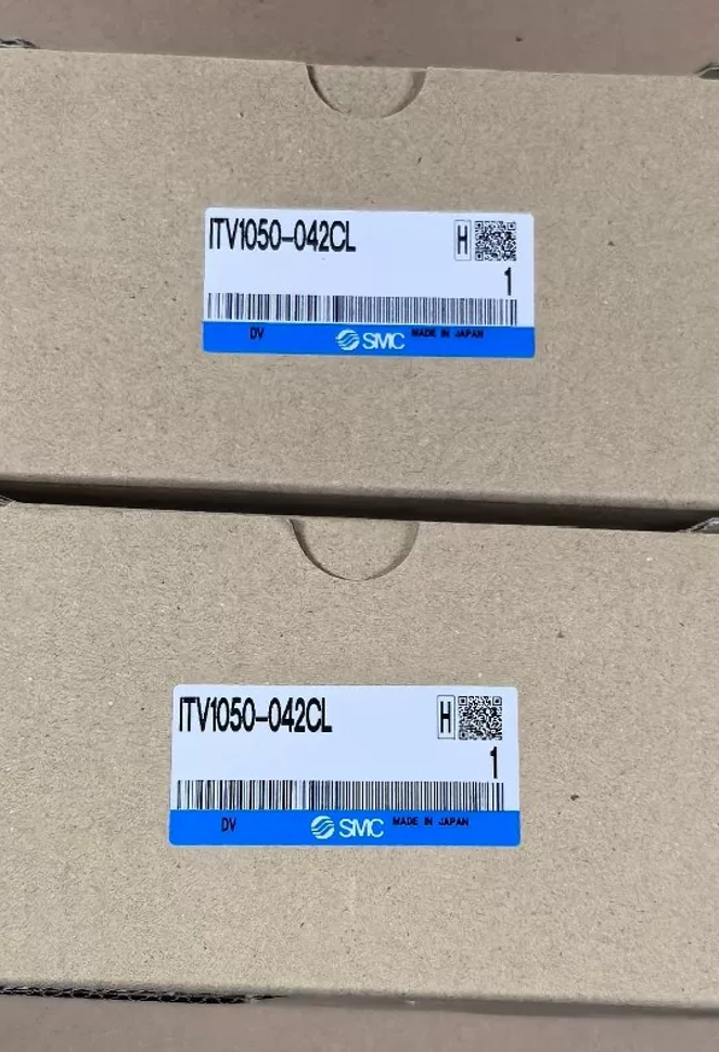

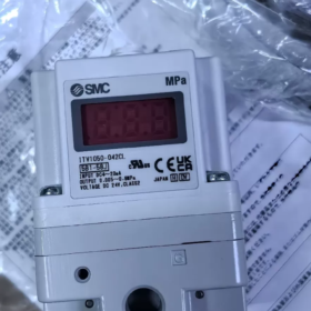
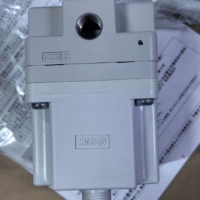
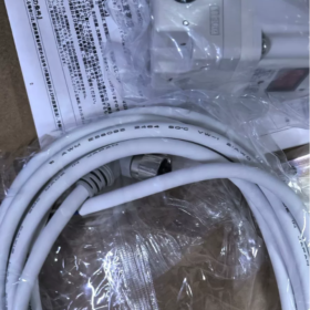
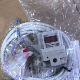
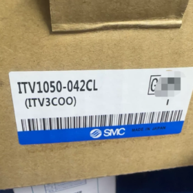
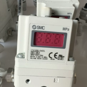
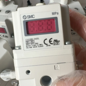
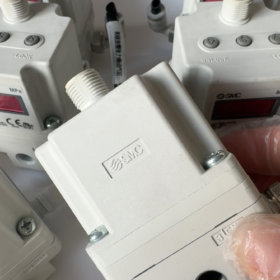
ITV1050-042CL
- ITV: SMC Electro-Pneumatic Regulator Series
- 10: 1000 Serie (compact single-body unit)
- 50: Output pressure range 0.005~0.9 MPa
- 0: Power supply DC24V; Control input 4~20mA (Sink type)
- 4: Monitor feedback output 4~20mA (Sink type)
- 2: Port thread Rc1/4
- C: Equipped with L-shaped mounting bracket
- l: Cable connector right-angle type with 3m cable
Comparison Reference:
ITV1050-042N = Without cable; ITV1050-042S = Straight cable; suffix L stands for right-angle outlet.
- Specifiche tecniche principali
| Articolo | Parametro |
| Output Pressure Range | 0.005~0,9 MPa |
| Massimo. Supply Pressure | 1.0 MPa; Minimum supply pressure = Target output pressure + 0.1 MPa |
| Alimentazione elettrica | DC24V ±10%, Current consumption ≤0.12A |
| Control Input | 4~20mA DC (Lavello) |
| Uscita feedback pressione | 4~20mA DC (Lavello) |
| Linearità | ±1% F.S. |
| Isteresi | ≤0,5% F.S. |
| Ripetibilità | ±0,5% F.S. |
| Sensibilità | 0.2% F.S. |
| Protezione dall'ingresso | Corpo IP65, Connettore IP67 |
| Temperatura operativa | 0~50℃ (mezzo aereo, nessuna condensa) |
| Specifica del porto | RC1/4 (Fornitura SUP / Uscita OUT / Scarico scarico) |
- Definizione dei pin del cavo (Cavo ad angolo retto da 3 m)
Assegnazione del colore dei fili:
Marrone: CC 24 V+
Blu: CC 24 V 0 V (Potenza negativa)
Bianco: 4~ Segnale di controllo 20 mA +
Nero: 4~ Uscita feedback pressione 20 mA +
⚠️ Nota critica: Il terminale negativo del segnale deve condividere la massa comune con il negativo dell'alimentazione. Il cablaggio flottante è vietato.
- Definizione del porto
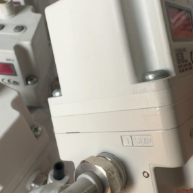
SUP: Ingresso aria di alimentazione
FUORI: Carica l'uscita (collegarsi al cilindro, apparecchio, ugello)
SCAR: Porta di scarico; Non bloccare. Montare il silenziatore in ambienti polverosi.
- Applicazioni tipiche
Regolazione della pressione per il taglio laser, controllo della tensione del film, pressatura di precisione, controllo della pressione di spruzzo, bloccaggio a vuoto di semiconduttori, simulazione della pressione a gradini per apparecchiature di prova, controllo pneumatico della tensione tessile.
- Selezione & Guida alla sostituzione
- Scambio diretto all'interno della stessa serie: ITV1050-042CL non può essere sostituito con ITV1050-312CL (312 è un ingresso di tensione 0–10 V).
- Alternativa all'aggiornamento: Serie ITV2050 di nuova generazione (dimensione maggiore, maggiore capacità di flusso).
- Promemoria per le alternative domestiche: Tipo di segnale (Pozzo/Sorgente) è soggetto a collegamenti errati; verificare sempre l'input & specifiche del segnale di uscita.
- Punti comuni per la risoluzione dei problemi
- Pressione di uscita instabile: Verificare che il differenziale di pressione di alimentazione sia ≥0,1 MPa, perdita della linea d'aria, volume di carico eccessivo.
- Segnale di feedback alla deriva: Garantire una bassa ondulazione dell'alimentazione, messa a terra dello schermo, e separare i cavi di segnale dai cavi di potenza.
- Visualizzazione del pannello “LOC”: Tenere premuto il pulsante sinistro per sbloccare il menu dei parametri.
Caratteristiche di flusso di SMC ITV1050-042CL (Serie ITV1050)
ITV1050-042CL appartiene alla serie compatta ITV1000 con porte Rc1/4 e campo di pressione 0,005~0,9 MPa. I parametri di flusso sono identici per tutte le varianti ITV1050 (i suffissi influiscono solo sul segnale, staffa e cavo; il passaggio del flusso interno rimane invariato).
- Portata nominale (Condizione di prova standard)
Condizione di prova: Pressione di alimentazione Ps=1,0 MPa, impostare la pressione di uscita 0.6 MPa, aria normale (ANR)
- Flusso di carica massimo (SUP→FUORI): ≈200 l/min (ANR)
- Flusso estenuante massimo (USCITA→SCARICO): ≈120 l/min (ANR)
✅ Caratteristica fondamentale: Il flusso di scarico è inferiore al flusso di carica. Il rilascio della pressione di carichi di grande volume sarà significativamente più lento dell'accumulo di pressione.
- Parametri della capacità di flusso (Notazione pneumatica standard SMC, ISO 6358)
Conduttanza sonica C (Ricarica SUP→OUT): 0.13 dm³/(s·bar)
Conduttanza sonica C (OUT→EXH estenuante): 0.08 dm³/(s·bar)
Rapporto di pressione critica b ≈ 0.5
Questi valori possono essere adottati direttamente per il calcolo simulato del tempo di carico/scarico per serbatoi e bombole d'aria.
- Regole caratteristiche del flusso (Proprietà principali)
- Flusso regolato non lineare
L'ITV non è una valvola di strozzamento continua. Adotta due elettrovalvole ad alta velocità integrate (valvola di carica + valvola di scarico) controllato da PWM:
Mantenimento della pressione costante: Charge and exhaust valves nearly closed, only minor leakage compensation;
Pressure rising: Charge valve adjusts intake flow by varying PWM duty cycle;
Pressure falling: Exhaust valve adjusts exhaust flow by varying PWM duty cycle.
👉 Output flow is not constant; it dynamically changes with pressure differential and target pressure deviation.
- Influence of pressure differential
Larger differential between supply and output pressure enables higher instantaneous maximum flow;
Minimum supply pressure requirement: Supply pressure ≥ Target output pressure + 0.1 MPa
If the pressure differential is less than 0.1 MPa, maximum flow drops sharply and pressure response slows down.
- Coupling between load volume and dynamic response
Small-volume loads (suction fixture, ugello): Excellent pressure tracking performance;
Large-volume air tanks / large-bore cylinders: Longer charging & tempo estenuante, incline al superamento.
Esperienza di ingegneria: Installare una valvola di scarico rapido esterna per accelerare il rilascio della pressione se il volume è >1 L.
- Tempo di risposta (Indicatore dinamico correlato al flusso)
Condizione di prova: Pressione di alimentazione 1.0 MPa, volume di carico 50 ml
Tempo di salita 0→0,5 MPa: ≤0,8 secondi
Tempo di caduta 0,5→0 MPa: ≤1,0 s
Il tempo di ricarica e di scarico aumenta in modo approssimativamente lineare con il volume di carico.
- Limitazioni all'utilizzo relative al flusso (Evitare le trappole della selezione)
- Non adatto per il funzionamento continuo ad alto flusso
L'ITV1000 è un regolatore proporzionale con priorità alla pressione. Il suo obiettivo progettuale è la stabilizzazione della pressione. Funzionamento a lungo termine vicino al massimo 200 Il flusso l/min causerà il surriscaldamento della valvola pilota interna e la fluttuazione della pressione.
Soluzione per applicazioni continue ad alto flusso: Utilizzare l'ITV per pilotare un regolatore di pressione esterno di grande capacità.
- La perdita di pressione nella linea riduce notevolmente il flusso effettivo
Diametro interno consigliato del tubo ≥6 mm; i tubi sottili e lunghi rendono il flusso effettivo al carico molto inferiore a quello nominale 200 l/min.
- Non bloccare la porta di scarico
L'attacco di scarico bloccato riduce drasticamente la capacità di scarico e rallenta il rilascio della pressione. Adatta silenziatori compatti in ambienti polverosi.
- Confronto della capacità di flusso all'interno delle serie
| Serie | Massimo. Flusso di carica (ANR) | Posizionamento |
| ITV1050 (questo modello) | 200 l/min | Compatto, portata medio-bassa |
| ITV2050 | 800 l/min | Flusso medio |
| ITV3050 | 4000 l/min | Flusso elevato |
Scenari applicabili per le curve caratteristiche di flusso di SMC ITV1050-042CL
Premessa fondamentale:
ITV1050 è un regolatore elettropneumatico a circuito chiuso controllato dalla pressione, azionato da valvole di commutazione ad alta velocità PWM. Le curve caratteristiche di portata fornite nella scheda tecnica (flusso massimo rispetto alla pressione di uscita, capacità di carica/scarico, Curve del valore C) descrivere la capacità finale di alimentazione/scarico dell'aria della valvola in base a diversi differenziali di pressione.
NON equivale alla curva di flusso di una valvola a farfalla proporzionale. Le curve possono essere utilizzate solo per valutare la velocità di aumento/rilascio della pressione e il consumo d'aria massimo consentito, e non può essere applicato per un controllo preciso del flusso.
- Scenari in cui le curve di flusso possono essere utilizzate direttamente per il calcolo & Verifica
- Carichi chiusi a volume fisso (Applicazione più tipica)
Carichi: Serbatoi d'aria, cavità di aspirazione, camere di prova ermetiche, piattaforme aspiranti a vuoto, attrezzatura chiusa per la regolazione della pressione
Scopo:
Calcolare il tempo di aumento/rilascio della pressione con le curve di flusso e i valori C, verificare il volume massimo consentito della cavità, prevedere la velocità di risposta alla commutazione della pressione, e giudicare una risposta insufficiente o un superamento della pressione.
Limite di riferimento: Volume consigliato ≤1 L; valutare valvole di scarico rapido esterne per volumi maggiori.
- Corsa breve, attuatori pneumatici a basso consumo d'aria
Carichi: Cilindri a membrana a corsa breve, teste di pressatura di precisione, cilindri di serraggio, microcilindri di sollevamento
Applicazioni: Pressatura di precisione, attrezzatura per la laminazione, controllo della pressione di piccoli apparecchi
Obiettivo della verifica:
Il consumo istantaneo di aria durante il movimento del cilindro deve essere inferiore al flusso massimo di carica (200 ANR l/min) per evitare cadute di pressione e perdita di stabilità durante il funzionamento.
- Uscita d'aria continua stabile a basso flusso (ugelli, barriere d'aria, soffiaggio d'aria)
Carichi: Ugelli di soffiaggio di piccolo diametro, barriere d'aria strette, soffiaggio ausiliario laser, piccoli ugelli per l'aria di raffreddamento
Prerequisito: Consumo d'aria continuo e stabile, flusso a lungo termine <150 l/min
Funzione della curva: Verificare che il consumo d'aria continuo non superi la capacità di flusso finale della valvola; valutare la perdita di flusso causata dalla caduta di pressione della tubazione.
Attenzione: Evitare il funzionamento a lungo termine vicino a 200 Limite di flusso l/min, che porta al riscaldamento continuo delle elettrovalvole interne e all'oscillazione della pressione.
- Test dinamico del ciclo di pressione a gradini
Il processo richiede frequenti passaggi tra più livelli di pressione impostati (prova di impatto ciclico ad alta/bassa pressione)
Le curve di flusso vengono utilizzate per stimare la durata dell'aumento/diminuzione della pressione, confrontare con il tempo di commutazione del processo consentito, e valutare se aggiungere accumulatori d'aria o valvole di scarico rapido esterne per ottimizzare il rilascio della pressione.
- Scenari in cui le curve di flusso servono solo come riferimento approssimativo, Simulazione accurata non fattibile
- Corsa lunga, cilindri di grosso diametro a moto alternativo continuo
I cilindri consumano continuamente aria e formano carichi di flusso dinamicamente variabili. La caduta di pressione si verifica quando il consumo d'aria si avvicina al limite di flusso della valvola. La curva di flusso può solo giudicare il limite di flusso superiore e non può calcolare con precisione la velocità operativa del cilindro.
Suggerimento di ingegneria: Adottare lo schema di “Pilota dell'ITV + regolatore di pressione di grande capacità” per condizioni di elevato consumo d'aria.
- Carichi con frequenti e drastiche fluttuazioni del flusso e senza volume tampone
La variazione improvvisa del flusso d'aria innesca facilmente l'oscillazione della pressione. Le curve di flusso statiche non possono caratterizzare il comportamento di oscillazione dinamica e possono essere utilizzate solo come riferimento preliminare per la selezione.
- Scenari in cui le curve di flusso sono completamente inapplicabili – Uso improprio severamente vietato
- Processi che richiedono un controllo preciso del flusso di gas (erogazione a flusso costante, microregolazione del flusso d'aria)
L'ITV mira al controllo della pressione. La portata varia automaticamente con il differenziale di pressione tra ingresso e uscita; il flusso rimane incoerente con la stessa pressione impostata. Le curve di flusso non possono essere utilizzate come base di controllo. Dovranno invece essere selezionate valvole di flusso proporzionali elettropneumatiche.
- È richiesto un controllo del flusso di scarico indipendente e preciso
L'ITV implementa solo il controllo a circuito chiuso della pressione. Il flusso di scarico viene regolato indirettamente tramite il feedback della pressione. Non è possibile ottenere una regolazione stabile e indipendente del flusso di scarico.
- Progettazione di condizioni di lavoro continue ad alto flusso
Consumo d'aria continuo a lungo termine >150 L/min; La guida diretta tramite ITV non è consigliata.
- Riepilogo di ingegneria
✅ Adatto per applicare curve di flusso per la risposta, verifica del volume e del consumo d'aria:
Regolazione della pressione a cavità chiusa | Piccoli cilindri a corsa breve | Soffio d'aria stabile a basso flusso | Test ciclico di pressione
⚠️ Solo riferimento approssimativo: Cilindri a corsa lunga di grande diametro, carichi con frequenti fluttuazioni del flusso
❌ Non applicabile: Controllo costante del flusso, precisa regolazione indipendente del flusso di scarico





NH42-63-318x560.png "Commutatori automatici di tipo PC CHINT (ATS)NH42-63/4SZ")



