 コンタクタ,サーキットブレーカー,センサー,エンコーダ,PLC,コンバータ

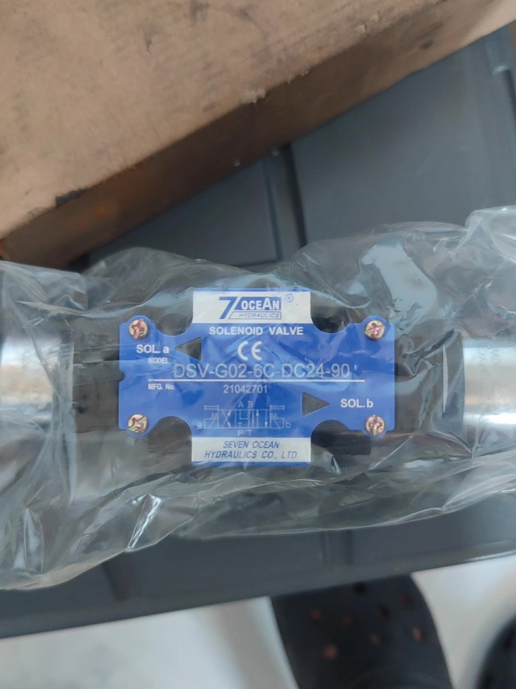

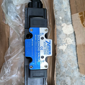
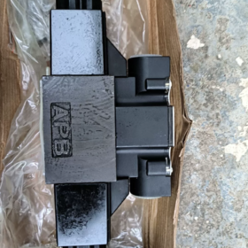
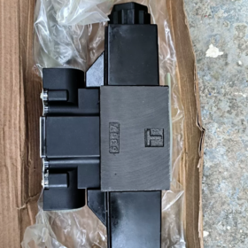
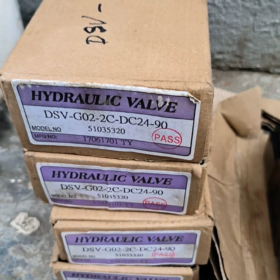
DSV-G02-2C-DC24-90
- DSV: Solenoid directional valve, terminal box type solenoid
(DSD = DIN connector type; identical mounting subplate for both versions)
- G02: Size NG6 / CETOP-03 / D03 (6 nominal diameter)
- 2C: 4/2-方法, ダブルソレノイド, スプリングリターン
Spool function: Spring return initial position; energize one solenoid → P→A, B→T; energize the other solenoid → P→B, A→T
- DC24: コイル電圧 DC24V
- 90: タイプ 90 wet armature high-power solenoid
Suffix options: 20,72,82 represent different solenoid specifications. Solenoids are NOT interchangeable.
- 主要な技術仕様
取付規格: CETOP RP121H, D03 size subplate mounting
マックス. 使用圧力: 35 MPa (350 バー)
マックス. Allowable Tank Back Pressure: 22 MPa
Rated Flow: ≤110 L/min
Hydraulic Fluid: Hydraulic oil (ISO VG32 / ISO VG46)
Fluid Temperature: -20 ~ +70℃
Solenoid: DC24V Type 90 wet armature solenoid, 100% 継続勤務 (ED100%)
Valve Weight: 約. 2.6 kg
- Key Distinction Points
- DSV vs DSD-G02
DSV: External terminal box (ネジ配線) – 指定どおりのモデル DSV-G02
DSD: DIN43650 クイックプラグコネクタ
→ 同一の内部流路; ソレノイド配線ハウジングのみが異なります.
- 2Cスプール機能
✅ 4/2ウェイダブルソレノイドスプリングリターン; 中立の立場がない. 停電時にバルブは自動的に初期位置にリセットされます.
- 種類に関する注意事項 90 Solenoid
サフィックスを厳密に指定する -90 調達・交換時. に置き換えられました -20 シリーズソレノイドでは作動力が不足します, オーバーヒートと鈍いシフト.
- 同等 & 代替モデル
- オリジナルの同一ユニット: DSV-G02-2C-DC24-90
- 代替配線バージョン: DSD-G02-2C-DC24-90 (プラグタイプ, 互換性のあるサブプレート)
- 国内互換同等品: WF, 英国DSG-01-2B2-D24シリーズ
(取付寸法に近い; スプール機能の検証が必要です)
- 典型的な故障診断
- シフトが遅い、または失敗している: 不足電圧, ソレノイドの種類が一致していません, 汚れたオイルによるスプールの焼き付き
- コイル過熱 & 燃え尽き症候群: 継続的な過負荷, 電圧変動, 内部短絡
- 内部漏れが多い: スプールの摩耗, 圧力保持不良
7オーシャン DSV-G02-2C-DC24-90 (NG6 D03 4/2方ダブルソレノイドバルブ) 完全なインストール手順
サブプレート取付型油圧ソレノイド方向切換弁に適用可能
DSV: 端子箱ソレノイド; DC24V Type90ハイパワー湿式アーマチュアコイル; 2C ダブルソレノイドスプリングリターン
⚠️ オペレーターは油圧を保持する必要があります & 電気工事士資格. 作業前に油圧システムの圧力を抜き、電源を切ってください。!
- 設置前検査 (必須)
1.1 材質の検証
バルブ型式: DSV-G02-2C-DC24-90. 電圧DC24Vを確認, スプールコード2C, ソレノイドの接尾語 90
付属品: 標準 G02 サブプレート (CETOP03/D03), 4M6六角穴付きボルト 個, 4P/A/B/T ポートシール用 O リング
目視チェック: バルブボディへの影響なし, コイルの亀裂または破片がオイルポートをブロックしている.
1.2 システム & 環境チェック
周囲条件: -20~70℃, 相対湿度<90%RH, 結露なし; 熱源から遠ざけてください, 溶接スパッタや激しい振動
作動油の清浄度: NAS 8 またはそれ以上の; 吸引ラインに100メッシュ以上のフィルターを取り付けてください
システムの最大圧力は 35MPa を超えてはなりません.
1.3 ツールの準備
M6六角ソケットレンチ, トルクレンチ, 糸くずの出ない布, 乾式圧縮空気銃, マルチメータ, 絶縁ドライバー.
- サブプレート & バルブの取り付け
ステップ 1: きれいなシール面 (スプールの固着を防ぐために重要)
- 乾燥した圧縮空気を使用して、サブプレート取り付け面およびバルブ底部シール面の破片を吹き飛ばします。
- 糸くずの出ない布で表面を拭きます; 鉄粉を除去する, ゴムの破片と残留油
- フィット 4 バルブ底部の P/A/B/T の凹部に O リングを挿入. O リングのねじれや外れを避けてください。.
ステップ 2: バルブ本体の位置を決めて固定します
- ソレノイドバルブをG02サブプレートに平らに置きます; バルブとサブプレートの間のP/A/B/Tポートの位置を合わせます
ポートのマーキング: P=圧力入口, T=タンクリターン, A/B=アクチュエータの動作ポート
- 入れる 4 M6 ボルトとネジを手動で行うことで、傾くことなく完全に接触します。
- ボルトを対角に2~3回に分けて締めます
✅ 標準締め付けトルク: 5.5~6.5N・m
❌ 単一のボルトを連続して完全に締めないでください。. 過大なトルクによりOリングが潰れ、内部漏れが発生します。; トルク不足により高圧外部漏れが発生する.
- 推奨取付姿勢: 水平設置, ソレノイドは左側に配置 & 右水平 (ダブルソレノイドの自然なレイアウト). 小さい傾斜角は許容されます; 長期間の逆さ設置は推奨されません.
ステップ 3: サブプレートに油圧配管を接続します
- 油圧ホースをネジ付きポート P に接続します。, T, あ, サブプレートのB
- サブプレートへの外部からの引っ張り力を防ぎ、せん断荷重とシール漏れを防ぎます。
- マックス. Tリターンラインの許容背圧 ≤22MPa; 適切な呼び径で戻り配管を短く保つ.
- 電気配線 (DSV端子箱バージョン, DC24Vコイル)
デュアルソレノイドを搭載したバルブです (左ソレノイド, 右ソレノイド), DC24V, 極性敏感!
⚠️配線は電源を切ってから行ってください。. 活線禁止!
- 端子箱カバーのネジを外し、筐体を開けます
- 各ソレノイドは独立した端子セットを備えています:
各コイルの端子: DC24V(+), DC24V(-); DC コイルの極性は必ず守る必要があります
PLC/リレー出力: 2 つの独立した制御信号. 左同時通電 & 右側のソレノイドは厳禁です!
- 銅製制御ケーブル ≥0.75mm² を使用してください; 端子を確実に圧着; ショートを引き起こす緩んだワイヤを避けてください
- 端子に張力がかからないようケーブルを適切に配線します; 端子箱ダストカバーを取り付けます
- マルチメーターによる事前テスト: 電源オフ状態での両方のコイルの抵抗を測定します. 抵抗が無限である場合はコイルの開回路を示します.
- システムのフラッシング & 無負荷試運転 (全負荷圧力を直接加えないでください。)
4.1 初期フラッシング
- すべてのボルトとパイプの接続が完了していることを確認します
- ジョグ油圧ポンプ, 低圧下でスタートする (3~5MPa), 5~10分間循環洗浄システム
- バルブとサブプレートの間のシール接合部の外部へのオイル漏れを検査します。. 漏れが発生した場合, 減圧してボルトを均等に締め直します.
4.2 電気ジョグテスト (低圧またはゼロ圧力)
- 低い油圧を維持する
- 左右のソレノイドを別々に短パルスで通電 (1毎回 ~2秒)
- 通常のフィードバック: 明確な “クリック” 通電時に音を切り替える
音が出ない: 供給電圧が低い, 間違った配線, 損傷したコイル
異音 / 切り替えなし: 汚れたスプール; バルブの分解と清掃が必要
安全規則: 両方のソレノイドが同時に通電されないように制御プログラムにインターロックを実装します。!
4.3 負荷漸次圧力試験
- 低圧切り替えが成功した後, 作動圧力を段階的に上げます
- 往復スイッチングを繰り返し実行し、アクチュエータの動きを観察します。:
左ソレノイド通電→P→A, B→T
右ソレノイド通電→P→B, A→T
停電→スプリングによりスプールが初期位置に自動復帰
- 継続的に実行する 30 検査にかかる分: シール面に漏れがない; 異常な過熱のない正常なコイル温度.
- 禁止操作ルール (設置の赤い線)
- ❌ バルブをこじ開けたりクランプしたりするためのてこの作用点としてソレノイドハウジングを使用しないでください。
- ❌ サブプレート上の鉄粉を除去せずに取り付けないでください。. シール面に傷がつき、スプールの焼き付きが発生します
- ❌ M6 ボルトのトルク制限を超える, Oリングが潰れ、継続的な内部漏れが発生します。
- ❌ DC24V 電源の長期逆極性, ソレノイドの寿命が短くなります
- ❌デュアルソレノイド同時通電, コイルの焼損や内部スプリングの損傷につながります。
- ❌ T リターンラインの詰まりまたは過剰な背圧によりスイッチング障害が発生する
- ❌ ひどく汚染された作動油を使用してシステムを直接操作する.
- 設置後のオンサイトトラブルシューティング
- バルブとサブプレート間の油漏れ: ボルトを減圧して対角に増し締めする; 壊れた、または間違った位置にある O リングを確認してください
- 切り替えられません: コイル電圧を測定する, 配線の極性を確認してください; 汚れたオイルが焼き付きを引き起こす場合は、スプールを掃除してください
- 遅いスイッチング: Type90 ソレノイドが装備されていることを確認します; Type20/72低推力ソレノイドは代替不可; ケーブルの過度の電圧降下を確認してください
- コイルの急速な過熱と焼損: 長時間連続通電 (バルブはED100%の連続運転をサポートします, ただし2コイル同時通電禁止) または供給電圧を超えています.
7OCEAN DSV-G02-2C-DC24-90 Complete Technical Data
- モデルコードの定義
DSV-G02-2C-DC24-90
- DSV: Wet armature solenoid directional valve, screw terminal box solenoid
(DSD = DIN quick plug type; identical flow body)
- G02: Mounting standard NG6 / CETOP03 / ISO4401-AB-03-4-あ (6 nominal diameter)
- 2C: 4/2-方法, ダブルソレノイド, bi-directional spring return
De-energized initial position: P↔B, A↔T
SOL.a (Left Coil) 元気が出る: P↔A, B↔T
SOL.b (Right Coil) 元気が出る: P↔B, A↔T
⚠️ Never energize both solenoids simultaneously
- DC24: Nominal control voltage DC24V
- 90: Type90 high-power wet armature solenoid
Greater actuating force for high-pressure applications; not interchangeable with 20/72/82 ソレノイド.
- Hydraulic Performance Data
| アイテム | 仕様 |
| バルブの種類 | Direct operated wet solenoid directional valve|4/2-way double solenoid spring return |
| 呼び径 | 6 mm (NG6 / D03) |
| マックス. 使用圧力 (P,あ,B Ports) | 35 MPa (350 バー) |
| マックス. Allowable Tank Back Pressure (T Port) | 22 MPa |
| Rated Flow | ≤63 L/min (at pressure drop ΔP=1MPa) |
| Recommended Operating Flow | ≤60 L/min. Higher flow causes excessive pressure drop and delayed switching |
| Switching Response Time (DCコイル) | Actuate:10~15ms; スプリングリセット:10~15ms |
| マックス. スイッチング周波数 | 300 1分あたりのサイクル数 |
| 作動流体 | 鉱物性作動油 ISO VG32 / VG46 |
| 流体の動粘度 | 15~400mm²/秒 |
| 必要な油の清浄度 | NASクラス 8 またはそれ以上の; ろ過≧25μm |
| 流体温度範囲 | -20 ℃~ +70 ℃ |
| 標準シール材質 | NBRニトリルゴム; オプションの高温用FKMフッ素ゴム & 耐薬品性 |
- 電気データ (Type90 DC24V ソレノイド)
| アイテム | パラメータ |
| 定格電圧 | DC24V (許容誤差±10%, 21.6~26.4V) |
| コイルのデューティサイクル | ED=100% (連続通電可能) |
| 定格電力 (シングルコイル) | 約. 31 W |
| コイルの直流抵抗 (20℃) | 約18~22Ω (測定範囲) |
| ソレノイドの構造 | ウェットアーマチュア設計, 低騒音, 動作圧力下でシフト可能 |
| 侵入保護 | IP65 (完成した端子箱) |
| 配線方法 | 端子箱のネジ端子; DCの極性依存 |
| 推奨コントロールケーブル | ≥0.75 mm² 銅ケーブル |
- 機械式 & 実装データ
- 取付規格
実装パターン: ISO 4401-AB-03-4-あ (CETOP RP121H / DIN24340 タイプA)
マッチングアクセサリー: G02標準サブプレート
- 締結ボルト
仕様: M6六角穴付きボルト×4本
標準締付トルク: 5.5~6.5N・m (斜め段階締め)
- 重さ
デュアルソレノイドを備えた完全なバルブ: 2.05 kg
- 推奨取付姿勢
水平設置を推奨; 傾きは許可されています; 長期間の逆さ設置は推奨されません.
- スプール機能の説明 (2Cスプール)
通電されていない (春の帰還): P ↔ B, A ↔ T
左ソレノイド SOL.a 通電: P ↔ A, B ↔ T
右ソレノイド SOL.b 通電: P ↔ B, A ↔ T
中立位置のない2ポジションバルブです。. いずれかのソレノイドの電源が切られると、スプールはすぐに初期位置に戻ります.
- 選択 & 特記事項
- DSV vs DSD-G02
同一のフローボディ, 取付寸法とスプール機能; ソレノイド配線インターフェースのみが異なります:
DSV = ネジ端子箱配線; DSD=DIN43650プラグ接続.
- ソレノイドのサフィックス: 90 / 82 / 72 / 20
90式: 高推力バージョン, 高圧に適した, 重負荷および低油温条件 (このモデルの標準)
タイプ20/72/82: 標準推力タイプ. 高圧下ではシフト力が不十分になる危険性; Type90 ソレノイドを直接置き換えることはできません
- 回路警告
制御ロジックは 2 つのスイッチング信号の同時出力を避ける必要があります. 2コイル同時通電により急激な温度上昇やソレノイドの焼損が発生します. 電気的インターロック回路は必須です.
- 代表的なアプリケーション業界
工作機械の油圧ステーション, 射出成形機, 自動化された生産ライン, 木工機械, 油圧治具, 昇降プラットフォーム, 建設機械用補助油圧回路.





NH42-63-318x560.png "CHINT PC型自動切替スイッチ (ATS)NH42-63/4SZ")



