 コンタクタ,サーキットブレーカー,センサー,エンコーダ,PLC,コンバータ

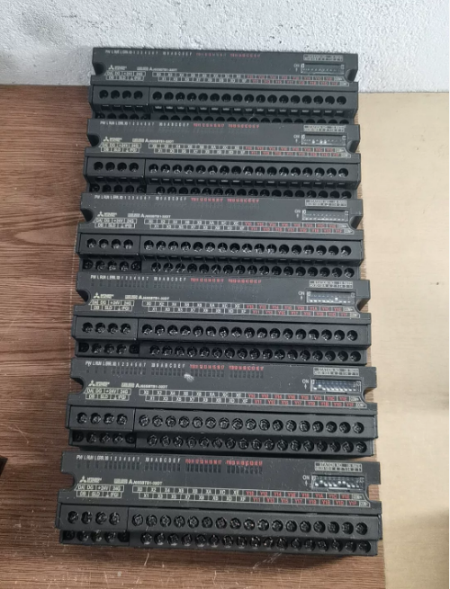

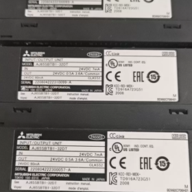
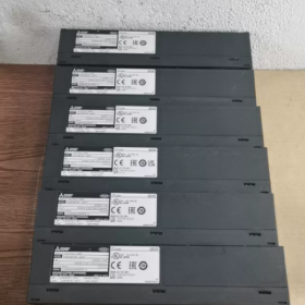
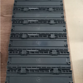
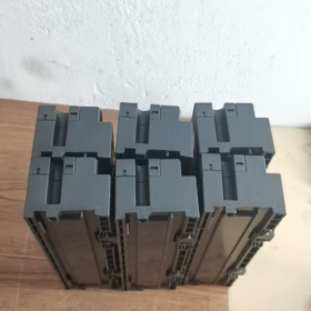
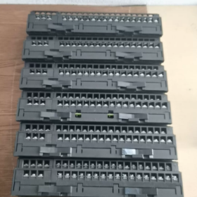
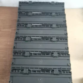
- モデルの定義 & 製品のポジショニング
AJ65SBTB1-32DT: CC-Link用小型ネジ端子台タイプリモート混合I/Oモジュール
AJ65SB: CC-LinkリモートI/O シリーズ
TB1: 一体型ネジ端子台 (フィンガータッチプロテクションタイプ)
32: 合計 32 I/O点数 (16 入力 + 16 出力)
D: DC24V入力; T: シンクトランジスタ出力
占有します 1 CC-Link局番, マルチステーションの割り当ては必要ありません. Q/L/RシリーズCC-Linkマスタ局に対応 (例えば, QJ61BT11N)
- コアの電気仕様
2.1 入力セクション (16-ポイント DC24V プラスコモン / シンク入力)
| アイテム | 仕様 |
| ポイント数 | 16 ポイント (X0~X15) |
| 定格電圧 | DC24V, 許容範囲 19.2~26.4V (リップル ≤5%) |
| 1点あたりの入力電流 | 約. 7ミリアンペア |
| オン閾値 | ≥14V / ≧3.5mA |
| オフ閾値 | ≤6V / ≤1.7mA |
| 応答時間 (オフ ↔ オン) | ≤1.5ms |
| 分離 | フォトカプラ絶縁 |
| 配線方法 | プラスコモン端子 (+24Vに接続されたCOM, センサーのマイナス線を入力端子に接続) |
2.2 出力セクション (16-ポイントシンクトランジスタ出力)
| アイテム | 仕様 |
| ポイント数 | 16 ポイント (Y0~Y15) |
| 負荷電圧 | DC19.2~26.4V |
| 1点あたりの最大電流 | 0.5A/点; COMごとの合計電流: 3.6あ |
| 突入電流 | ≤1A (継続時間 ≤10ms) |
| オフ時漏れ電流 | ≤0.25mA |
| オン状態の電圧降下 | ≤0.3V (0.5A負荷時) |
| 応答時間 | ≤0.5ms |
| 出力ロジック (シンク) | 負荷の負極を出力端子に接続します; 負荷の正極を外部 +24V に接続します |
2.3 モジュール電源
供給電圧: DC20.4~26.4V
全体の消費電力: ≤60mA (すべての I/O ポイントが同時にオンになります)
- 機械式 & 環境パラメータ
- 全体の寸法: W179mm×H50mm×D40mm
- 重さ: 0.25kg
- 端子: M3ネジ; 7-ピン通信 & パワースプリット端子 + 34-ピン入出力端子台
- 保護クラス: IP2X (指感電防止機能付き端子; 工作機械に直接取り付け可能)
- 動作温度: 0~55℃; 保管温度: -20~75℃
- 湿度: 10~90%RH, 結露なし
- 耐電圧: AC500V用 1 外部DC端子とアース間1分間; 絶縁抵抗≧10MΩ (500VDCでテスト済み)
- 主要な CC-Link ネットワーク配線ガイドライン
- バストポロジ: デイジーチェーン配線; 120バスの両端にΩ終端抵抗を取り付ける必要があります
- 通信ケーブル: CC-Link専用シールド付ツイストペアケーブル
- 最大バス長: 1.2km (10Mbpsハイスピードモード)
- 駅の住所: モジュール側のDIPスイッチで設定 (駅番号. 1~64)
- 端子の定義: DA/DB通信回線, DGシールドグランド, 24Vモジュール電源, FGフレーム保護アース
- シリーズモデルの差別化 (DT / DT1 / DT2)
AJ65SBTB1-32DT: スタンダードモデル; 7mA入力電流, COMあたり最大合計3.6Aの出力電流
AJ65SBTB1-32DT1: 低電流入力 (5ミリアンペア), 2線式近接センサーに最適
AJ65SBTB1-32DT2: 改善された応答モデル; 出力COMのグループ化された電流制限, 強化された耐干渉性能
- 典型的なアプリケーションシナリオ
- 生産ライン向け分散フィールド信号収集, 包装機、射出成形機
- 工作機械に隣接して取り付けられたセンサーや電磁弁の遠隔制御
- 大規模生産ライン向けCC-Link子局増設で盤内配線を削減
- 物流仕分け・コンベアライン向けデジタルリモートI/O子局
- 配線 & 設置禁止事項
- すべての入力 COM 端子は均一に +24V に接続する必要があります; 別々の電源からのアース電位を混合することは禁止されています
- トランジスタ出力はAC負荷を直接駆動できません; 外部リレーは必須です
- 誘導負荷間にフリーホイール ダイオードを並列に接続する (電磁弁) トランジスタの故障を防ぐため
- CC-Linkバスシールド層一点接地; 両端の接地は禁止されています
- 推奨端子線ゲージ: AWG14~16; ネジの締め付けトルク: 0.8~1.0N・m
インストールを完了する & AJ65SBTB1-32DT 三菱CC-LinkリモートI/Oユニット取扱説明書
- ハードウェア構造の説明 (モジュールのフロントパネル)
1.1 LEDステータスインジケーター
| LEDラベル | 正常な状態 | 障害の表示 |
| PW | 常時点灯 | DC24Vモジュール電源正常; OFF = 電源供給なし |
| 走る | 常時点灯 | CC-Link通信正常; OFF = 通信中断 |
| エラー | オフ | 通信正常; 常時点灯 / 点滅 = 障害が検出されました |
| X0~XF / Y0~YF | 対応するLEDが点灯します | それぞれの入力/出力チャンネルがアクティブになります |
1.2 DIPスイッチバンク (2 グループ)
駅番号. スイッチ: 十の位 (40/20/10), 単位桁 (8/4/2/1). 値を加算して固有の局番を設定 1~64
通信速度スイッチ (スピード): 3-ポジションスイッチ (4/2/1) CC-Linkバスの通信速度を設定します。
1.2 端子台分割レイアウト
① 7ピンバス端子: そして, DB, DG, 24V+, 0V-, FG (コミュニケーション + モジュール電源)
② 34ピンI/O端子: X0~X15入力, Y0~Y15出力, 入力COM, 出力COM
1.3 DINレールラッチ
底部のスプリングラッチ, 標準のTH35 DINレールと互換性があります
- 機械的設置手順
2.1 設置環境要件
動作温度: 0~55℃; 直射日光を避ける, ほこり, オイルミスト, 結露および激しい振動ゾーン
放熱クリアランス: モジュールの上下に 10mm 以上の隙間を確保してください; 発熱する接触器や変圧器の近くに取り付けないでください
取付方向: 水平 DIN レール取り付けを推奨; 垂直取り付けでは、水の蓄積による短絡を防ぐために端子を下向きにする必要があります
2.2 DINレール取り付け手順
- 上部モジュールスロットをTH35 DINレールの上端に引っ掛けます。
- ラッチがカチッとロック位置になるまで、モジュールの底部を下に押します。
- 除去: 下部のラッチを押し下げます, モジュールを上に持ち上げて取り外します
2.3 ネジ取付 (DIN レールは使用できません)
モジュールの両側の取り付け穴を M4 ネジと平ワッシャーで固定します。; 締め付けトルク: 0.8~1.1N・m
- DIPスイッチのハードウェア構成 (電源OFFで行う! 電源が入っている状態でスイッチを変更すると、ERR アラームがトリガーされる)
3.1 局番設定 (クリティカル – ネットワーク全体に固有, 重複は許可されません)
ルール: 10の位の値 (40/20/10) + 単位桁値 (8/4/2/1) = 総局数 (範囲: 1~64)
例:
ステーションNo.1: 単位桁のみ 1 スイッチが入った, 他はすべてオフ
ステーションNo.12: 十の位 10 の上 + 単位桁 2 の上 (10+2=12)
ステーションNo.32: 十の桁 20 & 10 の上 + 単位桁 2 の上 (20+10+2=32)
> 警告: 1 つの CC-Link バス上でステーション番号が重複すると、すべてのステーションの通信障害が発生する
3.2 通信速度設定 (QJ61BT11N マスターステーションの速度と完全に一致する必要があります)
| SPEEDスイッチ (4/2/1) | バス伝送速度 | 最大バス長 |
| オフ オフ オフ | 156kbps | 1200メートル |
| オフ オフ オン | 625kbps | 900メートル |
| オフ オン オフ | 2.5Mbps | 400メートル |
| オフ オン オン | 5Mbps | 200メートル |
| オン オフ オフ | 10Mbps | 100メートル |
- ステップバイステップの端子配線ガイド (電源を入れる前にすべての配線を完了してください; 配線中に電源が切れる)
一部 1: CC-Linkバス & モジュール電源 (7-ピン端子)
端子配列: DA→DB→DG→24V+→0V→FG
- 通信ケーブル (専用CC-Linkシールドツイストペア)
そして & DB: すべてのリモート モジュールを直列にデイジーチェーン接続する; バス上の最初と最後のモジュールの DA/DB 間に 120Ω の終端抵抗を接続します。
DG: 通信シールド接続; 1 つのバス端のみでの単一点接地, 両端接地禁止
- モジュール動作電源
24V & 0V: モジュールメインボード用のDC24V電源; 動作範囲 19.2~26.4V
FG: モジュール保護アース, キャビネットのPEアースに接続
> 配線仕様: CC-Link ケーブルを 380V 電源ケーブルから離して配線します。; 30cm 以上の平行距離を維持する; クロス配線は垂直でなければなりません
一部 2: 16-ポイント DC24V シンク入力 (X0~X15)
- すべての入力 COM 端子を DC24V プラスに均一に接続 (+)
- 2 線式センサーのプラス線を 24V に接続します。, X0~X15入力端子へのマイナス線
- 独立した電源を持たないセンサー: 24V+をCOMに直接配線, センサーのマイナス線をX端子に接続
入力ロジック: X端子に0V信号が印加された場合, 対応するX LEDが点灯し、PLC入力がONになります。
一部 3: 16-ポイントシンクトランジスタ出力 (Y0~Y15)
- すべての出力 COM 端子は一律に DC24V プラスに接続 (+)
- ソレノイドバルブのプラス線を接続します / インジケーター負荷はDC24V+, マイナス線をY0~Y15出力端子に接続
- 誘導負荷 (ソレノイドコイル): トランジスタの故障を防ぐために、カソードを +24V に、アノードを Y 端子に接続した並列フリーホイール ダイオードを取り付けます。
- 電流制限: 1点あたり最大0.5A; すべての合計電流 16 ポイント ≤3.6A. 大電流負荷には中間リレーを設置してください
ケーブル仕様 & 締付トルク
ワイヤー断面: 0.3~1.25mm²; M3端子ネジトルク: 0.8~1.0N・m. ネジ山が剥がれるのを防ぐため、締めすぎないでください。
- PLC ソフトウェア構成 (GXワークス2 / GXワークス3; QシリーズマスタステーションQJ61BT11Nの例)
ステップ 1: CC-Linkネットワークパラメータへのアクセス
プロジェクトナビゲーションツリー → [パラメータ] → [ネットワークパラメータ] → [CCリンク]; マスタ局モジュールのスロット位置を選択
ステップ 2: 基本的なバスパラメータの一致
- モード: リモートネットワークVer.1モード
- 通信速度: リモートモジュールのDIPスイッチ速度設定と完全に一致
- 総接続局数: バスで使用する最大駅番号を入力してください (例えば, 入力 10 最高駅Noの場合. は 10)
ステップ 3: AJ65SBTB1-32DT子局追加 (リモートI/Oステーション)
- 駅番号: ハードウェアディップスイッチで設定した局番を入力します (1, 2, 3…)
- 駅の種類: リモートI/Oステーション
- 占有局数: 1 (このモジュールは永続的に占有されます 1 駅の住所)
- 自動割り当てされたリモート XY アドレス: 16 Xアドレスを入力, 16 出力Yアドレス (32 連続ポイント合計)
ステップ 4: パラメータを PLC に書き込み、通信のために電源を投入します
- パラメータを保存してシーケンサCPUにオンライン書き込み
- PLC とリモートモジュールの電源を同時にオンにする; モジュール上の RUN LED の点灯により、通信が正常に行われていることを確認します
- ERR LEDの点滅: 局番を確認する, バスの速度, 終端抵抗とDA/DB線の極性
- 電源投入時のコミッショニング & 操作方法
6.1 正常な通信を確認する
PW常時ON + RUN 常時点灯 + ERR OFF → バス通信リンク確立成功
6.2 入力信号テスト
- トリガーフィールドのプッシュボタン / 光電センサー; モジュール上の対応する X LED が点灯します
- GX Works ソフトウェアによるオンライン監視: 対応するリモート X レジスタが ON 状態に切り替わります
6.3 出力制御テスト
- PLC プログラムで対応するリモート Y レジスタを強制的にオンにします
- モジュール上の対応する Y LED が点灯し、接続された負荷が作動します
6.4 毎日のプログラムの使用法
自動割り当てされたリモート X/Y アドレスを直接読み取り/書き込み; 専用の通信サブルーチンを必要としないローカル I/O と同一のプログラミング ロジック
例: 局番1 AJ65SBTB1-32DT リモートアドレス: X100~X10F (入力), ¥100~¥10F (出力)
- 一般的な障害のトラブルシューティング (LEDの異常 & 対策)
- PW LED消灯: 7 ピン端子の 24V/0V 配線が緩んでいる, 電源障害, 端子ショート
- ランオフ + ERR 常時点灯
マスタステーションのバス速度とモジュールの DIP スイッチ速度の不一致
DA/DB 通信線が逆になっているか断線している
バス端または両端接地に 120Ω 終端抵抗がありません
- 定期的な ERR 点滅: 電源が入っている状態で DIP スイッチが変更される → モジュールの電源をオフにする, スイッチをリセットしてから電源を再投入します
- 入力 LED が点灯しない: COM端子が+24Vから切り離されている, 断線したセンサーワイヤー, DC24V供給電圧が不足しています
- 出力作動なし: 出力 COM に +24V 電源が供給されていない, 負荷短絡, 単一チャンネル過電流 (0.5Aを超える) 保護の発動
- 必須のインストール & 操作の禁止事項
- 通電中にモジュールを抜き差ししたり、DIP スイッチを調整したりすることは固く禁じられています
- CC-Linkバスのシールド層接地はシングルエンドに限定; 両端接地禁止
- トランジスタ出力はAC220V負荷を直接駆動できません; 中間リレーは必須です
- 電位差による誤トリガーを避けるため、入力 COM 端子と出力 COM 端子を別の電源システムに接続しないでください。
- インバータや溶接機などの電磁干渉の強い機器のそばにモジュールを設置しないでください。
- 120バスの両端にΩ終端抵抗を取り付ける必要があります, 長距離通信には必須





NH42-63-318x560.png "CHINT PC型自動切替スイッチ (ATS)NH42-63/4SZ")



