 コンタクタ,サーキットブレーカー,センサー,エンコーダ,PLC,コンバータ

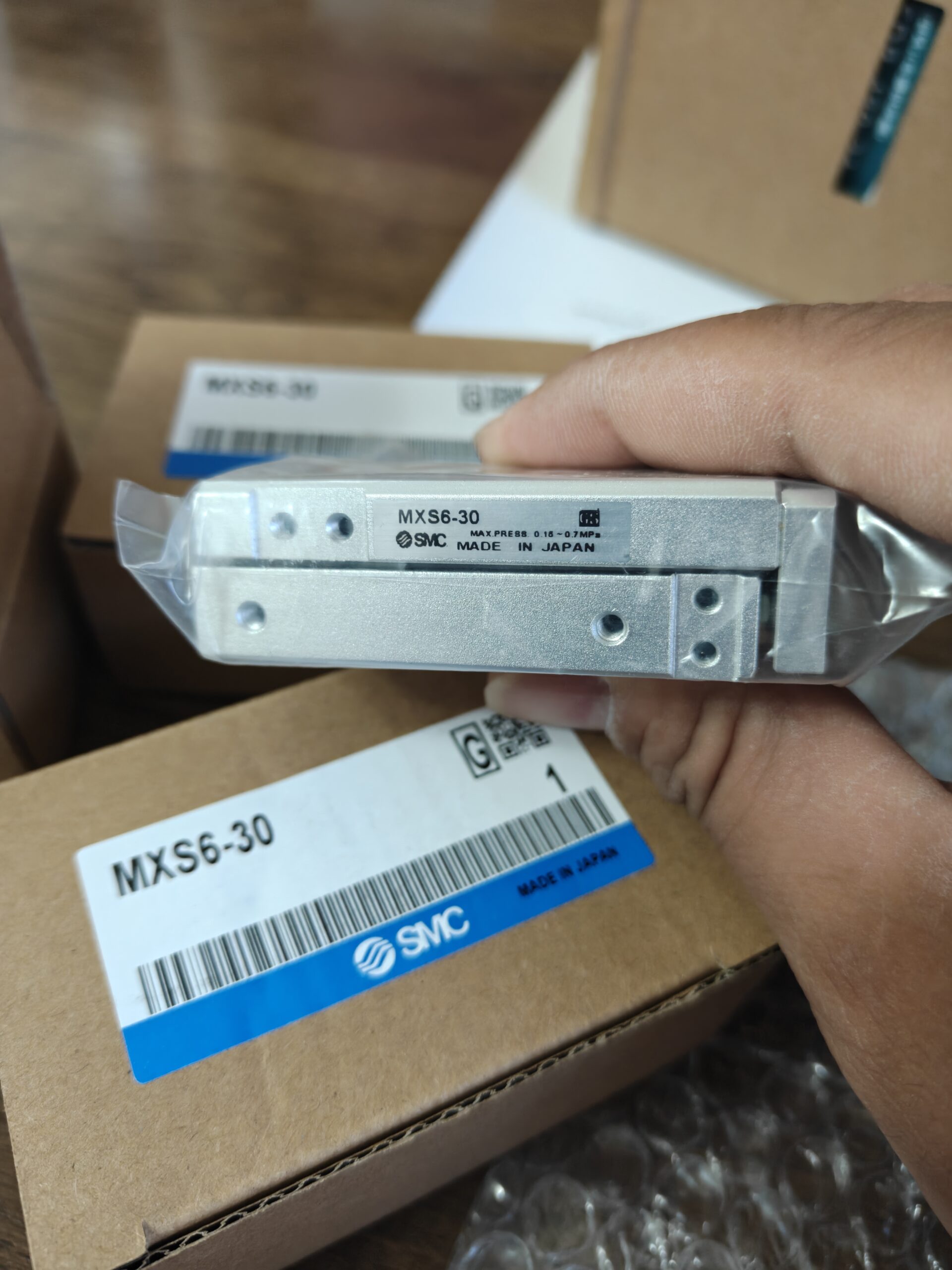

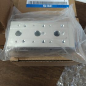
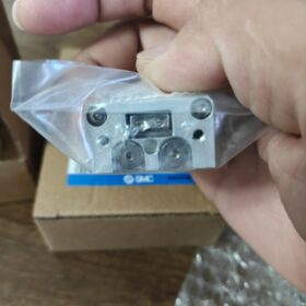
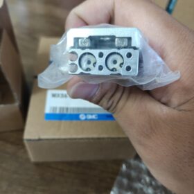
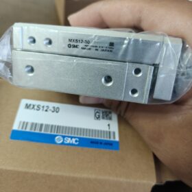
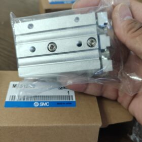
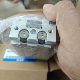
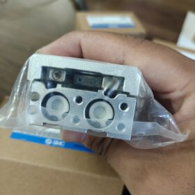
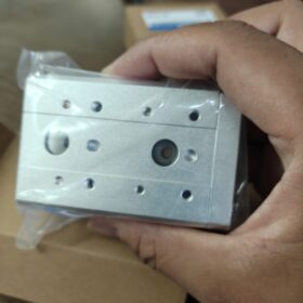
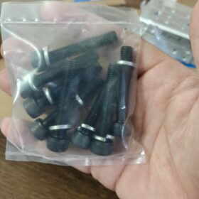
MXS: Dual-cylinder air slide table with cross-roller guide; Bore 6 mm, Stroke 30 mm, 標準タイプ, 複動式, 内蔵磁石, rubber bumpers at both ends
- 型式コードの説明
MXS6-30
MXS: SMC air slide table series (cross-roller guide, dual-cylinder construction)
6: Bore size φ6 mm (dual-cylinder structure)
30: Standard stroke 30 mm
Common suffix extensions:
として: Front-end stroke adjuster; BS: Rear-end stroke adjuster; AT: Dual-end stroke adjuster
B: Hydraulic shock absorber; L: Mirror-image body
–M9BW /-A93: Factory-fitted auto-switches
- 主要な技術仕様
| アイテム | パラメータ |
| アクション | Double‑acting |
| 脳卒中 | 30 mm, stroke tolerance 0~+1 mm |
| 使用圧力 | 0.15‑0.7 MPa; Proof pressure 1.05 MPa |
| ポートネジ | M3×0.5 |
| クッション | Standard rubber bumpers (optional hydraulic shock absorber‑B) |
| Piston Speed Range | 50‑500 mm/s |
| 潤滑 | Non‑lube |
| 周囲温度 | ‑10~+60℃ (アイシングなし) |
| Built‑in Magnet | はい, compatible with auto‑switches |
| Theoretical Thrust @0.5 MPa | Extend 27 N, Retract 21 N |
重さ: 約. 0.22 kg; Optimized for horizontal mounting, suitable for precision short-stroke transfer, positioning and jig actuation.
- Mounting Highlights
- 三面実装: トップ, bottom and side mounting options. Side thread M2.5×0.45. Avoid over-torque and excessive screw depth to prevent guide deformation and jamming.
- Worktable tapped holes M4 for workpiece/fixture mounting.
- Allowable load is governed by moment and overhang length, not only thrust. Longer overhang reduces allowable load.
- Compatible auto-switches: D-M9B/M9N/A93/Z73. Switches install in body T-slots; switches remain stationary (do not travel with slide table).
- 一般的な完全なモデルの例
MXS6-30AS: Front-end stroke adjustable (0-5 mm adjustment range)
MXS6-30BS: Rear-end stroke adjustable
MXS6-30AT: Both-ends adjustable
MXS6-30B: Dual-end hydraulic shock absorbers for reduced impact
MXS6-30-M9BW: Pre-fitted with two M9BW auto-switches
- Domestic Drop-in Replacements (Identical mounting footprint)
北極: HLQ6-30;チェリック: MDX6-30;Direct mechanical interchangeable.
- 使用済み / Second-hand Unit Inspection Checklist
- Supply air at 0.3-0.4 MPa; full-travel smooth operation without sticking or crawling.
- Inspect rubber bumpers for cracking and aging.
- Check lateral play of worktable: Excessive side clearance indicates worn cross-roller guide.
- Air test full-stroke travel; no internal or external air leakage.
- Verify built-in magnet integrity: Auto-switch shall produce valid signal at both end-of-travel positions.
- 代表的な用途
Small-scale automation equipment, 電子機器アセンブリ, jig push-pull, sorting mechanism, miniature transfer positioning.
SMC MXS6-30 Practical Application Cases
MXS6-30 is a φ6 mm bore, 30 mm stroke air slide table with cross-roller guide. Compact size and good moment-resistance capability make it ideal for light-load short-stroke reciprocation. Max allowable horizontal load: 約. 0.6 kg. Widely used in electronics, lithium-ion battery, inspection and small custom automation machines.
Case 1: Electronic component pick-and-place (Consumer electronics assembly machine)
動作状態: Equipped with miniature pneumatic gripper. 30 mm horizontal reciprocation transfers small PCB components from feeder into positioning jig. Cycle time:1.2-2 s/cycle, load 150-250 g.
Selected Model: MXS6-30-M9BW, dual-end auto-switch position feedback.
Design Notes: Minimize overhang. Install flow control valves to set speed 150-250 mm/s to reduce impact. Mount gripper directly onto worktable; body fixed from bottom side.
Why MXS6-30: Superior lateral rigidity compared to MXS-U series. Stable repeatability for reciprocation. Space-saving alternative to servo modules for cost reduction.
Case 2: Camera / Sensor feed positioning (Vision inspection equipment)
動作状態: Drives industrial camera or laser sensor for 30 mm forward-backward offset to inspect workpieces of variable thickness. Stationary imaging at target position, low-frequency cycling.
Selected Model: MXS6-30AS (front-end stroke adjuster, 0-5 mm fine-tuning for inspection distance).
注意事項: Avoid long overhang; mount load close to worktable surface. Stabilize supply air pressure to minimize position deviation caused by pressure fluctuation.
Industry Usage: Connector appearance inspection, plastic part sorting machines.
Case 3: Jig stop / Workpiece positioning (Conveyor line)
動作状態: Stop and pre-position workpieces on conveyor. Slide extends to block workpiece; retracts to release after inspection. 30 mm stroke provides stop-and-clear function.
Selected Model: Standard MXS6-30 with D-A93 auto-switches.
取り付け: Side-wall mounting to save vertical machine height.
注記: Only for light-workpiece stopping. Cannot sustain heavy impact; add dedicated bumper block for high-impact scenarios.
Case 4: Mini-press-fit & connector insertion (Connector assembly equipment)
動作状態: Light pre-press for small connectors and FPC flexible circuits. Slide extends for pre-compression and retracts for retraction. Theoretical extend thrust 27 N @0.5 MPa; suitable only for light-force pressing, not heavy press-fit tasks.
Selected Model: MXS6-30B (hydraulic shock absorber) for high-impact cycles to protect delicate connectors.
リマインダー: If higher pressing force is required, upgrade to MXS8-30.
Case 5: Small-format lithium-ion cell / electrode sorting mechanism
動作状態: Divert qualified / NG miniature soft-pack cells into different bins via 30 mm horizontal push.
Selected Model: MXS6-30-M9N, non-lube design for low-oil-mist battery-plant environment.
制約: Load ≤300 g. Long overhang will accelerate guide wear.
Case 6: Reagent-card / Test-strip pushing for compact medical diagnostic equipment
動作状態: Position reagent cards and test strips in light-load clean-environment setup. Non-lube operation eliminates oil-mist contamination risk.
Selected Model: Standard MXS6-30 with built-in magnet and solid-state auto-switches.
注記: Install air-line oil-mist remover for medical-grade air quality.
Case 7: Single-axis for XY gantry (Compact 2-axis transfer platform)
動作状態: MXS6-30 as X-axis stacked upon second slide table for simple pneumatic XY pick-and-place.
注意事項: Total mass of upper-axis assembly plus workpiece must not exceed allowable load of lower-axis. Avoid large overhang.
⚠️ Common Pitfalls for MXS6-30 Selection
- Max allowable horizontal load 0.6 kg. Allowable load decreases sharply with longer overhang. Moment capacity, not raw thrust, is the primary limiting factor.
- 30 mm is the optimal stroke for bore 6. Rigidity degrades significantly for stroke >40 mm.
- For high-frequency cycling and impact-prone applications, choose -B hydraulic-shock-absorber variant; standard rubber bumpers degrade rapidly under continuous high-speed operation.
- MXS6-30 vs MXQ6-30: MXS uses cross-roller guide with superior moment resistance. MXQ uses ball-bearing guide for lower friction but weaker anti-moment performance, suited for ultra-light-load duty.
SMC MXS6-30 Complete Mounting Instructions
MXS6-30 supports bottom-mount, side-mount and top-mount. Worktable for workpiece mounting; main body fixed to machine frame.
- Thread Specifications & Tightening Torques (SMC factory specification)
- Body mounting (fix cylinder body to machine frame)
Side mounting threads: M2.5×0.45, Max tightening torque 0.5 N·m, Max screw insertion depth 3.5 mm
⚠️Excess-length screws will compress internal guide assembly and cause jamming or permanent damage!
Bottom mounting threads: M2.5×0.45, Max torque 0.5 N·m
- Worktable (mount fixture / workpiece)
Table tapped holes: M4×0.7, Max tightening torque 1.2 N·m
Worktable is moving cross-roller guide assembly. Never over-torque.
- エアポートネジ
ポート: M3×0.5, compatible with miniature pneumatic fittings.
重要: M2.5 screws require low torque value. Torque wrench recommended; 手の感覚に頼らないでください.
- Four Mounting Configurations
1) Bottom-mount (最も一般的な, horizontal orientation)
Fasten screws upward through bottom-body tapped holes. Slide table faces upward, horizontal reciprocation.
応用: Transfer, push-pull, vision feed.
アドバンテージ: Best-case loading condition, maximum allowable load capacity.
注記: Screw insertion depth ≤3.5 mm. Do not contact internal guide components.
2) Side-mount (Wall-mount lateral installation)
Fasten into lateral body tapped holes. Slide table performs horizontal motion while unit stands on its side.
応用: Conveyor-line stop mechanisms, limited-height machine layout.
Side-mount increases applied moment. Derate allowable load. Mount workpieces as close to table surface as possible.
3) Top-mount (オーバーヘッド / inverted mounting)
Fasten body from above. Cylinder hangs upside-down; worktable moves downwards.
Inverted mounting: Workpiece weight fully loads guide system. Load must be derated. Not suitable for high-speed high-cycle operation.
4) Vertical-axis mounting (Up-down motion)
Slide travel oriented vertically. Worktable moves up and down.
❗Risk: Workpiece weight directly alters cushioning performance. Flow-control valves mandatory for low-speed operation. Not for heavy payloads. Recommended vertical-mount payload ≤150 g.
- Auto-Switch Installation
- Auto-switches (D-M9BW / D-A93) install in T-slots on both sides of stationary body, not on moving worktable.
- Loosen slot-clamping screw, slide auto-switch to desired trigger position, 締め直す.
- T-slots available on both sides; 1 または 2 auto-switches may be fitted.
- Mounting Procedure
- Pre-tighten all body-mount screws first, then progressively torque each screw to specified value. Do not fully tighten one screw before others, to avoid body distortion.
- Mount workpiece onto worktable via M4 screws, observe torque limits.
- Air test at 0.3-0.4 MPa for full-stroke smooth operation without sticking.
If jamming occurs: Almost always caused by screws inserted too deep compressing cross-roller guide; reduce screw insertion depth.
- Install flow-control fittings; set piston speed not to exceed 500 mm/s.
- Adjust auto-switch positions and confirm end-of-travel signal integrity.
- Critical Mounting Prohibitions (Frequent Failure Sources)
- Screw insertion depth must never exceed 3.5 mm. Over-length M2.5 screws will destroy guide assembly.
- Do not apply lateral / transverse external forces to worktable; avoid shock-loading the slide.
- Never strike body or worktable after installation; cross-roller pre-load will be lost, creating backlash.
- Vertical-mount applications: Workpiece weight impairs rubber-bumper performance. Select -B hydraulic-shock-absorber model for frequent vertical cycling.
- Do not specify load purely by thrust rating; calculate applied moment. Max allowable moment for MXS6-30: 1.2 N・m.
- Stacked Multi-axis Mounting (XY Platform)





NH42-63-318x560.png "CHINT PC型自動切替スイッチ (ATS)NH42-63/4SZ")



