 コンタクタ,サーキットブレーカー,センサー,エンコーダ,PLC,コンバータ

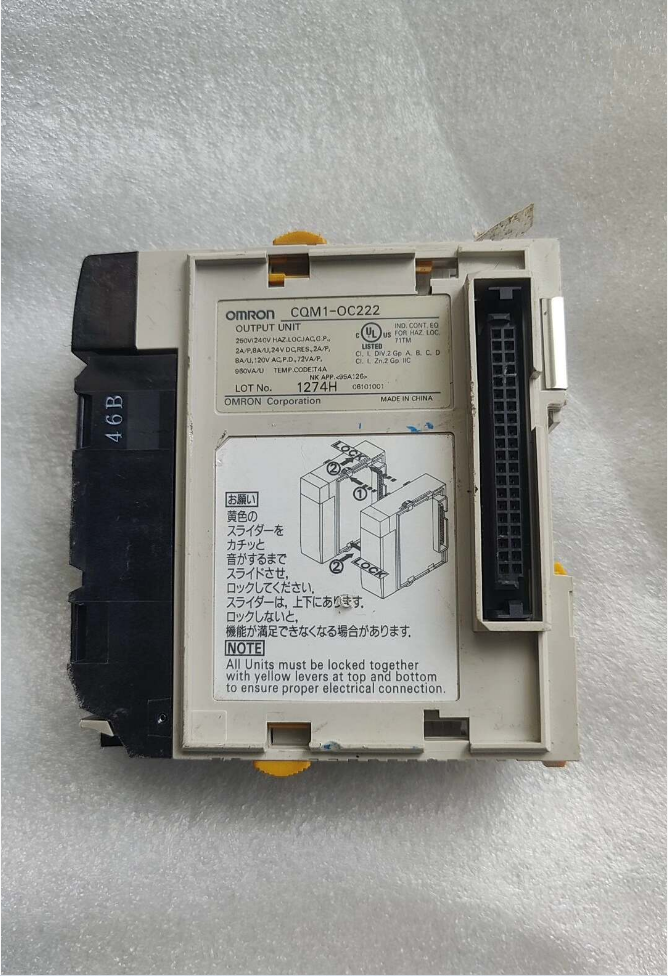

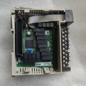
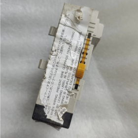
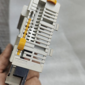
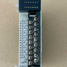
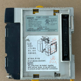
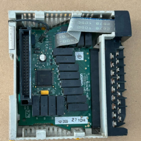
オムロン CQM1-OC222 Installation Instructions
⚠️Safety Precondition: Perform all installation work with power fully removed. Power off the PLC system and external load power. Hot-swapping modules is prohibited.
This is a CQM1/CQM1H-series I/O unit and works only on CQM1H backplane racks. Not compatible with CJ-series or CP-series racks.
シリーズ: CQM1 / CQM1H relay output module, 廃止, only second-hand or stock units available.
タイプ: Relay contact output, 16 ポイント, 2 common groups, 8 points per group (COM1: ポイント 0-7; COM2: ポイント 8-15).
コア仕様
| アイテム | パラメータ |
| 出力点数 | 16‑point relay output, 8 points per COM, 2 回路 |
| 負荷電圧 | AC250V; DC24V |
| Current per Point | 2A for resistive load; 0.5A for inductive load |
| マックス. Current per COM Group | 4あ (total for 8 ポイント); マックス. 8A for the whole module |
| Output Response | ON approx. 10 ms; OFF approx. 10 ms (relay mechanical delay) |
| 分離 | Relay opto‑isolation |
| 住所 | 占有します 1 I/O channel (16 bit) |
| Backplane Current Consumption | 5VDC: 130 ミリアンペア |
| 端子 | M3 screw terminal block |
>⚠️Notice: All points within one COM group must share the same external power supply. COM1 and COM2 may use different voltages. Independent power supply for each single point is not allowed. This differs from CQM1-OC221 (8-point independent COM).
モデルのデコード
CQM1: CQM1-series PLC I/O Unit
OC: Relay Contact Output
222: 16 ポイント, 2 common-group relay output
Comparison with peer-series modules:
CQM1-OC221: 8 ポイント, independent common terminal for each point, suitable for loads with different voltages per channel
CQM1-OC222: 16 ポイント, 2 common terminals, higher point density, shared power supply within each group
CQM1-OC224: New-version 8-point independent-COM unit
配線ガイドライン
- COM1 connects to external power common for outputs 0-7; COM2 connects to external power common for outputs 8-15.
- Relay outputs are dry contacts. The module provides no output power; external power must be supplied to loads.
- 誘導負荷の場合 (接触器コイル), install RC-snubber circuit / free-wheeling diode to extend relay contact service life.
- 端子締め付けトルク: 0.5 N・m.
交換オプション
Direct Compatibility with CQM1H Backplane (Direct Hardware Swap)
CQM1-OC222 is discontinued. No native 16-point 2-COM relay module in the same series.
Two pieces of CQM1-OC221: 合計 16 ポイント, but larger footprint, 8-point independent COM.
Upgrade to CJ-series (Backplane Incompatible; Full-PLC Upgrade Required)
CJ1W-OC211: 16-ポイントリレー出力, 2 COMグループ (8 points per COM). Closest electrical equivalent to CQM1-OC222. Program logic is portable, but it requires CJ1/CJ2 backplane and cannot plug directly into CQM1H rack.
Domestic Replacement Concept
Replace the whole PLC with Inovance H3U / H5U, paired with AM600-0016ER (16-ポイントリレー出力, 2 common terminals).
Second-hand Module Inspection Checklist for CQM1-OC222
- 目視チェック: Backplane connector without burn-off, terminal blocks without arcing blackening, no corrosion on housing.
- 電源投入テスト: Insert into CQM1H rack; confirm module is recognized without I/O errors.
- Forced-output via software: Force each point ON using CX-Programmer and observe panel LEDs. LED ON ≠ intact contact. (Healthy internal drive does not guarantee good relay contacts, a frequent failure for second-hand units.)
- Multimeter measurement: Measure continuity between output terminal and corresponding COM while forcing ON; verify infinite resistance in OFF state. Test all 16 points one-by-one.
- Typical failure modes:
LED ON but no continuity: Relay contact erosion (most common second-hand fault)
Total failure of 8-point group: Over-current burnout of COM circuit
Individual-point sticking: Output remains conductive even under OFF command
Common Troubleshooting Hints
- Relay mechanical service life is limited. Frequent switching of inductive loads accelerates contact erosion, sticking and poor contact.
- The module does not supply output power. Missing external load power may mimic “no output action”. Always check external power supply at COM terminals first.
- CQM1H CPUs all support CQM1-OC222. No CPU-version compatibility issue.
- 設置環境要件
- 周囲温度: 0 ~ 50 ℃. Ensure adequate ventilation inside control cabinet. Do not mount close to heaters or frequency converters.
- 湿度: 10%-85%RH, 結露なし. Keep away from dust, corrosive gas and oil mist.
- Avoid heavy vibration and strong electromagnetic interference sources (接触器, high-power inverters).
- Mount horizontally; do not install upside-down.
- Mounting Modules on Rack (Unit Assembly)
- Confirm PLC system is fully powered off.
- Align the left-side backplane connector of CQM1-OC222 with the right-side backplane interface of preceding unit (CPU, power supply or other I/O modules).
- Align modules and push horizontally until units fit tightly. Slide the upper and lower locking latches rearward all the way to lock adjacent units and guarantee reliable backplane contact.
- Install the End Cover at the far right end of the whole system and lock its latches. Missing end-cover causes I/O recognition failures.
- Mount the complete PLC assembly (電源 + CPU + I/Oモジュール) onto DIN35 rail: Press DIN-clip on module rear to snap onto rail. Release clip for removal.
注記: Physical slot position determines I/O channel address. No DIP-switches on module; addresses are automatically assigned by slot location.
- Terminal-Block Removal & フィッティング (Removable Terminal Block)
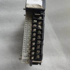
CQM1-OC222 adopts detachable M3-screw terminal block for convenient off-line wiring and module replacement without removing field cables.
- Remove terminal block: Pinch both side clips and pull straight out while module stays on rack.
- 配線後, align and push terminal block back into slot until both side clips click into locked position.
❗Do not pry forcibly to prevent clip breakage.
- Wiring Procedures & 仕様
端子トルク
M3ネジ, tightening torque 0.45-0.5 N·m. Over-torque damages threads; insufficient torque creates thermal loose-connection risks.
導体サイズ: 0.3-0.75 mm² (AWG22-18). Use solid wire or stranded wire with ferrules. Prevent stray copper strands from causing short-circuits.
Output Circuit Wiring Logic (致命的)
- COM1 terminal: Common for points 0-7; COM2 terminal: Common for points 8-15.
- This module provides relay dry contacts with no internal power source. Feed external power to COM terminals and connect loads to output-point terminals.
- COM1 and COM2 may accept different voltages (例えば. one group AC220V, another DC24V). Do NOT mix AC and DC within one COM group.
- 誘導負荷の場合 (接触器, 電磁弁): Apply RC-snubber for AC loads; reverse-parallel free-wheeling diode for DC loads to protect relay contacts.
Wiring Sequence
- Wire field load circuits first, then connect COM common power supply.
- Complete wiring, check for short-circuits and exposed copper strands.
- Confirm terminal-block is fully latched back onto module.
- Power-on & Hardware Verification
- Double-check PLC power and external load power are OFF; confirm right-hand end-cover is fitted.
- Switch on PLC system power and energize CPU. Observe module indicators:
No dedicated fault LED on this module under normal condition. Output LEDs follow internal output status.
- Go online via CX-Programmer. Confirm CPU recognizes the I/O unit and reports no I/O-unit error.
- Force each output point ON/OFF in software. Observe LED status and verify terminal continuity with multimeter to validate outputs.
- Module Replacement & Removal Procedure (メンテナンス)
- Power off PLC and cut external load power.
- Pull out removable terminal block (field wiring may remain on terminal block without disassembly).
- Unlock locking latches between this module and adjacent units.
- Gently pull module outward to disengage backplane connector and release from DIN rail.
- Install new module following above installation steps and re-insert terminal block.
- Common Installation Mistakes & Resulting Faults
- Missing right-hand End Cover: CPU fails to detect module; I/O error reported.
- Locking latches not fully engaged: Poor backplane contact; intermittent module dropout.
- Reversed COM-to-output-point wiring: Load inaction; mixed-voltage within one COM group → internal relay damage.
- Improper terminal screw torque: Overheating and arcing at terminals during operation.
- Hot-swap under power: Permanent burnout of backplane and module.
OMRON CQM1-OC222 Fault-Diagnosis Procedure
For relay-contact output units: LED ON does NOT guarantee intact relay contacts. Internal drive circuit can work normally while mechanical relay contacts are eroded or stuck (high-probability failure).
Before testing: Power off PLC and disconnect external power from module terminals to eliminate field-wiring interference.
- 目視検査 (Power-off State)
- Backplane connector: Check for burn-marks, 腐食, bent or damaged pins.
- Wiring terminals: Check for arcing blackening, scorch marks or melted plastic.
- ハウジング: Check for cracks, burn-damage and burnt odour.
Burn-marks or burnt smell usually indicate permanent hardware damage.
- Rack-mounted Power-on & Software Identification Test
Mount module into CQM1/CQM1H rack with end-cover fitted. Power-on and connect CX-Programmer.
- Verify whether hardware list correctly identifies CQM1-OC222.
- Check for I/O Unit Error / Unit Abnormal alarms.
✅Normal: Correct identification, no alarms. Backplane interface, onboard power and decoding circuits are basically functional.
❌Fault: Module not detected / unit error alarm:
Double-check end-cover and locking latches.
Test module in alternative slot; cross-test with known-good module.
If fault persists: Onboard main-board damage.
⚠️Successful recognition only proves circuit-board integrity. It does NOT guarantee healthy relay contacts. Many defective modules are recognized correctly but have bad individual-point contacts.
- LED Indicator Test (Software Forced Output)
Go online, force outputs ON/OFF and observe panel LEDs:
- LED illuminates upon FORCE-ON and extinguishes upon FORCE-OFF.
LED follows command: Internal drive transistor circuit works.
LEDが点灯しない: Internal drive circuit failure for that channel.
重要: Illuminated LED only means internal drive is activated. It does NOT guarantee relay-contact conduction! Multimeter terminal measurement is mandatory.
- Multimeter Test of Relay Contacts (Mandatory Key Step)
Disconnect all external field wiring. Set multimeter to continuity-beep / 抵抗モード.
Terminal mapping: COM1 for points 0-7; COM2 for points 8-15.
Test Steps
- Force point ON in software: Measure resistance between output terminal and its corresponding COM terminal.
✅Normal: Near-zero resistance, continuity beep.
❌Fault: 無限の抵抗 / no continuity → Relay-contact erosion (most frequent failure).
- Force point OFF in software: Measure resistance between output terminal and its corresponding COM terminal.
✅Normal: 無限の抵抗, no continuity.
❌Fault: Still conductive → Relay-contact sticking, uncontrolled load (hazardous fault).
Test all 16 points one-by-one. Often only 1-2 points fail while others remain functional.
Typical Fault Manifestations
- LED ON but no terminal continuity: Relay-contact erosion (top second-hand failure).
- LED OFF yet terminals remain conductive: Relay-contact sticking, output cannot be cut off.
- Complete failure of all 8 points under one COM: Over-current burnout of COM common circuit.
- Intermittent on-off for individual points: Oxidized contacts with unstable conduction.
- Distinguish Module Damage vs External-wiring Fault
Many symptoms are caused by field wiring rather than module failure. Follow this check sequence:
- Pull terminal block away from field cables and test module terminals standalone.
Fault persists after removing field cables → Module hardware failure.
All points pass standalone test; faults appear only after reconnecting field cables → Fault lies in external wiring or loads/power-supply.
- Quick Fault-Summary Table
| 現象 | Suspected Fault Location |
| PLC cannot detect module at all | Backplane or main‑board damage |
| LED does not follow program commands | Internal drive‑circuit damage |
| LED ON but no terminal continuity | Relay‑contact erosion (high‑frequency fault) |
| LED OFF but terminals stay conductive | Relay‑contact sticking |
| Intermittent action for individual points | Ageing / 酸化接点 |
| Complete 8‑point group failure | COM‑circuit burnout |
Supplementary Application Remarks
CQM1-OC222 relays have limited mechanical service life. Frequent switching of inductive loads such as contactors and solenoid valves accelerates contact wear. When purchasing second-hand units, perform full 16-point multimeter continuity test. Do NOT rely solely on LED status or PLC identification result.





NH42-63-318x560.png "CHINT PC型自動切替スイッチ (ATS)NH42-63/4SZ")



