 コンタクタ,サーキットブレーカー,センサー,エンコーダ,PLC,コンバータ

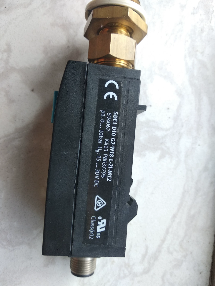

スタンダードモデルでは, 出力サフィックスは P1/P2/PI/N1/N2/NI です。 (デュアルPNPスイッチング出力). 完全な標準型番: SDE1-D10-G2-W18-L-P2-M12. It belongs to the discontinued SDE1-series relative-pressure sensor with LCD display.
モデルコードの内訳
| コード | 説明 |
| SDE1 | シリーズ: Pressure sensor with LCD display |
| D10 | 測定範囲: 0~10 bar relative pressure |
| G2 | 正確さ: ±2%FS |
| W18 | ポート & 取り付け: G1/8めねじ, wall‑mount bracket |
| L | 画面: Illuminated LCD with backlight |
| P2 | 出力: 2‑channel PNP switching output (‑21 in your input is a typo) |
| M12 | 電気接続: M12×1 4‑pin connector |
主要な技術仕様
Measuring medium: 濾過された圧縮空気 (lubricated / non-lubricated)
測定範囲: 0 … 10 bar; Overpressure rating: 20 bar
正確さ: ±2%FS; Repeatability: ±0.3%FS
電源電圧: DC 15-30 V, reverse-polarity protection
出力: 2×PNP switch, 最大. 150 mA per channel; configurable switch-point, hysteresis, window mode
Air port: G1/8
保護クラス: IP65
動作温度 (media & ambient): 0~50 ℃
重さ: 85 g
ハウジング: Reinforced PA+POM; CE, RoHS, UL certified
Pin Assignment M12-4-pin (male on sensor body)
| ピン | 信号 |
| 1 | DC24V Power positive |
| 2 | Switching output 1 (Out1) |
| 3 | 0V GND |
| 4 | Switching output 2 (Out2) |
Switch-output only, no analog output. Support Teach-in setting; PIN-code lock to prevent unintended parameter modification.
製品の状態
The whole SDE1 series is discontinued by パーティー. Only stock / used parts are available.
FESTO replacement series: SDE5. Same measuring range 0-10 bar, compatible mounting and air port. 参考モデル: SDE5-D10-O1-Q4-2P-M12.
一般的な障害点 (Used-unit Inspection)
- Blank LCD: Supply voltage below 15 V or internal electronics damage.
- 出力切り替えなし: Check Teach-in parameters and hysteresis setting; PNP output load ≤150 mA.
- 読み取りドリフト: Ensure no condensate in air supply; keep media temperature within 0-50 ℃.
- Air leakage: Damaged sealing of G1/8 thread.
Practical Application Cases for FESTO SDE1-D10-G2-W18-L-P2-M12 Pressure Sensor
Sensor features: 0-10 bar relative pressure, dual-PNP switching output, M12-4-pin, G1/8めねじ, wall-mount, backlit LCD, teach-in configuration. Mainly used for compressed-air monitoring. Dual-PNP channels support upperand lower-limit dual-threshold alarm: one channel for low-pressure alarm, the other for high-pressure alarm; or one for normal signal and one for fault alarm.
注記: SDE1 is discontinued. New projects adopt SDE5-D10-O1-Q4-2P-M12 as replacement.
Case 1: Main-air-supply Monitoring for Automation Equipment (assembly machines, トランスファーマシン)
作業条件
Wall-mounted SDE1-D10-G2-W18-L-P2-M12 installed downstream of the main FRL unit to monitor equipment air supply. 中くらい: filtered compressed air, nominal working pressure 5-7 bar.
パラメータ設定
Out1(PNP1): Lower-limit threshold 4.5 bar. Output ON below 4.5 bar for low-air-pressure alarm.
Out2(PNP2): Upper-limit threshold 7.5 bar. Output ON above 7.5 bar for high-air-pressure alarm.
制御ロジック
PLC reads two switching signals. アラーム & equipment inhibit when pressure is too low or too high. Equipment enable only if pressure stays within 4.5-7.5 bar.
価値
Avoid cylinder jamming / weak actuation caused by insufficient pressure; prevent damage to cylinders and valve islands by overpressure. Local backlit LCD for direct on-site pressure reading without upper-host communication.
互換性
W18 integrated wall-mount bracket fastens directly to cabinet sheet metal near valve islands. Vibration-resistant M12 connector for workshop environments. IP65 resists cutting-fluid splashes.
Case 2: Clamping-cylinder Pressure Monitoring in Packaging Machinery (case packers, case sealers, heat-sealing machines)
作業条件
Clamping mechanism of packaging machine. Cylinder target pressure 4-6 bar. Insufficient pressure fails to clamp cartons; excessive pressure damages products. Sensor fitted downstream of clamping-cylinder pressure-regulator.
パラメータ設定
Out1: Window lower limit 3.8 bar
Out2: Window upper limit 6.2 bar
Adopt window-comparator mode. Alarm trigger when pressure goes outside 3.8-6.2 bar.
プロセス
Clamping action is permitted only after sensor confirms valid pressure. Emergency stop and alarm upon pressure anomaly to avoid batch-product damage.
This unit provides only switch outputs, no analog signal. Suitable for pass/fail judgment without high-precision pressure acquisition.
Case 3: Fixture Tooling for Automotive-component Assembly (welding fixtures, press-fit tooling)
作業条件
Pneumatic press-fit tooling. Press-cylinder set-point ~6 bar. Low pressure causes incomplete press-fit; high pressure causes workpiece damage. Sensor mounted at regulator output of fixture.
パラメータ設定
Out1: <5.2 bar → low-pressure alarm
Out2: >6.8 bar → over-pressure alarm
論理
PLC receives sensor signals. Press-fit motion blocked and audible-visual alarm activated upon pressure fault. Operators read real-time pressure locally on LCD to adjust regulator without external pressure gauge.
On-site Features
Vibration-resistant M12 connection for tooling environment. Teach-in keys for quick on-site threshold adjustment. Password lock prevents unintended operator modification.
Case 4: Back-pressure Detection for Material-handling Suction Cups
知らせ: Measuring range 0-10 bar, cannot measure vacuum / negative pressure. Only for positive-pressure back-pressure detection, mostly for blow-type workpiece detection.
作業条件
Blow-type detection: Nozzle blows air toward workpiece. Pressure rises when workpiece blocks nozzle; pressure drops when no workpiece present.
パラメータ設定
Out1: Output ON when pressure>2 bar → workpiece detected
Out2: Spare channel, configurable for over-pressure protection
応用
Alternative to vacuum pressure switches for positive-pressure workpiece presence detection. Widely used in electronic-part sorting and injection-molded-part picking.
Case 5: Branch-line Pressure Monitoring for Air-treatment Units (マルチステーション機器)
作業条件
Independent pneumatic branches for transfer, clamping, lifting functions. One SDE1 sensor fitted on each branch after regulator.
論理
Dual-PNP outputs: one for pressure-loss alarm, one for over-pressure alarm. M12-wired to PLC digital-input modules for fast fault-location of faulty air branches and reduced troubleshooting time.
Case 6: Auxiliary Equipment for Injection-molding Machines (ロボット, material chutes, gate-cutting equipment)
作業条件
Pneumatic-circuit monitoring for injection-molding robots. Nominal working pressure of robot cylinders and grippers: 5-6 bar.
使用上の注意
IP65 against workshop dust and oil contamination. Backlit LCD guarantees readability under poor workshop lighting. Dual-switch outputs realize both low-pressure and over-pressure protection.
アプリケーションの制限 & Practical Pitfalls
- Only measures positive relative pressure 0-10 bar; vacuum measurement not supported. Select SDE1-V1 (-1~0 bar) variant for vacuum applications.
- Dual-PNP switch outputs only, no analog output. Choose -PI /-PU suffix for 4-20 mA / 0-10 V analog signal.
- Medium restricted to filtered compressed air. Not for water or hydraulic oil. Condensate in compressed air will damage sensor.
- W18 stands for wall-mount installation, not DIN-rail mounting. Select -H18 suffix for DIN-rail mounting.
- Discontinued product; only stock / used spare parts available. Replacement SDE5-D10-O1-Q4-2P-M12 with largely compatible installation and functions.
Complete Parameter-setting Manual for FESTO SDE1-D10-G2-W18-L-P2-M12
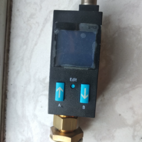
Key-button description:
EDIT: 確認する / enter menu
あ (上): OutA Channel 1, value increment
B (Down): OutB Channel 2, value decrement
RUN mode: Power-on default, displays real-time pressure; long-press EDIT for 3 s to return to RUN at any time.
Four operation modes:
- 走る: 手術, real-time-pressure display
- SHOW: Parameter review (read-only)
- EDIT: Parameter editing (threshold, mode, ユニット, password)
- TEACH: Teach-in, capture current pressure as switch-point
P2 model: OutA = Channel 1; OutB = Channel 2, dual-PNP output. Factory default: threshold comparator, NO normally-open, hysteresis HY=0.2 bar (2%FS), unit bar, password lock disabled.
- Pre-configuration Preparation
- Supply DC24 V, connect air supply. Sensor enters RUN mode and shows real-time pressure.
- Flashing `Lock` on display: password lock activated. Password input required before modification. Direct-access to EDIT if unlocked.
- M12 connector tightening torque: 0.5 Nm. Do not over-tighten G1/8 thread.
- Enter EDIT Edit Mode
- Under RUN mode, short-press EDIT. Display flashes `OutA` (Channel 1 selected).
- Press B to switch to `OutB` for Channel 2 setup.
- Short-press EDIT again to enter parameter editing for selected channel.
- Short-press EDIT to confirm each item and jump to next parameter.
- Long-press EDIT for 3 seconds to save all parameters and return to RUN.
Each channel can be independently configured: 動作モード, switch-point, hysteresis HY, NO/NC normally-open / normally-closed.
Two Output Operation Modes
- Threshold comparator _|¯ (single set-point SP)
いいえ: Output PNP ON when pressure>SP; OFF when pressure<SP-HY.
ノースカロライナ州: Output PNP ON when pressure<SP-HY; OFF when pressure>SP.
- Window comparator _|¯|_ (SPmin lower limit, SPmax upper limit)
いいえ: Output ON when pressure is between SPmin~SPmax; OFF outside range.
ノースカロライナ州: Output ON when pressure is outside SPmin~SPmax; OFF inside range.
Typical usage:
Upper-lower-limit alarm: OutA for low-pressure alarm (threshold comparator NO); OutB for high-pressure alarm (threshold comparator NO).
Qualified-range detection: Single-channel window comparator, output ON when pressure stays within valid range.
- Method A: Manual Numeric Entry (推奨)
Sample requirement:
OutA (Channel 1): Alarm below 4.5 bar; threshold comparator, いいえ, HY=0.3 bar
OutB (Channel 2): Alarm above 7.5 bar; threshold comparator, いいえ, HY=0.3 bar
Configure OutA (Low-pressure Alarm)
- RUN → short-press EDIT, flashing `OutA`, press EDIT to enter.
- Select mode `_|¯` threshold comparator, confirm with EDIT.
- Set SP switch-point to 4.5 bar, confirm with EDIT.
- Set HY hysteresis to 0.3 bar, confirm with EDIT.
- Select NO normally-open, confirm with EDIT.
Configure OutB (High-pressure Alarm)
- Return to EDIT top menu, press B to switch to `OutB`, press EDIT to enter.
- Select mode `_|¯` threshold comparator, confirm with EDIT.
- Set SP switch-point to 7.5 bar, confirm with EDIT.
- Set HY hysteresis to 0.3 bar, confirm with EDIT.
- Select NO normally-open, confirm with EDIT.
- Long-press EDIT for 3 s to return to RUN. Parameters take effect.
Window-mode procedure: 選択 , then configure SPmin, SPmax, HY, NO/NC sequentially.
- Method B: TEACH-IN Teach-in Calibration (Fast On-site Setup)
Capture actual pipeline pressure as switch-point without manual numeric input.
- RUN mode, adjust air-supply pressure to desired switch-point TP1.
- Simultaneously press【A + EDIT】. Current pressure is saved as TP1 for selected channel.
- Adjust air-supply pressure to second target TP2, press【A + EDIT】again to save TP2.
Threshold-comparator mode: SP is calculated as mid-value between TP1 and TP2.
Window-comparator mode: TP1 = SPmin, TP2 = SPmax.
- Long-press EDIT to return to RUN.
For OutB teach-in: Use【B + EDIT】key combination.
- Unit Setting & Password Lock
- Short-press EDIT under RUN mode. Scroll with A/B keys to find `Lock`.
- Press EDIT to enter sub-menu:
Unit selection: バー / kPa / psi; bar preferred for industrial applications.
Password lock: 0 = lock off; 1-9 = lock enabled. Password required before entering EDIT.
When password lock is enabled, `Lock` flashes upon entering EDIT. Input password with A/B keys and confirm with EDIT to unlock.
Forgotten password: 工場出荷時の設定を復元する.
- SHOW Mode: パラメータのレビュー (Read-only)
Under RUN mode:
Press A: Scroll through OutA parameters: mode, SP, HY, いいえ/いいえ
Press B: Scroll through OutB parameters: mode, SP, HY, いいえ/いいえ
Press A+B simultaneously: View max/ min-pressure values; long-press A+B for 2 s to clear peak-value records.
- Restore Factory Settings
電源を切る; hold A+B pressed, power on, keep holding and press EDIT. Display flashes for several seconds. All custom parameters reset and password cleared.
⚠️ All user-configured parameters will be lost. Operate with caution.
- Common Commissioning Troubleshooting
- 出力信号なし
Verify NO/NC configuration; check relation between SP threshold and actual pressure; PNP output load ≤150 mA; confirm 24 V supply.
- Frequent output chattering: Increase hysteresis HY, 例えば. from 0.2 bar to 0.3-0.5 bar. Mandatory for fluctuating air supply.
- Parameter modification forbidden: `Lock` flashing. Unlock by password input or restore factory settings.
- Inverted alarm logic: Toggle NO (normally-open) ↔ NC (normally-closed).
- Reference Engineering Configuration (Air-supply Monitoring)
| チャネル | モード | HY | いいえ/いいえ | 説明 | |
| OutA | Threshold | 4.5 bar | 0.3 bar | いいえ | Output OFF below 4.5 bar; ON above 4.5 bar; low‑pressure alarm triggered below 4.2 bar |
| OutB | Threshold | 7.5 bar | 0.3 bar | いいえ | Output ON above 7.5 bar; over‑pressure alarm triggered above 7.8 bar |
PLCロジック: OutA = 0 → low-pressure alarm; OutB = 1 → over-pressure alarm.
- Notice for Replacement Model SDE5
SDE5 menu structure differs. SDE1 key-operation procedure cannot be applied directly. SDE1 is discontinued; use stock spare-parts only.





NH42-63-318x560.png "CHINT PC型自動切替スイッチ (ATS)NH42-63/4SZ")



