 コンタクタ,サーキットブレーカー,センサー,エンコーダ,PLC,コンバータ

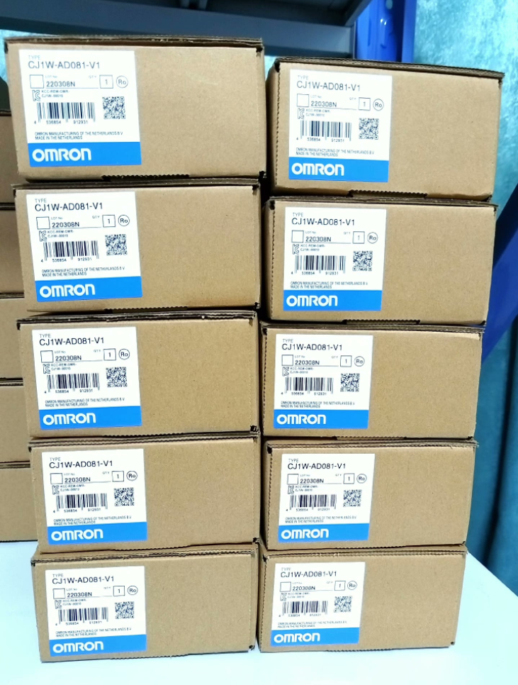

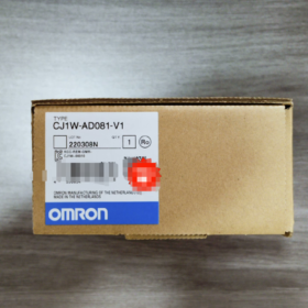
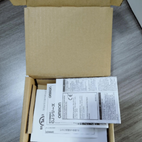
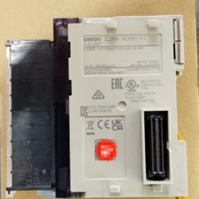
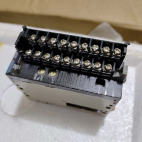
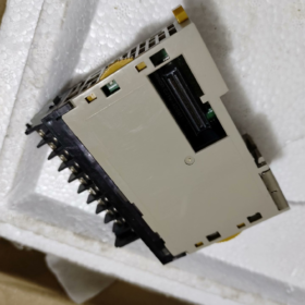
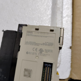
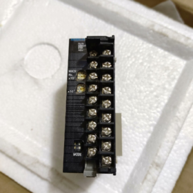
CJ1W-AD081-V1
- CJ1W: Special I/O module series base for CJ1-series PLCs
- 広告: アナログ入力
- 08: 8 アナログ入力チャンネル
- 1: Standard hardware revision
- V1: Upgraded functional version (supports wire break detection, dual resolution switching, and digital smoothing filter)
Derivative Model: CJ1W-AD081-V1-SL (spring screwless terminal type)
- コアハードウェア仕様
基本パラメータ
| アイテム | 仕様 |
| チャンネル数 | 8 independent analog inputs (CH1~CH8) |
| Compatible PLC CPUs | Full lineup of CJ1M / CJ1H / CJ2M / CJ2H CPUs |
| バスインターフェース | Dedicated CJ backplane I/O bus; 外部電源は不要です |
| Backplane Power Consumption | DC 5V ≤ 420mA |
| Isolation Scheme | Optocoupler isolation between internal module circuit and PLC bus; no isolation between individual channels |
| 全体の寸法 | W31mm × H90mm × D65mm |
| 重さ | ≤ 140g |
| 動作環境 | 0~55℃, 10%~90% RH non-condensing |
| 端子仕様 | スタンダードモデル: M3ネジ端子; SL model: spring quick-disconnect terminals, 18-pin detachable terminal block |
Input Signal Ranges (Hardware DIP switch selectable per channel)
電圧入力 (DIP Switch = OFF)
-10~+10V, 0~10V, 0~5V, 1~5V
入力インピーダンス: ≧1MΩ, Maximum Withstand Voltage: ±15V
電流入力 (DIP Switch = ON, built-in 250Ω sampling resistor)
4~20mA, 0~20mA
入力インピーダンス: 250おお, Maximum Withstand Current: ±30mA
Conversion Accuracy & 解決
- Two software-selectable resolution grades
4000-count (12-少し): Economical mode with fast conversion speed
8000-count (13-少し): High-precision mode for precise flow/pressure measurement
- Full-scale Accuracy (周囲温度: 25℃)
電圧入力: ±0.2%FS
電流入力: ±0.4% FS
- Full-temperature Range Accuracy (0~55℃)
電圧信号: ±0.4% FS
電流信号: ±0.6% FS
- 変換速度: 1チャネルあたりのミリ秒; full scan of 8 channels takes 8ms; high-speed mode: 250チャネルあたりのμs
- Built-in Core Functions
- Wire Break Detection (Dedicated for 4~20mA Circuits)
When a current loop is open, the corresponding channel wire break flag turns ON for program-based alarming.
- Digital Smoothing Filter
Average value calculation to suppress sensor jitter and on-site electromagnetic interference.
- ピーク / Valley Hold
Captures and locks the maximum and minimum analog values within a cycle, suitable for impact pressure and instantaneous flow acquisition.
- Offset / Gain Calibration
Onboard calibration registers allow on-site correction of sensor zero drift.
- Custom Range Scaling
Upper and lower limits of ±32000 can be configured to directly map 4–20mA signals to engineering values such as 0~1000 or 0~5000.
- 端子配線の定義 (18-Pin Terminal Block)
Each channel occupies two terminals: V+ (シグナルポジティブ), COM (Common Negative)
CH1: ピン1(V+), Pin2(COM)
CH2: ピン3(V+), Pin4(COM)
CH3: Pin5(V+), Pin6(COM)
CH4: Pin7(V+), ピン8(COM)
CH5: Pin9(V+), Pin10(COM)
CH6: Pin11(V+), Pin12(COM)
CH7: Pin13(V+), Pin14(COM)
CH8: Pin15(V+), Pin16(COM)
Pin17, Pin18: Shield grounding terminals (Connect all sensor shield cables here for anti-interference performance)
配線ガイドライン
- Voltage signals: Connect only V+ and COM; set DIP switch to OFF
- 2-wire 4~20mA transmitters: Connect V+ to transmitter positive terminal, COM to 24V negative terminal; set DIP switch to ON
- It is recommended to common the COM terminals of multiple sensors. Connect shield layers to pins 17/18 of the module at one end only; double-end grounding is prohibited.
- PLC Memory Allocation (Special I/O Unit)
- Input Relay Area (10 Words): Stores raw A/D conversion values for 8 チャンネル
CH1: Channel Word 0; CH2: Channel Word 1 … CH8: Channel Word 7
- Output Relay Area (10 Words): Function setting registers
Includes resolution switching, filter sampling count, wire break detection enable, upper/lower scaling limit parameters
- 設定ソフトウェア: CXプログラマー + CXインテグレーター. Channel addresses are automatically assigned after registering the module in the I/O table.
- Typical Industrial Application Scenarios
- Fluid Control: Acquisition of 4–20mA transmitters for pressure, liquid level and flow
- Temperature Control Systems: 0~10V / 1~5V temperature transmitter modules
- Analog Feedback for Inverters & サーボドライブ: Collection of 0~10V speed and torque feedback signals
- Centralized multi-point analog signal acquisition for water treatment, chemical and packaging machinery
- 同じシリーズの比較 & 代替ソリューション
Comparison of Analog Input Modules in the Same Series
| モデル | チャンネル数 | 主な特長 |
| CJ1W-AD041-V1 | 4 チャンネル | Low-cost solution for small-scale point acquisition |
| CJ1W-AD081-V1 | 8 チャンネル | Standard general-purpose model with largest market stock |
| CJ1W-AD161 | 16 チャンネル | High-density acquisition; without V1 enhanced functions |
アップグレード & Compatible Replacements
- Direct drop-in replacement on the same platform: CJ1W-AD081-V1-SL (スプリング端子, identical hardware parameters; no program modification required)
- CJ2 Series Compatibility: Direct mounting on CJ2M/CJ2H CPUs with unchanged I/O configuration
- Replacement for legacy CS Series: CS1W-AD081-V1 (Backplanes are incompatible; CPU rack replacement is mandatory)
- New-generation NX Series Alternative (Recommended for new projects): NX-AD4208 (8-チャンネルアナログ入力, EtherCATバス)
- 一般的な障害のトラブルシューティング マトリックス
| 故障現象 | Root Causes | 解決手順 |
| All channels show fixed zero value | 1. Module not registered in CX-Integrator; 2. Poor backplane contact; 3. Insufficient 5V backplane power supply | 1. Rebuild and download the I/O table; 2. Remove and re-seat the module firmly; 3. Reduce the number of modules installed on the backplane |
| Single channel value unchanged / stuck at full scale | 1. Incorrect DIP switch setting for voltage/current mode; 2. Open/short circuit in signal wiring; 3. Loss of 24V power supply to transmitter | 1. Verify channel DIP switch configuration; 2. Test circuit continuity with a multimeter; 3. Check power supply to sensors |
| Frequent wire break alarms on 4–20mA channels | 1. Excessive voltage drop along cables; 2. Insufficient load capacity of transmitters; 3. Loose terminal connections | 1. Use thicker signal cables; 2. Shorten cable length; 3. 端子ネジを締める |
| Severe signal drift and fluctuation | 1. Shield ground not connected; 2. Smoothing filter disabled; 3. Analog cables laid in parallel with power cables inside the same trunking | 1. Connect shield wires to module ground terminals; 2. Enable average filter in software; 3. Separate low-signal wiring and high-power wiring |
| 過剰な変換エラー | 1. Ambient temperature exceeds 55°C; 2. Long-term zero drift; 3. External signals out of rated range | 1. Improve cooling of control cabinet; 2. Perform offset/gain calibration; 3. Confirm matching of transmitter measuring range |
- 使用制限 (Strictly Forbidden Operations)
- Do not set DIP switches of voltage-input channels to current mode; this will burn the internal sampling resistor of the module
- Never apply input signals exceeding ±15V (voltage mode) or ±30mA (current mode); A/D chips may suffer permanent breakdown
- Avoid parallel routing of analog signal cables with power cables for inverters and contactors in the same cable trunking; severe electromagnetic interference will cause data distortion
- Double-end grounding of transmitter shield layers is prohibited, as circulating current will introduce power-frequency interference
- Power off the entire PLC system before plugging/unplugging modules; hot swapping will damage backplane bus interfaces
Official Accuracy Specifications of CJ1W-AD081-V1 (Per OMRON Manual Standards)
- Nominal Accuracy at Room Temperature (23±2°C / 25℃, Full-Scale Error)
- 電圧入力 (0~5V / 0~10V / -10~+10V / 1~5V)
Overall Accuracy: ±0.2%FS
- 電流入力 (4~20mA / 0~20mA)
Overall Accuracy: ±0.4% FS
> 注記: FS = Full Scale, referring to relative error across the entire signal range, including integrated zero-point, gain and linearity errors.
- Full-Temperature Range Accuracy (0~55°C Operating Temperature)
Voltage Signals: ±0.4% FS
Current Signals: ±0.6% FS
- 解決 (Distinction Between “正確さ” そして “解決”)
Resolution refers to the minimum detectable signal change and is not equivalent to accuracy:
- Low-speed mode (1チャネルあたりのミリ秒): 1/4000 (12-少し)
- 高速モード (250チャネルあたりのμs): 1/8000 (13-少し)
Error Calculation Examples
Calculation based on 4~20mA (full span = 16mA) with current accuracy ±0.4%FS:
Maximum Absolute Error = 16mA × 0.4% = ±0.064mA
Calculation based on 0~10V voltage with accuracy ±0.2%FS:
Maximum Absolute Error = 10V × 0.2% = ±0.02V
- Supplementary Remarks
- Factory default calibration is optimized for voltage signals. For 4–20mA current loop applications, perform offset/gain calibration via software to further reduce current measurement errors.
- No galvanic isolation exists between channels. Additional measurement errors may be introduced by multi-sensor common-ground wiring, long cables or heavy electromagnetic interference; such errors are not included in the module’s nominal accuracy rating.
- The specified accuracy excludes external error sources such as sensor intrinsic error, cable voltage drop and grounding interference.
Full Application Scenarios of CJ1W-AD081-V1 (Classified by Industry, Equipment and Collected Signals)
This is a general-purpose 8-channel analog acquisition module compatible with 4~20mA / 0~10V / 1~5V signals, equipped with wire break detection, digital filtering and peak hold functions. It supports CJ1H/CJ1M/CJ2M/CJ2H CPUs and is ideal for multi-point continuous physical quantity collection, closed-loop process control and equipment condition monitoring. No isolation between channels, making it suitable for sensor networks sharing a common ground at the same location.
- 化学薬品 / 水処理 / 環境保護 (Most Common Application Field)
Collected Signals
Mainly 4~20mA 2-wire transmitters: liquid level, pipeline pressure, 流量, PH/ORP, dissolved oxygen, turbidity, chemical reagent concentration, reactor temperature
装置 & システム
- Complete wastewater treatment equipment: Closed-loop dosing control based on biochemical tank liquid level, aeration pressure, influent and effluent flow rates, and chemical tank liquid level
- Pure water / reverse osmosis equipment: Collection of product water flow, pre/post-membrane differential pressure and conductivity transmitter signals
- Chemical reactors / mixing kettles: Interlocked temperature and pressure control based on kettle temperature, internal pressure and raw material feed flow
- Exhaust gas treatment / desulfurization & 脱窒: Monitoring of flue gas temperature, 差圧, reagent flow and acid-base neutralization concentration
Module Advantages
4~20mA wire break detection: Automatic alarm for broken cables or power loss of transmitters
Digital filtering eliminates power-frequency interference from water pumps and fans
8 channels enable simultaneous acquisition of multiple tank and pipeline measuring points to reduce total module quantity
- 食べ物 & 飲料 / 医薬品 / Ready Meal Production Lines
Collected Signals
Temperature transmitters (PT100 converted to 4~20mA), tank liquid level, syrup/material flow, filling pressure, vacuum degree
装置
- Sterilizing kettles, cooking pots: Closed-loop multi-point temperature control with interlock shutdown for overtemperature
- Batching and mixing systems: Automatic feeding based on raw material tank level and delivery flow ratio
- Filling and blow molding equipment: Collection of filling pressure and negative vacuum to guarantee filling precision
- Pharmaceutical purified water and mixing tanks: Compliant data logging of liquid level, temperature and differential pressure (GMP traceability)
Matching Strengths
±0.2% FS high precision at room temperature meets process metering requirements; peak hold captures instantaneous pressure fluctuations.
- 包装 / 印刷 / ゴム & Plastics Machinery
Collected Signals
Predominantly 0~10V voltage signals: Servo/inverter speed feedback, tension sensors, mold cavity pressure, melt extrusion pressure
装置
- 垂直 / horizontal packaging machines: Film roll tension and heat-seal temperature acquisition for constant-tension closed-loop control
- 射出成形 / 押出機: Segmented barrel temperature, melt pressure and hydraulic system oil pressure
- Printing machines: Roller pressing pressure and ink concentration transmitter signals
- Blow molding and bag-making equipment: Mold temperature and air supply pressure monitoring
マッチングのメリット
High-speed 250μs per channel conversion captures rapidly varying tension and pressure; centralized multi-channel acquisition of all analog feedback signals from the whole machine.
- 空調設備, ビルディングオートメーション & セントラル空調
Collected Signals
温度 & humidity transmitters (4~20mA), air duct differential pressure, cold/hot water flow, chilled water pressure, CO₂ concentration
システム
Factory central air conditioning, cleanroom air handlers, 一定の温度 & humidity units for dust-free workshops, fresh air & 排気システム
Application Purpose
Automatically adjust fan speed and chilled water valve opening based on indoor temperature, humidity and CO₂ concentration for energy-saving coordinated control.
- エネルギー, 太陽光発電, ウォーターポンプ & Fan Stations
Collected Signals
Battery temperature, solar irradiance intensity, pump outlet pressure, water tank liquid level, motor bearing temperature
Scenarios
- PV energy storage cabinets: Multi-point temperature measurement of ambient environment and battery packs
- Constant-pressure water supply pump rooms: Closed-loop variable-frequency constant pressure control via pipeline pressure acquisition
- Air compressor stations: Monitoring and early warning of air tank pressure, exhaust temperature and lubricant oil temperature
- Boiler auxiliary equipment: Feed water flow, furnace negative pressure and flue gas exhaust temperature
- 工作機械, 自動生産ライン & Custom Non-Standard Equipment
Collected Signals
Hydraulic oil pressure, cylinder pressure, cutting fluid temperature, 0~10V displacement sensors, vibration transmitters
装置
CNC旋盤, 組立ライン, stamping equipment, automated test fixtures
コア機能
Equipment condition early warning with automatic shutdown for excessively low oil pressure or high temperature; dimensional inspection via displacement signal collection.
- Agriculture, 水の保全 & Aquaculture
- Aquaculture: Automatic aeration and water exchange interlock based on water dissolved oxygen, water temperature and pond liquid level
- 灌漑 & water conservancy: Automatic irrigation control via collection of pipeline flow, pool liquid level and soil humidity transmitter signals
推奨されないアプリケーション シナリオ (モデル選択の落とし穴の回避)
- Demand for strong isolation between multiple channels: Only the bus side features optocoupler isolation with no inter-channel isolation. For sites with multi-sensor separate grounding or severe interference, prioritize CJ1W-AD041-V2 (channel-isolated model).
- Control cabinets with high voltage and intense electromagnetic fields or dense inverters: External signal isolators must be installed to prevent severe signal drift.
- Less than 4 analog measuring points: Select CJ1W-AD041-V1 for lower cost; choose CJ1W-AD161 for high-density 16-point acquisition.
Application Value Corresponding to Core Module Functions
- Wire Break Detection → Prevents circuit faults for 4–20mA transmitters in water treatment and chemical industries
- Digital Average Filter → Anti-interference for on-site water pumps, fans and inverters
- ピーク / Valley Hold → Recording of injection melt pressure and instantaneous stamping pressure
- Offset & Gain Calibration → Corrects long-term sensor zero drift to sustain consistent measurement accuracy
- 8-Channel Mixed Signal Compatibility → Supports mixed wiring of voltage and current transmitters on a single module to reduce cabinet module count





NH42-63-318x560.png "CHINT PC型自動切替スイッチ (ATS)NH42-63/4SZ")



