 コンタクタ,サーキットブレーカー,センサー,エンコーダ,PLC,コンバータ

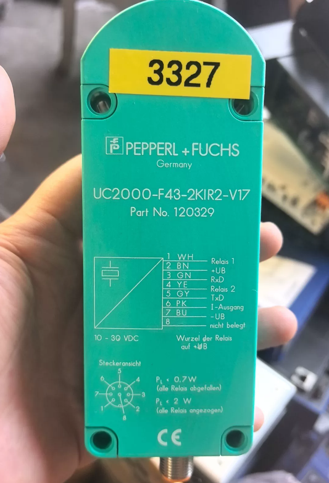

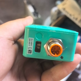
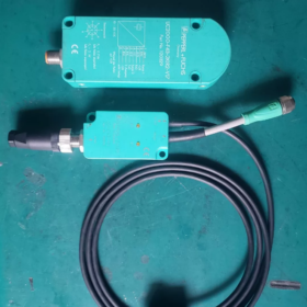
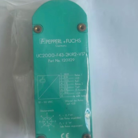
Official Part No.: 120329 状態: 製造中止
製品タイプ: Rectangular Ultrasonic Distance Sensor (Single Transceiver)
- 型式コードの説明
UC2000: シリーズ, maximum sensing distance 2000 mm
F43: Rectangular housing, fixed sound emission angle structure
2KIR2: 2 relay contact outputs + 4…20 mA analog current output
V17: M12×1, 8-pin male connector
- 主要な技術仕様
Sensing Performance
Blind zone: 0~80 mm
Adjustable effective range: 100~2000 mm
Total detection range: 80~2000 mm
Ultrasonic frequency: 約. 175 kHz
Measurement resolution: 0.6 mm
Repeat accuracy: ≤0.1 % of full scale
Linearity error: <0.2 % of full scale
Standard target plate: 100×100 mm flat surface
応答時間: minimum 50 MS; 工場出荷時のデフォルト 150 MS
電気仕様
供給電圧
Relay operation only: 10~30 VDC
With 4–20 mA analog output activated: 15~30 VDC
No-load power consumption: ≤0.7 W; maximum load ≤2 W
出力構成:
- Two passive relay contacts (単極, 最大. 60 VDC / 1 あ, 抵抗負荷 24 W)
- One 4–20 mA analog distance signal
コミュニケーション: Built-in RS232 (9600,8N1). Parameters configured via ULTRA 2001 / ULTRA3000 software plus UC-PROG1-USB programming cable
保護: 逆極性保護, 温度補償
機械式 & 環境仕様
ハウジング材質: PBT thermoplastic
保護クラス: IP65
動作温度: -25 ℃ … +70 ℃
保管温度: -40 ℃ … +85 ℃
重さ: 約. 290 g
インタフェース: M12 8-pin male connector (V17)
- M12 8-Pin Pin Assignment (V17)
| ピン | 指定 | 説明 |
| 1 | UB+ | Positive supply voltage |
| 2 | リレー 1 COM | Common terminal for Relay 1 |
| 3 | UB- / GND | Negative supply voltage / Ground |
| 4 | リレー 1 いいえ | Normally Open contact of Relay 1 |
| 5 | リレー 2 COM | Common terminal for Relay 2 |
| 6 | リレー 2 いいえ | Normally Open contact of Relay 2 |
| 7 | 4…20mA IOUT | Analog current output |
| 8 | シールド / RS232 GND | Cable shield, serial communication ground |
> Relays are factory-set as Normally Open. Switching points, hysteresis (0~15%) and measuring window can all be modified via software.
- LED Indicator Definition
Green LED steady ON: Target within configured measuring window
Green LED flashing: Target outside measuring window
Red LED illuminated: Fault condition (no echo signal, excessive interference, communication error)
- 典型的なアプリケーションシナリオ
Material level monitoring, stack height detection, warehouse goods distance measurement, object positioning on conveyor lines, non-contact liquid level measurement.
Ideal for applications requiring two independent threshold switch signals + continuous analog distance signal simultaneously.
- 重要な注意事項 & 交換オプション
- このモデルは生産終了です. No original factory supply available; only surplus stock / used units exist on the market. Not recommended for new projects.
- アップグレードの代替案:
Preferred modern equivalent: UC2000-F43-IU-V15 (IO-Link version, replaces RS232; supports 4–20mA, transistor switching outputs. External relay modules required if relay contacts are needed)
If relay output is mandatory: Consult Pepperl+Fuchs authorized distributors for compatible alternative models.
- Mandatory Programming Accessories: UC-PROG1-USB programming adapter + ULTRA3000 configuration software. Ordinary serial cables cannot be used for parameter setup.
Practical Application Cases of Pepperl+Fuchs UC2000-F43-2KIR2-V17
Core unique advantages of this model: Rectangular F43 housing, 最大 2 m measuring range, dual passive relay contacts + synchronous 4~20mA analog output, built-in RS232 software configuration.
Perfect for legacy equipment retrofits, installations where the PLC lacks spare transistor inputs, and systems requiring continuous measurement plus hard-contact alarm signals at two threshold levels.
場合 1: Chemical Dosing Tank Level Monitoring (Classic Legacy Project)
動作要件
PAC/PAM chemical plastic tanks in water treatment plants, maximum tank height 1.8 メートル.
- Continuous liquid level signal transmitted to central control PLC via 4~20mA for real-time level display on HMI;
- Two independent passive switch signals: low liquid level (reagent shortage alarm) and high liquid level (overflow prevention) to directly drive audible & visual alarms without additional intermediate relays;
- Mild water vapor exists inside tanks; photoelectric sensors are prone to failure; contact-type float switches cannot be used due to corrosive media.
実装
UC2000-F43 mounted vertically on tank roof, measuring window set to 120~1900 mm;
リレー 1 configured for high-level overflow pre-alarm, リレー 2 configured for low-level reagent shortage alarm;
4~20mA signal connected to analog input module for liquid level conversion;
Use ULTRA3000 software to adjust false echo suppression to adapt to minor liquid surface fluctuations.
Reason for Selection
Dual passive relay contacts can directly operate 24V alarm lights; no extra intermediate relays required in legacy control cabinets. Rectangular housing facilitates mounting with tank roof brackets. Compared with transistor-output sensors, contact status is maintained after power failure.
> 制限: Not suitable for liquids with heavy surface foam, which will cause loss of echo signals.
場合 2: Pallet Stack Height Detection on Conveyors & 自動倉庫
動作要件
Finished goods conveyor system; detect stacking height of goods on pallets (max height 1.9 メートル).
- Continuous height measurement sent to control system to judge overheight condition;
- Two threshold settings: height warning limit (conveyor speed reduction) and overheight limit (inbound interlock stop);
- Outdated control cabinets with traditional relay circuits, limited spare PNP/NPN digital input points.
実装
Sensor overhead mounted vertically above conveyor to detect goods on pallets;
4~20mA outputs continuous height data;
Relay1 = warning height (reduce conveyor speed); Relay2 = overheight threshold (trigger safety stop interlock).
マッチングのメリット
Measurement unaffected by goods color or carton surface reflection. Passive relay contacts can be directly wired into existing safety relay circuits, minimizing drawing modification and construction workload during retrofit.
場合 3: Dancer Roller Position Monitoring on Paper & Film Production Lines
動作要件
Floating dancer roller for tension control during winding/unwinding of paper or plastic film; roller travel range 0~1800 mm.
- 4~20mA analog signal sent to variable frequency drive to adjust winding speed and maintain stable web tension;
- Two relay outputs: upper roller limit (web break protection) and lower roller limit (raw material depletion stop).
実装
Sensor horizontally mounted aiming at a flat metal baffle fitted to the dancer roller; response time adjusted to 100 ms via software to suppress minor oscillation.
Selection Highlight
Photoelectric sensors easily get contaminated by paper dust and mist; ultrasonic sensors offer strong resistance to dust. A single sensor delivers continuous regulation signal + limit safety contacts, performing both tension closed-loop control and equipment protection.
場合 4: Material Level Monitoring on Crusher Feed Hoppers for Waste Processing Equipment
動作要件
Monitor filling height of raw material inside crusher feed hoppers; prevent no-load operation and material overflow. Harsh environment with heavy dust, strong vibration and wide temperature variation (-20~+60℃).
- 4~20mA signal uploaded to supervisory system for material feeding statistics;
- High level: stop feeding belt conveyor; low level: start feeding conveyor.
実装
Sensor obliquely installed to avoid hopper wall interference; temperature compensation enabled in software; two relays control belt start/stop circuits.
利点
IP65 dust and water resistance, 広い動作温度範囲. Relay contacts withstand field voltage fluctuations better than transistor outputs and are less vulnerable to induced voltage damage.
場合 5: Lifting Position Monitoring of Automatic Electroplating Cranes
動作要件
Automatic electroplating crane; measure descent distance of lifting frame to control workpiece immersion depth in chemical solution; travel range 0~1.7 m. High humidity and corrosive acid mist inside workshop.
- 4~20mA feedback of lifting frame height in real time;
- Lower limit contact: stop downward movement upon arrival; upper limit contact: overtravel anti-crash protection.
予防
Avoid direct steam blowing onto transducer surface; install rain & splash shield; periodically verify measurement offset using ULTRA3000 software.
General Selection & 試運転メモ (For This Discontinued Model)
- Blind zone = 80 mm, minimum effective starting measurement distance 100 mm; sufficient clearance must be reserved during design.
- Maximum relay contact load: 60 VDC / 1 あ. Never directly drive high-power motors.
- When using the 4~20mA analog output, supply voltage must be ≥15 VDC. 12 VDC supply will cause abnormal analog readings.
- UC2000-F43-2KIR2-V17 is discontinued. Plan replacement models in advance for new projects.
Preferred alternative: UC2000-F43-IU-V15 (IOリンク + 4-20mA transistor output; external relays required if contact outputs are needed).
- If multiple sensors are installed side-by-side, enable synchronization function via software to prevent mutual ultrasonic interference.
Complete Installation Guide for Pepperl+Fuchs UC2000-F43-2KIR2-V17
> Key Predefined Parameters: Blind zone 0~80 mm, effective measuring range 100~2000 mm. Rectangular F43 housing with four Φ6 mounting through holes, M12×1 8-pin male connector (V17). IP65保護, sensor weight approx. 290 g.
- 設置前検査
1.1 Mandatory Distance Rules (Strictly Prohibited to Violate)
- Minimum distance between sensor transducer surface and nearest target ≥100 mm (80 mm blind zone plus safety margin).
- For liquid / bulk solid level applications: Distance between maximum material level and transducer must exceed 100 mm.
- Maintain ≥250 mm horizontal clearance between sensor and nearby walls, steel structures or mounting brackets to avoid fixed false echoes.
1.2 Mounting Angle Requirements
Optimum arrangement: Transducer surface perpendicular (90°) to target flat surface
Maximum permissible deflection angle: ≤3°. Angles greater than 5° lead to lost echoes, fluctuating readings and unreliable switching thresholds.
Inclined installation for irregular bulk materials is not recommended. If inclined mounting is unavoidable, verify stability on site.
1.3 環境チェック
Maintain ≥50 cm separation from high-power inverters, contactors and motors to mitigate electromagnetic interference.
Exercise caution in locations with continuous direct steam impact, heavy foam or persistent dense mist.
Fit rubber vibration damping pads for heavy vibration environments to prevent loosening of housing fasteners.
- 機械的設置手順
2.1 Housing Mounting Method
Four Φ6 through holes on housing corners; secured with M5 bolts.
- Recommended hardware: Stainless steel bolts, flat washers and spring washers.
- 締付トルク: 1.0~1.3 N·m. Do not over-tighten to prevent cracking of PBT plastic housing.
- Two typical mounting orientations:
Vertical overhead mounting (most common for level detection & stack height measurement, transducer facing downwards)
Horizontal side mounting (for dancer roller, crane positioning, transducer facing horizontally forward)
> No original manufacturer bracket supplied. Custom L-shaped bent brackets are applicable; adjustable angle brackets are preferred for later alignment calibration.
2.2 Installation Standard for Multiple Adjacent Sensors (致命的)
When ≥2 UC2000-F43 ultrasonic sensors are deployed on one machine:
- Parallel sound beams: Center-to-center sensor spacing ≥600 mm
- Crossing sound beams: Center-to-center sensor spacing ≥1000 mm
- If feasible, activate sequential synchronization via ULTRA3000 software to eliminate acoustic crosstalk. Widen physical spacing if software synchronization cannot be implemented.
2.3 Cabling & Connector Installation
インタフェース: M12×1 8-pin male connector V17
- Cable recommendation: Shielded cable with cross-section ≥0.5 mm². For the 4~20mA analog loop, ground the shield only at the control cabinet end; leave shield unconnected at the sensor side.
- M12 plug tightening: Hand-tighten fully then rotate a further quarter turn to maintain IP65 sealing. Do not apply excessive force on threads.
- Leave cable slack; avoid sharp bending or permanent tension on the connector. Prevent sustained pulling force on the plug.
- Fit external waterproof boot over M12 connector for outdoor / high-humidity applications.
- 電気配線 (Recap of 8-Pin Definition)
| ピン | 信号 | 備考 |
| 1 | UB+ | DC電源プラス |
| 2 | Relay1 COM | リレー 1 共通端子 |
| 3 | UB- GND | DC電源マイナス / Ground |
| 4 | Relay1 NO | リレー 1 通常開 (工場出荷時のデフォルト) |
| 5 | Relay2 COM | リレー 2 共通端子 |
| 6 | Relay2 NO | リレー 2 通常開 (工場出荷時のデフォルト) |
| 7 | 4…20mA IOUT | Analog Current Output |
| 8 | シールド / RS232 GND | Programming Serial Ground, ケーブルシールド |
⚠️ Critical Power Supply Rules:
Relay-only operation: 10~30 VDC;
Supply voltage must be ≥15 VDC when enabling 4~20mA analog output. Voltage below 15 VDC results in faulty analog signals.
Relay contact rating: マックス. 60 VDC, 1 A resistive load. Do not directly drive solenoid valves or high-power lamps.
- Commissioning Procedure After Installation
- Mechanical Alignment: Confirm transducer faces target area with no brackets or cables blocking the ultrasonic surface before power-up.
- Power on and observe LED status:
Green steady ON: Target within configured window
Green flashing: Target outside measuring range
Red illuminated: No valid echo or interference fault
- Set parameters via UC-PROG1-USB Adapter + ULTRA3000 Software:
Define measuring window (near limit, far limit)
Configure two relay switching thresholds and hysteresis
Adjust response time (increase value for heavy signal fluctuation; reduce for fast-moving targets)
Keep temperature compensation enabled (工場出荷時のデフォルト, do not disable)
- Move target backward and forward across full range to verify linear variation of analog output and reliable switching of relay contacts.
- 設置禁止事項 (Strict Rules)
- ❌ Allow objects to stay permanently within the 0~80 mm blind zone, generating continuous false echoes.
- ❌ Partially block the ultrasonic emission surface with brackets, cables or pipes.
- ❌ Mount sensor directly onto heavily vibrating equipment casings (破砕機, ファン) without vibration isolation.
- ❌ Install M12 connector facing upward, allowing rainwater to wick into the connector along cables.
- ❌ Place multiple sensors in close proximity without enabling synchronization.
- ❌ Drive inductive loads (電磁弁) directly with relay contacts; freewheeling diodes are recommended.
- ❌ Long-term outdoor installation without sun & rain shield; direct sunlight accelerates transducer aging.
- Optimized Installation Tips for Typical Scenarios
- Tank Liquid Level Monitoring (Vertical Overhead Mount)
Mount at offset position on tank roof, away from inlet ports and central turbulence zones. Maintain ≥300 mm clearance from tank wall. Leave ≥120 mm safety gap between maximum liquid level and transducer.
- Conveyor Goods Height Detection (Overhead Vertical Mount Downwards)
Install sensor higher than maximum goods height by ≥150 mm. Ensure empty conveyor belt surface does not fall into the blind zone.
- Horizontal Distance Measurement for Dancer Roller
Fit flat metal baffle (≥100×100 mm standard target) on the moving roller. Ensure the baffle never enters the blind zone throughout full travel.





NH42-63-318x560.png "CHINT PC型自動切替スイッチ (ATS)NH42-63/4SZ")



