 コンタクタ,サーキットブレーカー,センサー,エンコーダ,PLC,コンバータ

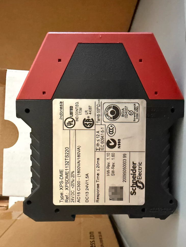

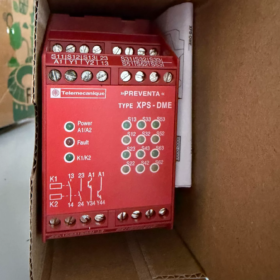
モデルの内訳 (XPS-DME-XPSDME1132TS220)
- XPS: Preventa series safety control modules
- DME: Specialized for coded magnetic safety door switches; までサポートします 6 磁気スイッチ, while DMB only supports 2 スイッチ
- 1132: Basic specifications
11: 24VDC電源
32: 2 safety normally-open contacts + 2 transistor signal outputs
- TS220: AC220V manual reset terminals
(Standard XPSDME1132 only supports 24V reset; TS220 accepts AC220V reset signals)
- Core Applications
Matched with シュナイダー coded non-contact magnetic safety doors (XCS-DMC / XCS-DMP), used for guard door monitoring on machine tools, packaging equipment and automated production lines:
A single module can connect up to 6 coded magnetic switches in series, achieving the highest safety rating Cat.4 / PL e
Instantly cuts off the safety circuit upon door opening, wire breakage, short circuit or switch failure
Transistor outputs send fault diagnostics to PLC; front-panel LEDs indicate channel faults
- 安全認証の評価 (重要な情報)
| 標準 | 評価 |
| ISO 13849-1 | カテゴリ 4, PL e |
| IEC 61508 / IEC 62061 | シル 3 / SILCL3 |
| Machinery Safety Standards | で 1088, で 60204-1 |
| 認証 | CE, UL, テュフ |
- 電気仕様
4.1 電源
評価済み: 24 VDC (許容範囲: 17~30 VDC), power consumption ≤3.5W
4.2 Safety Inputs (Magnetic Switch Channels)
入力電流: 8mA pulse detection, anti-bypass short-circuit protection
Maximum cable resistance per circuit: 100おお
Maximum cable length per channel: 2000メートル
Max monitored devices: 6 coded magnetic switches in series (カテゴリー4); より多い 6 switches downgrades rating to Cat.3
4.3 出力接点
- Main Safety Contacts (2 forced-guided NO contacts)
Thermal current Ith=6A per channel, total combined current ≤12A
AC load: 230VAC 0.75A (AC15)
直流負荷: 24VDC 1.5A (DC13, L/R=50ms)
Output protection: 4A gG fuse / 6A fast-blow fuse
- PLC Signal Outputs (2 solid-state transistors)
最小荷重: 17V / 10ミリアンペア
Output opens during faults or door opening for upper-level diagnosis
4.4 リセット機能 (TS220 Exclusive)
Reset terminals support manual reset triggered by either 24VDC or AC220V
応答時間: ≤20ms
4.5 環境 & 機械的データ
動作温度: -10℃~+55℃
保管温度: -25℃~+85℃
保護クラス: Housing IP40, terminals IP20
取り付け: 35mm DINレール, dimensions 22.5×109×117mm
端子: ネジ端子, wire cross-section 0.14~2.5mm²
- Brief Terminal Definition
- 電源: A1(24V+) / A2(0V)
- 6 magnetic switch input channels: Grouped channels S11-S12 / S11-S13
- Reset circuit: Y1-Y2 (TS220 compatible with AC220V / DC24V reset pushbuttons)
- Safety outputs: 13-14, 23-24 (2 safety normally-open contacts)
- Diagnostic transistor outputs: 31-32, 41-42 (PLC status feedback)
- Obsolete Replacement Solution (公式アップグレード)
The XPS-DME series has been discontinued. Direct replacement model: XPSUDN13AP
代替品の説明
- Full functional compatibility: サポート 6 coded magnetic switches, Cat.4 PL e SIL3
- Universal reset: XPSUDN13AP accepts 24V AC/DC and 220VAC reset, fully covering TS220 requirements
- Terminal definitions match one-to-one; no cabinet wiring modification required
- Same 22.5mm DIN rail width; no cabinet space adjustment needed
- 典型的なアプリケーションシナリオ
- Safety guard doors for machining centers and injection molding machines
- Fencing of robot workcells and access doors for automated production lines
- Non-contact magnetic door interlocks for food packaging and lithium-ion battery equipment
- Multi-door machinery (3~6 guard doors controlled by one safety relay)
- Key Fault Troubleshooting Points
- Red channel LED illuminated: Corresponding magnetic switch open, wire breakage or short circuit
- No response to reset button: Mismatched reset circuit voltage (verify AC220/DC24 supply for TS220), contact welding
- Safety outputs fail to close: Input channel fault, incomplete reset, undervoltage supply
- No feedback signal to PLC: Solid-state output load below 10mA
Application Scenarios of Schneider XPSDME1132TS220 Safety Relay
Preconditions for Product Compatibility
This module is specially designed for Schneider coded magnetic safety door switches (XCS-DMC / XCS-DMP). まで 6 non-contact magnetic switches can be connected in series, with safety rating Cat.4 / PL e / SIL3. It supports dual-voltage manual reset (AC220V/DC24V) and is ideal for multi-guard-door machinery. Free from mechanical contact wear, dustproof and waterproof for harsh operating environments.
- Machine Tool Processing Industry
- 垂直 / Horizontal Machining Centers, CNC Milling Machines, 旋盤
Front and rear machine guard doors, tool magazine access doors, spindle safety shields monitored in series. Servo and spindle power cuts off immediately upon door opening. Non-contact magnetic switches resist coolant and metal chip accumulation without jamming failures seen in mechanical door locks.
- Grinders, Punch Presses, Press Brakes, Shears
Safety fencing and mold access doors for sheet metal stamping equipment, compliant with machinery safety standard EN1088 to prevent crushing injuries from accidental door opening. Multiple doors monitored collectively; opening any single door triggers full-machine emergency stop of the safety circuit.
- 放電加工 & Wire Cut Machines
Sealed guard doors for dielectric fluid enclosures. Magnetic switches eliminate contact oxidation in humid environments, suitable for damp and corrosive working conditions.
- 自動生産ライン & Robot Workcells
- 6-axis Robots, Collaborative Robot Fencing
3~6 segmented safety fence doors surrounding robot cells wired in series to this module. Robot servo drives cut off instantly if any door opens. Two transistor diagnostic outputs connect to PLC to pinpoint faulty doors for easy maintenance.
- 組立ライン, Robot Loading/Unloading Stations
Side equipment access doors and material retrieval guard doors for continuous-production lines. Magnetic switches offer far longer service life than mechanical safety door switches, reducing downtime for repairs.
- Automated Warehousing, Stackers, AGV Enclosures
Rack maintenance safety doors and equipment isolation guards. Supports maximum 2000m cable length for long-distance wiring, suitable for large warehouse plants.
- 包装, 印刷 & Rubber/Plastics Equipment
- Injection Molders, Blow Molders, 押出機
Mold access doors and high-temperature barrel safety shields for high-temperature, oily environments. Coded magnetic switches prevent bypass tampering and illegal short-circuiting of safety doors.
- Food Packaging Machines, Carton Formers, シーラー
Food production lines requiring washdown cleaning. Magnetic switches carry IP67 waterproof rating resistant to water rinsing. Centralized monitoring of multiple guard doors complies with food machinery safety regulations.
- Printing Presses, Laminators, スリッター
Guard doors covering roller transmission assemblies. High-speed equipment demands fast safety circuit cut-off; module response time ≤20ms.
- 新エネルギー & リチウム電池装置
- Li-ion Coating, 巻き上げ, Electrolyte Filling, Formation Equipment
Safety doors for sealed cell processing chambers. Non-contact switches eliminate electric spark risks to meet dust and explosion-proof requirements of lithium workshops. Multiple chamber doors wired in series, with safety rating PL e satisfying lithium equipment acceptance standards.
- PV Silicon Wafer Cutting, Module Lamination Equipment
High-dust production environments avoid mechanical lock jamming caused by dust ingress, ensuring safe maintenance access for operators.
- ロジスティクス & Heavy Conveying Equipment
- Automatic Sorting Lines, Heavy Belt Conveyor Cabinets
Side maintenance doors on large sorting machines; まで 6 doors share one safety relay to save cabinet installation space. Narrow 22.5mm DIN rail design fits densely packed control cabinets.
- Lifting Platforms, Hydraulic Presses, Die Casting Machines
Safety guard doors for hydraulic power equipment. Forced-guided safety contacts feature self-detection of contact welding to eliminate hazardous failure modes.
- General Custom Automation & 試験装置
- Material Testing Machines, Impact Test Benches, High-Voltage Test Chambers
Safety doors for sealed test enclosures in high-voltage / impact hazard zones with multi-door interlock protection. AC220V reset matches standard plant AC control circuits without extra power conversion modules.
- Training Equipment, Small Automated Training Benches
Multi-station training guard doors. Dual PLC diagnostic outputs facilitate upper-level safety status collection for teaching monitoring systems.
- 不適切なアプリケーションシナリオ (Model Selection Pitfalls)
- Single guard door applications (XPSDME01 series smaller model recommended for better cost performance)
- Dedicated circuits for emergency stop buttons, safety mats or light curtains (this model only supports coded magnetic door switches and cannot directly connect light curtains / E-stops)
- High-risk Zone 1 / ゾーン 2 explosive atmospheres (explosion-proof magnetic switches and enclosures required as matching accessories)
- より多い 6 guard doors wired in series (超える 6 switches downgrades safety rating to Cat.3, failing high-end equipment acceptance standards)
Summary of Core Advantages for Applications
- Centralized monitoring for multi-door machinery (2~6 guard doors) to reduce quantity of safety relays
- Non-contact magnetic switches compatible with harsh environments containing oil, ほこり, moisture and washdown cleaning
- AC220V reset suitable for legacy equipment retrofits without replacing existing 220V reset pushbuttons
- Highest Cat.4 safety rating, meets TÜV/UL certification acceptance for equipment exported to EU and North America
Standard Complete Installation & Commissioning Procedures for Schneider XPSDME1132TS220 Safety Relay
- インストール前の準備 (安全規則: All Operations Performed With Power Disconnected)
1.1 ツール & 材料
フィリップス & flat screwdrivers, マルチメータ, electrical insulation tape, ケーブルタイ, shielded twisted pair cable (dedicated for magnetic switches)
Compatible coded magnetic door switches: XCS-DMC / XCS-DMP (ordinary mechanical locks or light curtains cannot be connected)
Reset pushbutton: Universal self-reset pushbutton for AC220V/DC24V (terminals Y1-Y2 support dual voltages)
Cable specifications: Control wires 0.5~1.5mm²; safety output power wires 1.0~2.5mm²
1.2 環境 & Installation Condition Inspection
- Control cabinet operating temperature: -10℃~+55℃, keep away from strong electromagnetic interference sources such as inverters and contactors
- Module width 22.5mm for standard 35mm DIN rail; reserve ≥15mm clearance above and below for heat dissipation
- Take protective measures against dust, cutting fluid and moisture inside cabinets. Module IP40 rating restricts use inside cabinets only; outdoor direct mounting prohibited
- Confirm power supply: Module A1/A2 fixed 24VDC (17~30VDC); reset circuit supplied independently by either AC220V or DC24V
1.3 Visual Pre-Installation Inspection
Intact housing, no burnt terminals, functional indicator LEDs
モデルの検証: XPSDME1132TS220 (TS220 = AC220V reset variant; do not interchange with standard XPSDME1132)
Confirm maximum 6 coded magnetic switches in series; より多い 6 devices downgrades safety rating to Cat.3
- ハードウェアのインストール手順
ステップ 1: Mount Module onto DIN Rail
- Cut off total cabinet power supply; confirm full disconnection of 24VDC and 220VAC power
- Hook bottom latches of module onto 35mm rail, press module down until top latch self-locks
- Shake lightly left and right to confirm firm mounting. No gaps required when multiple modules installed side-by-side; maintain unobstructed heat dissipation channels
ステップ 2. System Wiring Standards (Mandatory EMC Requirements)
- Separation of Strong & Weak Current Circuits
Route 24V control signal cables (磁気スイッチ, PLC diagnostics) separately from AC220V reset and main power cables in distinct trunking with ≥10cm spacing; long parallel runs inside the same conduit forbidden
Use twisted shielded cable for magnetic switches; single-end grounding of shield layer inside control cabinet
- Unused Channel Handling (致命的)
This module contains 3 groups of dual-channel inputs S1, S2, S3, each with terminals Sx1-Sx2, Sx1-Sx3:
Wire channels corresponding to installed doors; short-circuit Sx1 and Sx3 for all unused channels. Otherwise channel faults will trigger upon power-up and reset will be disabled
例: のみ 2 doors used – short S31-S33 with jumper wire; all 3 channel groups wired for 6 ドア
- Terminal tightening torque 0.6~0.8N·m; no loose copper strands or cross-terminal short circuits on conductors
ステップ 3. Full Terminal Wiring Definition
- Main Power Circuit (Fixed 24VDC)
A1: 24V DC Positive; A2: 0V DC Negative
- Magnetic Switch Input Channels (Dual-channel redundancy, core for Cat.4)
S11/S12/S13: 1st group magnetic switches; S21/S22/S23: 2nd group; S31/S32/S33: 3rd group
Two contacts of each coded magnetic switch are wired in series to corresponding Sx2 and Sx3; all Sx1 common terminals connected in parallel
- Reset Circuit Y1-Y2 (TS220 Exclusive Dual-Voltage)
AC220V reset: Y1 connected to Live L, Y2 connected to Neutral N, in series with self-reset pushbutton
DC24V reset: Y1 connected to 24V+, Y2 connected to 0V, in series with self-reset pushbutton
Select only one voltage type; simultaneous connection of 220V and 24V prohibited
- Forced-Guided Safety Outputs (Cut off servo / main contactor circuits, wired in series)
13-14, 23-24: 2 安全接点はありません, max load 6A per channel, AC230V 0.75A (AC15)
The two contacts must be wired in series for safety circuit to satisfy Cat.4 redundant safety requirements
- PLC Solid-State Diagnostic Outputs (Passive transistor feedback)
31-32, 41-42: Open-circuited during door faults / door opening; conductive after all doors closed and reset executed, connected to PLC digital inputs
ステップ 4. Power-Down Post-Wiring Inspection (Mandatory Before Power-Up)
- Multimeter continuity test: All closed magnetic switch channels Sx2-Sx3 conductive; short-circuited unused channels Sx1-Sx3 conductive
- Reset pushbutton normally open, closed when pressed; no cable short circuits to ground
- No short circuits to ground or power supply at safety output terminals 13/14, 23/24
- No reverse polarity or short circuit on 24V supply A1/A2
- Step-by-Step Power-On Commissioning Process
段階 1: Power-On Self-Test (No-Load Bare Module Test)
- Energize module 24VDC supply first, then apply AC220V power to reset circuit
- 2-second module self-test: All LEDs illuminate simultaneously; internal circuits automatically detect short circuits, wire breaks and channel abnormalities
- Status differentiation after self-test completion:
Solid green RUN LED: 通常の電源; all red channel LEDs off: All doors closed, no wiring faults
Flashing red LED on any channel: Corresponding channel wire break, 短絡, unactuated magnetic switch or unshorted unused channel
段階 2: Basic Reset Function Commissioning
- Fully close all guard doors and confirm all red channel LEDs extinguish
- Press reset pushbutton for ≥0.5 seconds then release
- Normal performance: Green OUT output LED illuminates, 端子 13-14/23-24 行為, トランジスタ出力 31-32/41-42 turn on, PLC receives ready signal
- 異常: No response when reset button pressed
トラブルシューティング 1: One door incompletely closed / misaligned magnetic switch
トラブルシューティング 2: Unshorted unused input channel
トラブルシューティング 3: Mismatched reset circuit voltage, damaged normally-open pushbutton contact
トラブルシューティング 4: Reversed or broken wiring on Y1/Y2 terminals
段階 3: Safety Function Simulation Test (Mandatory Item for Equipment Acceptance)
テスト 1: Machine Stop Triggered by Single Door Opening
- Module outputs closed normally, equipment ready for operation
- Open any guard door
Standard response: Green OUT LED extinguishes within ≤20ms, both safety contacts open simultaneously, PLC diagnostic outputs de-energize
After re-closing door, reset button must be pressed again to restore outputs (manual reset mode; no automatic reset for this model)
テスト 2: Wire Break Fault Simulation (Cat.4 Self-Diagnosis)
- Disconnect power supply, remove wire from any Sx2 terminal to simulate wire breakage
- Re-energize power; corresponding red fault LED stays solidly illuminated
- Reset operation ineffective even with all doors closed; module latches fault state and cuts safety outputs
- After restoring wiring, power cycle module then close all doors and reset to clear fault
テスト 3: Multi-Door Interlock Test (2~6 Doors)
- Partial door closure with one door open: Reset disabled, fault LED alarm triggered
- Reset after all doors fully closed to energize outputs; immediate machine stop upon opening any single door
- Verify dual PLC diagnostic outputs distinguish global fault signals
テスト 4: Reset Voltage Compatibility Test (TS220 Feature)
For AC220V reset: Disconnect 24V reset supply, only energize 220VAC; reset function operates normally
For DC24V retrofit reset: Disconnect 220VAC supply, only energize 24VDC; reset function operates normally
Simultaneous AC220V and DC24V supply to Y1-Y2 forbidden, will burn reset circuit
段階 4: Full Machine On-Load Coordination Commissioning
- Wire safety contacts 13-14 そして 23-24 in series to main contactor / servo enable circuit
- Equipment start-up permitted after successful reset
- Door opening during running state: Main contactor opens instantly, power cut off without hazardous motion
- Fault upload verification: PLC collects signals from 31-32/41-42; touchscreen displays guard door fault alarms
- Acceptance Criteria Upon Completion of Commissioning
- No faults detected during power-on self-test; outputs activate normally after door closure and reset
- Safety circuit cut off instantly within <20ms upon opening any door
- Reliable fault latching triggered by wire breaks or short circuits; equipment cannot be illegally started
- Normal switching test of AC220V/DC24V reset circuits
- Synchronous make/break of dual safety contacts, eliminating single-point failure risk (Cat.4/PL e)
- Accurate PLC diagnostic signal feedback for remote fault identification
- インストール & Commissioning Prohibitions + Quick Fault Lookup
Strictly Forbidden Operations (Hard Safety Rules)
- Do not connect standard mechanical safety doors, light curtains or emergency stops to Sx input channels (only XCS-DMC/DMP coded magnetic switches compatible)
- Do not power up module with unused channels left unshorted – module permanently latches fault
- Do not wire only one of the two safety contacts; safety rating invalidated, equipment acceptance failed
- Do not supply both AC220V and DC24V to Y1-Y2 terminals simultaneously
- Do not route power cables and signal cables in long parallel runs inside same trunking; electromagnetic interference causes unintended machine stops
Quick Resolution for Common Commissioning Faults
- Solid red channel LED illuminated
Door incompletely closed, excessive mounting gap on magnetic switch; wire breakage/short circuit; unused channel not shorted
- No response to reset pushbutton
No power to reset circuit, damaged pushbutton; uncleared channel fault; incomplete closure of all doors
- Flickering OUT LED, frequent tripping
Excessive cable resistance from overlong wiring (>100Ω per circuit); poor shield grounding causing EMI; failed coding pairing of magnetic switch
- No diagnostic signal sent to PLC
Transistor output load current below 10mA; match PLC input current rating
- 定期的なメンテナンス & コミッショニングの重要なポイント
- 日常点検: Status of RUN, OUT and fault LEDs
- Quarterly re-test of wire break and door-stop safety functions
- Full re-run of fault simulation tests mandatory after replacing any magnetic switch
- For retrofits on legacy equipment, prioritize replacement model XPSUDN13AP for new projects with identical installation and commissioning logic





NH42-63-318x560.png "CHINT PC型自動切替スイッチ (ATS)NH42-63/4SZ")



