 コンタクタ,サーキットブレーカー,センサー,エンコーダ,PLC,コンバータ

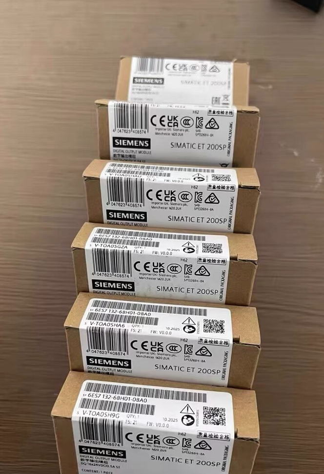

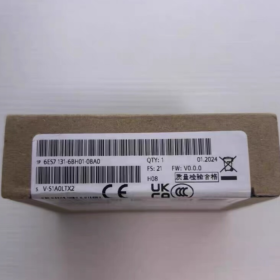
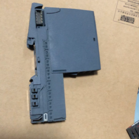
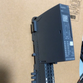
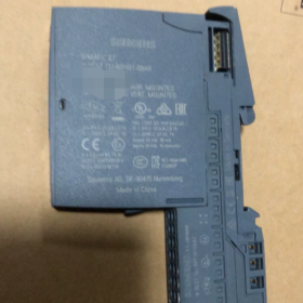
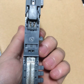
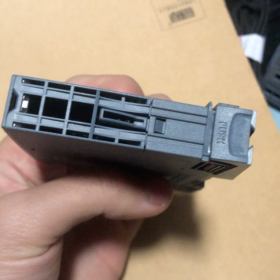
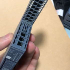
- フルモデルの指定 & 位置決め
SIMATIC ET200SP DI 16×24VDC ST Standard Digital Input Module of siemens
シリーズ: ET200SP Distributed I/O (PROFINET/PROFIBUS Remote Station)
関数: 16-チャネル 24 V DC digital input for collecting signals from PNP sensors such as switches, 近接スイッチ, photoelectric sensors and limit switches
Coding Type: Mechanical Coding Type A, only compatible with Type A0 BaseUnit
モデルコードの内訳
| コードセグメント | 意味 |
| 6ES7131 | ET200SP Digital Input (から) Module Series |
| 6BH01 | 16-チャネル 24 V DC Standard DI, Hardware Version V1 |
| 0BA0 | Standard industrial version, no anti-corrosion coating and no surge suppression enhancement |
- コアの電気仕様
2.1 電源 & 入力特性
定格電源: 24 ワシントンDCで, permissible range 19.2 ~ 28.8 V, with reverse polarity protection
入力タイプ: P-reading (Sinking PNP Input, IEC 61131 タイプ 3)
論理 0: -30 V〜 +5 V
論理 1: +11 V〜 +30 V
Typical On-state Current per Channel: 2.5 ミリアンペア; 最大合計モジュール電流: 90 ミリアンペア
標準的な消費電力: 1.7 W
チャネルのグループ化: Two groups (Channels 0~7 / 8~15). All sensors within one group must be uniformly PNP or NPN; mixed wiring is prohibited.
2.2 Filter Delay (8 configurable levels in TIA Portal)
0.05 / 0.1 / 0.4 / 0.8 / 1.6 / 3.2 / 12.8 / 20 MS
Additional cable delay of 30 ~ 500 μs. A filter setting ≥3.2 ms is recommended for environments with heavy interference from inverters.
2.3 Maximum Cable Length
シールドケーブル: 1000 m maximum
Unshielded Cable: 600 m maximum
- 機械構造 & インストール
- 寸法: 15 mm (W) × 73 mm (H) × 58 mm (D), ultra-narrow compact design
- 保護クラス: IP20, DIN rail mounting inside control cabinet only
- 周囲温度
水平取り付け: 0 ~ +60 ℃
垂直取り付け: 0 ~ +40 ℃
ストレージ & 交通機関: -25 ~ +70 ℃
- 指標: Independent green LED for each channel (ON = Logic 1, OFF = Logic 0); no dedicated hardware fault LED
- Address Occupancy: Consumes 2 input bytes plus an additional 2 bytes for diagnostic QI information. Hardware interrupt, isochronous mode and counter functions are not supported.
- Wiring Diagrams (Type A0 BaseUnit Mandatory)
4.1 2-wire Passive Contacts (Limit Switches, Pushbuttons)
Wire directly to the A0 BaseUnit: one contact terminal connects to DIx, the other to M (24 Vマイナス). For wire breakage detection, connect a 25 ~ 45 kΩ resistor in parallel with the contact.
4.2 3-wire PNP Sensors (Common Photoelectric / Proximity Switches)
Potential distribution terminal required:
Sensor Brown Wire: L+ 24 V
Sensor Blue Wire: Common M Ground
Sensor Black Wire (信号): Connect to module DI channel
> NPN sensors must not be directly wired to this module; 論理 1 signals cannot be detected.
4.3 2-wire Inductive Proximity Sensors
Maximum closed-circuit current limited to 1.5 ミリアンペア. Long cables may trigger false wire-breakage alarms.
- 診断機能 & 機能上の制限
- Supports wire breakage diagnosis (parallel detection resistor required); short-circuit diagnosis unavailable
- No channel-level overcurrent protection; sensor short-circuits will not trigger individual channel fault alarms
- No encoder power supply output and no auxiliary 24 V DC電源
- Supports I&M0 ~ I&M3 device information; hardware automatically recognized by TIA Portal
- 通信互換性: S7-1200/1500 CPU, ET200SP CPU, プロフィネットIO, プロフィバスDP
- Comparison of Derivatives in the Same Series
| Model Number | 違い | 代表的な用途 |
| 6ES7131-6BH01-0BA0 | Standard basic DI without anti-corrosion coating | General workshops, standard equipment under normal temperature |
| 6AG1131-6BH01-7BA0 | SIPLUS anti-corrosion coating, 動作範囲 -40 ~ +70 ℃ | Chemical plants, ポート, high-humidity corrosive environments |
| 6ES7131-6BH01-0CA0 | サージ抑制機能を内蔵 | Long-distance field cables, lightning-prone areas |
| 6ES7131-6BH00-0BA0 | Obsolete older model, fully hardware compatible | Spare part replacement for legacy equipment |
- 典型的なアプリケーションシナリオ
- 自動車組立ライン: Signal collection for fixture position confirmation, safety gates and workstation pushbuttons
- 包装 & 物流機器: Photoelectric counting, jam detection switches, sorting trigger signals
- Water Treatment Systems: Float level switches, valve limit switches, pump running feedback signals
- 工作機械の自動化: Travel limit switches, tool detection, safety circuit contacts
- モデルの選択 & 操作上の注意事項
- Only Type A0 BaseUnit is permitted; Type B0/C0 and other coded base units are incompatible. The module features an integrated Type A coding lock to prevent incorrect insertion.
- All sensors within each 8-channel group must share the same polarity; PNP and NPN devices cannot be mixed in one group.
- Cables routed near inverters and servo drives must be shielded to eliminate false triggering.
- Increase input filter delay for long cables to suppress electromagnetic interference.
- No SIL safety certification. This module cannot be used independently for safety circuits; safety relays or safety I/O modules are required.
- Alternative Replacement Options
- Direct equivalent replacement: 6AG1131-6BH01-7BA0 (wide-temperature anti-corrosion version)
- Higher-density upgrade: 6ES7131-6BF01-0BA0 (8-channel isolated DI module)
- Safety application replacement: 6ES7131-6FD01-0BB1 (安全DI, シル 2 準拠した)
Full Operating Principle of Channel Grouping for 6ES7131-6BH01-0BA0
- Hardware Group Definition (修理済み 8 Channels per Group, 2 Groups Total)
の 16 input channels are physically divided into two independent reference potential domains with completely separated internal hardware circuits:
- グループ 1: Channels DI.0 ~ DI.7 (初め 8 ポイント)
- グループ 2: Channels DI.8 ~ DI.15 (Last 8 ポイント)
Core Underlying Logic: Independent Common Reference M per Group
The module assigns a separate M reference ground to each group internally, with no electrical connection between the two groups.
All channels within one group share the same group M potential. 全て 8 channels in a single group must use identical sensor polarity (all PNP or all NPN); the two groups may adopt different polarities.
- Circuit Operation of Channel Groups
2.1 Standard Mode (工場出荷時のデフォルト: PNP / Sinking P-reading)
Internal circuit structure for each group:
Each DIx channel is internally pulled up to 24 ワシントンDCで
Signal conduction condition: DIx connected to 0 V (M) → Circuit closed, PLC detects Logic 1
Compatible with 3-wire PNP sensors and 2-wire passive contacts (押しボタン / リミットスイッチ)
配線ルール:
Negative terminals of all sensors in the group connect uniformly to the group M terminal
PNP and NPN sensors cannot coexist in one group; otherwise partial channels remain permanently Logic 0 or Logic 1.
2.2 Wiring NPN Sensors to a Single Group (Source Output)
NPN sensors output low-level 0 V signals which cannot be recognized by default. Modify the group common M connection to 24 V L+:
DIx receives high-level 24 V signal from NPN sensor to close the circuit
Only the target group’s common potential needs adjustment; the other group remains unaffected.
2.3 Key Isolation Features of Group Separation
No electrical linkage between the two groups. It is fully allowed to connect Group 1 M to 0 V and Group 2 M to 24 V L+.
Short-circuit or ground faults on one group will not interfere with signal acquisition on the other group.
Sensors on long cables or separate power supply loops can be grounded in separate groups to reduce ground loop interference.
- Mapping Between I/O Addresses and Channel Groups (PLC Memory Area)
の 16 channels occupy 2 input bytes, strictly allocated by group in one-to-one correspondence:
グループ 1 (から.0~DI.7): `IBx` (1st byte, bit0 ~ bit7)
グループ 2 (DI.8~DI.15): `IBx+1` (2nd byte, bit0 ~ bit7)
例: Module start address IB100
DI0~DI7 = I100.0 ~ I100.7
DI8~DI15 = I101.0 ~ I101.7
Diagnostic QI status data is uploaded in two segments corresponding to each group.
- Terminal Layout of Type A0 BaseUnit Matching Channel Groups
Terminal arrangement logic of matching A0 BaseUnit:
- Terminals 1~8: から.0~DI.7 (グループ 1) + グループ 1 Common M
- Terminals 9~16: DI.8~DI.15 (グループ 2) + グループ 2 Common M
The base unit is equipped with two independent M terminals physically separated for connecting different potentials to each group.
- Three Typical Practical Wiring Scenarios for Grouping
シナリオ 1: All PNP Wiring (最も一般的な)
グループ 1 M and Group 2 M shorted together to 0 V (24 Vマイナス)
Uniform 3-wire PNP sensors and passive switches for both groups with no conflict
シナリオ 2: One Group PNP, One Group NPN (Permitted)
グループ 1 (DI0~7) M connected to 0 V → Wired with PNP photoelectric / proximity sensors
グループ 2 (DI8~15) M connected to 24 V L+ → Wired with NPN sensors
This configuration is valid. Independent group potentials do not interfere with each other, and all signals are recognized normally.
シナリオ 3: Mixed PNP & NPN Within One Group (Strictly Forbidden)
例: DI0~4 wired to PNP sensors, DI5~7 wired to NPN sensors
The group only has one shared M potential, creating circuit conflicts with the following phenomena:
Partial channels permanently no signal (constant Logic 0)
Random false triggering and signal flickering
Severe cases cause input circuit overload and permanent module channel damage
- Group-Based Diagnostic Functions
Wire breakage detection operates on a per-group basis:
Detection resistors are wired in parallel to all channels in one group; wire-break diagnosis is enabled/disabled for the entire group at once
A wire break fault detected in one group only triggers diagnostics for that group, leaving the other group unaffected
Filter delay parameters apply to the entire module; independent filter settings per group are unsupported.
- Engineering Advantages of Dual-Group Design
- Dual-sensor compatibility: Direct wiring for PNP and NPN sensors without intermediate relays
- Isolation of different potential loops: Separate high-power and low-power machine tool signals into two groups to mitigate common-mode interference
- Fault zoning: Short-circuit or ground faults on one group will not disable all 16 チャンネル
- Flexible cabling: Each group can be powered by an independent 24 V DC電源; power faults on one supply do not impact the other group.
- Quick Summary
- Hardware fixed into 2 groups of 8 それぞれのチャンネル, with an independent common reference M for every group
- All sensors within one group must share identical polarity; the two groups may use different polarities freely
- Address allocation, diagnostic data and common reference potentials are managed separately by group
- Core essence: The two groups feature electrically isolated input circuits and share only the module power supply.





NH42-63-318x560.png "CHINT PC型自動切替スイッチ (ATS)NH42-63/4SZ")



