 접촉기,회로 차단기,태양광 인버터,전기 계량기,태양 전지


Step-by-Step Model Code Decoding
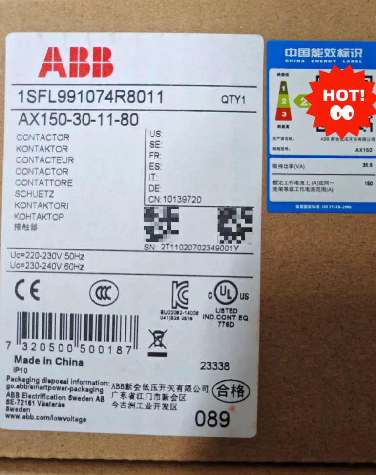
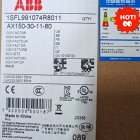
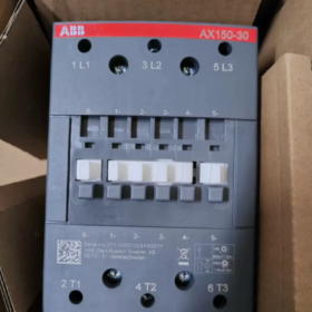
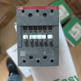
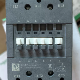
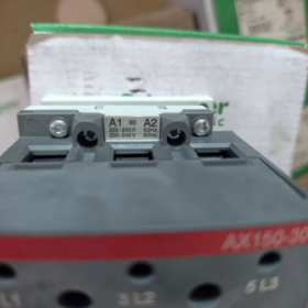
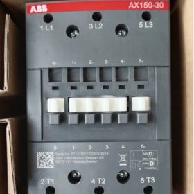
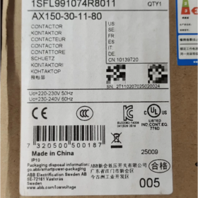
AX150-30-11-80
- 도끼: New generation general-purpose AC 접촉기 series of 씨줄
- 150: Rated operational current of 150A under AC-3 load at 400V
- 30: 3-극 주요 접점, 3 평상시 열려 있음 (no main normally closed contacts)
- 11: Built-in standard auxiliary contacts: 1 평상시 열림 + 1 평상시 닫힘 (1아니요+1NC)
- 80: Coil code → AC 220–230V 50Hz / AC 230–240V 60Hz (Standard domestic AC 220V coil)
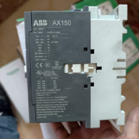
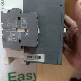
Original factory material order number: 1SFL991074R8011
Domestic catalog order number: 10139720
- 핵심 전기 매개변수
2.1 Main Circuit Load (IEC 60947-4-1)
| 매개변수 항목 | 사양 값 |
| Rated motor current under AC-3 (400다섯 / 55℃) | 150에이 |
| Controlled motor power at 400V | 75kW |
| AC-1 resistive thermal current (40℃ / 690다섯) | 190에이 |
| AC-1 resistive thermal current (55℃ / 690다섯) | 145에이 |
| Rated insulation voltage Ui of main circuit | 690다섯 |
| Maximum allowable operating voltage of main circuit | 1000뷔와 |
| 정격 전류 내전압 Uimp | 8kV |
| Making and breaking capacity under AC-3 | 10×즉 (1500에이) |
| Maximum operating frequency | 300 작업/시간 |
2.2 Coil Control Circuit
코일 전압: 220–230V 50Hz; 230–240V 60Hz
| Pull-in voltage range: 0.85~1.1 × rated voltage
드롭아웃 전압: ≤0.1 × rated voltage
코일 종류: AC excitation coil
2.3 보조 연락처
표준 구성: 1아니요 + 1NC, no extra auxiliary contact blocks required
Rated current of auxiliary contacts: 6A AC-15
- 환경 & 기계적 매개변수
- 주변 온도
Without thermal overload relay: -40℃ ~ +70℃
Matched with thermal overload relay: -25℃ ~ +55℃
보관온도: -40℃ ~ +70℃
- 설치 고도: ≤3000m (Derating is required above 3000m)
- 전체 치수: W 90mm × H 148mm × D 123.5mm
- 장착 방법: Dual-purpose for standard 35mm DIN rail mounting and screw fixing
- 터미널 연결: Main circuit busbar connection, compatible with cable/busbar crimping
- 보호 등급: IP20 (For indoor cabinet installation only)
- 일반적인 애플리케이션 시나리오
- 3상 비동기 모터의 스타트-스톱 제어 (75kW motors for fans, 물 펌프, 공기 압축기, 사출 성형 기계)
- Switching contactors for capacitor compensation cabinets (AC-1 load)
- High-power load control for central air conditioning and HVAC systems
- Power circuits for machine tools, lifting and conveying equipment
- Standard power switching device for power distribution cabinets and complete control cubicles
- Optional Matching Accessories
TA200DU series thermal overload relays (Matching 150A current range)
Mechanical interlock module (For forward/reverse bidirectional control)
측면 장착 / front-mounted extended auxiliary contact modules
Surge suppressors (RC흡수체, varistor for coil protection)
Terminal protective covers
- Equivalent Replacement Reference
- 같은 시리즈, same current rating with different coil voltages:
AX150-30-11-81: AC 110V coil; AX150-30-11-84: AC 380V coil
- Upgrade replacement for old model: A150-30-11 → AX150-30-11 (Direct interchange, identical mounting dimensions)
- Cross-brand equivalent alternatives: Schneider LC1D150, Siemens 3RT1056
- 주요 장점
- IEC를 준수, CE and national standards; 유형 2 short-circuit coordination, safe and reliable when matched with circuit breakers/fuses
- Mirror contact design, applicable to safety circuits and interlock control
- Eco-friendly flame-retardant materials, 저전력 코일, low temperature rise during long-term operation
- 컴팩트한 사이즈, less cabinet space occupation compared with the old A series
Official Mechanical Endurance Parameters of ABB AX150-30-11-80
- Mechanical Durability
10 백만 개의 작업 (10×10⁶ cycles)
테스트 조건: No load on the main circuit; only reciprocating make/break driven by the coil mechanism. No electric arc or contact electrical wear; only mechanical service life of springs, armature, brackets and other mechanical components is assessed.
- Key Supporting Frequency Parameters
Maximum mechanical operating frequency: 3600 작업/시간 (Standard no-load test condition)
Maximum electrical operating frequency (AC-3 모터 부하): 300 작업/시간 (Load start-stop, limited by contact arcing)
- Distinction: Mechanical Life vs Electrical Life (AC-3 Working Condition)
| 목 | 값 | 설명 |
| 기계적 수명 | 10 백만 사이클 | No current, only mechanical abrasion |
| AC-3 전기적 수명 | 대략. 1 백만 사이클 | For start-stop control of 75kW motors; contact arc erosion determines replacement cycle |
- 보충 노트
- All high-current models of the full AX series (AX110/AX150/AX185/AX205) share a uniform mechanical life of 10 백만 사이클; the old A150 also features 10 million mechanical cycles with structurally compatible direct replacement.
- 주변 온도, 고도, dust and oil contamination will slightly shorten the actual mechanical service life; the nominal value can be achieved under clean cabinet and normal temperature conditions.
- The mechanical life remains unchanged at 10 million cycles after installing a mechanical interlock module in reversible control circuits.
Complete Operating Principle of ABB AX150-30-11-80 AC Contactor
- Core Internal Structure
- Electromagnetic Driving System (코일 + Fixed Core + Movable Armature)
코일: The coil with code 80 is an AC 220V excitation coil wound on the fixed core.
Fixed Core: Fixed base fitted with a shading ring on the end face (Core noise and vibration suppression component for AC contactors)
Movable Armature: Movable iron core linked synchronously with main and auxiliary contacts
Return Spring: Pushes the armature open under normal state to ensure reliable contact separation after power-off
- Main Contact Circuit (3 Normally Open Main Poles)
Three sets of high-power silver alloy moving and fixed contacts that carry 150A three-phase main circuit current to control loads such as 75kW motors.
- 보조 연락처 (1아니요+1NC)
Operate synchronously with main contacts, used for self-locking, interlocking, signal feedback and indicator light circuits, rated at 6A.
- 아크 슈트
Grid-type metal arc shield that splits and cools electric arcs during heavy current breaking to prevent contact melting and welding.
- 베이스 & Linkage Bracket
Insulated plastic bracket that drives all moving and fixed contacts to open/close synchronously with armature movement.
- Make Operation When Energized
- Rated AC 220V voltage is supplied to the coil via the control circuit, generating an alternating magnetic field.
- Electromagnetic attraction produced by the fixed core overcomes the tension of the return spring and pulls in the movable armature.
- The linkage bracket moves downward synchronously:
Three sets of main normally open contacts close, conducting the three-phase main circuit and energizing the motor/load for operation.
Auxiliary Normally Open (아니요) contacts close and auxiliary Normally Closed (NC) contacts open.
- Function of the shading ring on the fixed core end face: AC voltage crosses zero every cycle, causing instantaneous magnetic field disappearance and attraction drop. The shading ring induces a lagging current to maintain partial attraction, eliminating high-frequency armature chattering, abnormal noise and contact sparking.
- No electric arc occurs inside the arc chute, and the circuit conducts stably.
- Break Operation When De-energized
- Coil power supply from the control circuit is cut off; the alternating magnetic field of the coil vanishes rapidly and electromagnetic attraction drops to zero.
- The return spring rebounds instantly to separate the movable armature from the fixed core.
- All contacts reset synchronously:
Three groups of main contacts open, 주회로를 차단하고 부하를 정지한다..
Auxiliary NO contacts open and NC contacts restore closed state.
- High-voltage electric arcs generate the instant main contacts separate (Current cannot mutate for inductive loads).
The arcs enter the arc chute, split into small segments by multi-layer metal grids, cool down rapidly and extinguish to avoid contact fusion welding.
- Self-Locking Control Principle (Standard Motor Start-Stop Circuit)
- Press the start button → Coil energizes, contactor pulls in and auxiliary NO contact closes synchronously.
- After releasing the start button, current continuously feeds the coil through the closed auxiliary NO contact to sustain the pull-in state (Self-locking function).
- Press the stop button to cut off coil power; the spring releases the armature, all contacts of the contactor reset and the equipment shuts down.
- Key Matching Protection Logic
- Matching with thermal overload relay: Under overload conditions, the normally closed contact of the thermal relay opens the contactor coil circuit and cuts off motor power supply.
- Mechanical interlock installed for reversible circuits: Interlock two AX150 contactors to prevent simultaneous pull-in of forward and reverse contactors which would cause three-phase short circuit.
- RC surge suppressor connected in parallel with the coil: Absorbs induced high voltage generated during breaking to avoid breakdown of low-current contacts of PLCs and relays.
- Core Difference Between AC and DC Contactors (AX Series Equipped with AC Coils)
The AX150 adopts AC excitation and relies on a shading ring to eliminate vibration. DC contactors require no shading ring and maintain pull-in via constant magnetic attraction.
AC electric arcs extinguish more easily than DC arcs upon power cut-off; paired with grid arc chutes, it meets the requirement of breaking 150A heavy current.


, 코일 전압 110V AC, 그리고 장착되어 있습니다 1 평상시 열림 (1아니요) 보조 접점")
. 권장 교체품: LC1D115KUEC 또는 LC1E120M5N")

 Schneider LC1D38BLDC24V는 TeSys D 시리즈의 저소비 전력 DC 코일 접촉기입니다.. 정격 전류 38A 제공, 24V 저전력 DC 코일, 3NO+1NO+1NC 접점 구성 및 45mm 폭의 컴팩트한 디자인, 산업 자동화를 위한 이상적인 선택입니다. 에너지 효율성의 장점,")

")
NH42-63-318x560.png "CHINT PC형 자동절환스위치 (ATS)NH42-63/4SZ")


